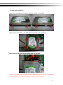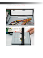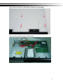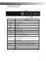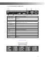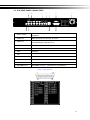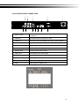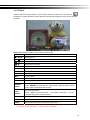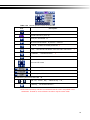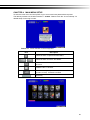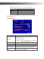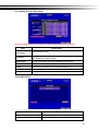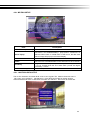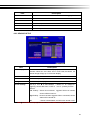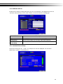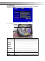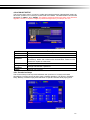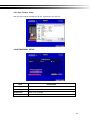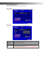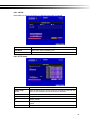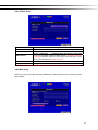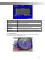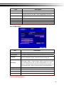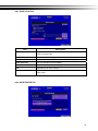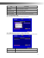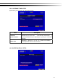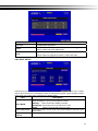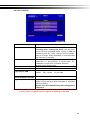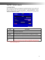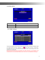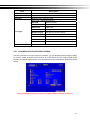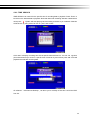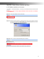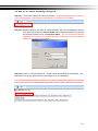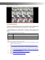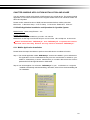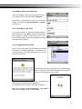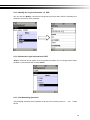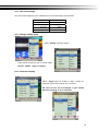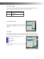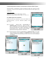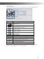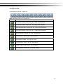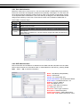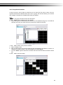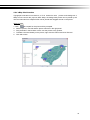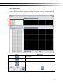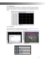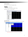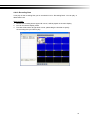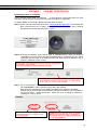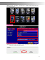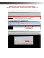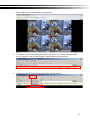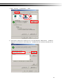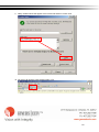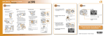
1
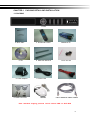
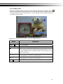
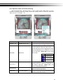
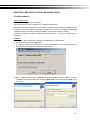
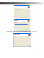
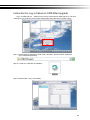
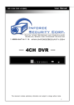
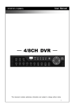
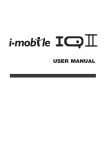
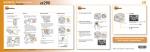
DVR - HSD8000 / HSD6000 Series User Manual ─ DVR - HSD6000 / HSD8000 Series ─ User Manual This do cument cont ains p reliminary inform ation and subje ct to chang e witho ut notice. WARNING TO REDUCE THE RISK OF FIRE OR ELECTRIC SHOCK, DO NOT EXPOSE THIS APPLIANCE TO RAIN OR MOISTURE. This symbol is intended to alert the user to the presence of unprotected “Dangerous voltage" within the product's enclosure that may be strong enough to cause a risk of electric shock. This symbol is intended to alert the user to the presence of important operating and maintenance (servicing) instructions in the literature accompanying the appliance. NOTE: This equipm ent has b een te sted and fou nd to com ply with the limit s fo r a class digit al device, pu rsuant to p art 15 of the FCC Rul es. The se limit s are de signed to provide reasona ble p rotection ag ainst harmful interference when the equipment is operated in a commercial enviro nment. This equipment gen erates, u ses, and can radiate ra dio frequ ency e nergy and, if not installed and used in accorda nce with the instruction manual, ma y cause h armful interference to radi o comm unications. Operation of this equipment in a resi dential area is likely to cause harmful interference in whi ch ca se the use r wi ll be requi red to correct the interference at his own expense. Disposal of Old Electrical & Electronic Equipment (Applicable in the European Union and other European countries with separate collection systems) This symbol on the pro duct or on its p ackaging indicates that this pro duct shall not be treated as household waste. Inste ad it shall be handed ov er to the applicable collectio n point for the recycling of electrical an d ele ctronic equipment. By ensuring this product is disposed of correctly, you will help prevent pot ential neg ative consequences fo r the environment and human he alth, which co uld otherwi se be cau sed by inapprop riate waste ha ndling of this product. The recycling of material s will help to conserve natural resources. For more detail ed information about recycling of this product, please contact your local city office, your household waste disposal service or the shop where you purchased the product. 2 Table of Contents CHAPTER 1 P ACKING DET AIL AND INST ALLATION _____________________ 5 1-1 PACKING ___________________________________________________ 5 1-2 Hard Disk Installation ________________________________________ 6 1-3 DVD-RW Installation(Only Support DVD/RW) ____________________ 7 CHAPTER 2 P ANEL L OCATION ________________________________________ 9 2-1 FRONT PANEL CONTROLS ___________________________________ 9 2-2 16CH REAR PANEL CONNECTORS___________________________ 10 2-3 8CH REAR PANEL CONNECTORS ____________________________ 11 2-4 4CH REAR PANEL CONNECTORS ____________________________ 12 CHAPTER 3 LIVE, PLA YBACK AND PTZ OPERATIONS _________________ 13 3-1 LIVE Mode_________________________________________________ 13 3-2 PLAYBACK Mode___________________________________________ 16 3-3 PTZ Mode _________________________________________________ 18 CHAPTER 4 MAIN MENU SET UP ____________________________________ 20 4-1 RECORD SETUP ___________________________________________ 21 4-1.1 Quality & Frame Rate Setup ____________________________ 22 4-2 EVENT SETUP _____________________________________________ 22 4-2.1 MOTION SETUP _______________________________________ 23 4-2.1.1 MOTION AREA SETUP_____________________________ 23 4-2.2 SENSOR SETUP _______________________________________ 24 4-3 SCHEDULE SETUP _________________________________________ 25 4-3.1 Schedule Record Setup ________________________________ 25 4-3.2 Holiday Setup _________________________________________ 26 4-4 CAMERA SETUP ___________________________________________ 26 4-5 ACCOUNT SETUP __________________________________________ 27 4-5.1 Permission Setup ______________________________________ 27 4-5.2 User Picture Setup ____________________________________ 28 4-6 NETWORKING SETUP _______________________________________ 28 4-6.1 NETWORKING SETUP __________________________________ 29 4-6.1.1 DHCP ___________________________________________ 29 4-6.1.2 LAN _____________________________________________ 29 4-6.1.3 ADSL____________________________________________ 30 4-6.2 HTTP Setup ___________________________________________ 30 4-6.3 DDNS Setup __________________________________________ 31 4-6.4 Mail Setup ____________________________________________ 31 4-7 PTZ & RS485 SETUP _______________________________________ 32 4-8 SYSTEM SETUP ____________________________________________ 33 4-8.1 DISPLAY SETUP _______________________________________ 34 4-8.2 DATE/TIME SETUP _____________________________________ 34 4-8.2.1 CHANGE DATE & TIME ____________________________ 35 4-8.2.2 TIME ZONE AND DAYLIGHT SAVING TIME SETUP ____ 35 4-8.2.3 INTERNET TIME SETUP ___________________________ 36 4-8.3 BUZZER & RELAY SETUP ______________________________ 36 4-8.4 SPOT SETUP__________________________________________ 37 4-9 UTILITY SETUP ____________________________________________ 38 4-10 DIAGNOSTIC ______________________________________________ 39 CHAPTER 5 BACKUP & SEARCH ____________________________________ 40 5-1 BACKUP SETUP____________________________________________ 40 5-2 SEARCH SETUP____________________________________________ 41 5-2.1 EVENT SEARCH _______________________________________ 41 3 5-2.1.1 CRITERIA SETUP FOR EVENT SEARCH _____________ 42 5-2.2 TIME SEARCH_________________________________________ 43 CHAPTER 6 Remote Sof tware Inst allation an d Setup ____________________ 44 6-1 AP Software Installation and instruction ______________________ 44 6-2 How to do remote monitoring through IE _____________________ 46 6-3 AP Software Operation ______________________________________ 47 CHAPTER 7 SPECIFICAIT ONS_______________________________________ 48 CHAPTER 8 MOBILE APPLICATION INST ALLATION AND USAGE __________ 50 8-1 Mobile Application Installation and Operation for Symbian System50 8-1.1 Mobile Application Installation___________________________ 50 8-1.2 Mobile Application Operation____________________________ 51 8-1.2.1 Add New Login DVR ______________________________ 51 8-1.2.2 Logging Onto the DVR ____________________________ 51 8-1.2.3 Modify the Login Information of DVR _______________ 52 8-1.2.4 Delete the Login Information of DVR________________ 52 8-1.3 Live Monitoring Operation ______________________________ 52 8-1.3.1 Scroll the Image __________________________________ 53 8-1.3.2 Image Quality Setup ______________________________ 53 8-1.3.3 Channel Display __________________________________ 53 8-1.3.4 Size of Image ____________________________________ 54 8-1.3.5 Rotate the image _________________________________ 54 8-1.3.6 Alarm ___________________________________________ 54 8-2 Mobile Application Installation and Operation for Windows Mobile S ystem ________________________________________________________ 55 8-2.1 Mobile Application Installation___________________________ 55 8-2.2 Mobile Application Operation____________________________ 56 8-2.3 Operation under the LIVE monitoring. ____________________ 57 CHAPTER 9 CMS INST ALLATION AND USAGE GUIDE ___________________ 58 9-1 CMS Installation ____________________________________________ 58 9-2 CMS LOGIN AND ENVIRONMENT_____________________________ 61 9-3 DVRs, Groups & Events_____________________________________ 62 9-3.1 View DVR/Group List _________________________________ 62 9-3.2 View Event Logs ______________________________________ 63 9-4 Local PC Information and Control ____________________________ 63 9-5 Main Display _______________________________________________ 64 9-5.1 Audio Control _________________________________________ 64 9-5.2 eMAP Display _________________________________________ 65 9-5.3 PTZ Control___________________________________________ 66 9-6 Operation Bar ______________________________________________ 67 9-6.1 User administration ____________________________________ 68 9-6.2 DVR Administration ____________________________________ 68 9-6.3 Group Administration __________________________________ 69 9-6.4 eMap Administration ___________________________________ 70 9-6.5 Remote Play __________________________________________ 71 9-6.6 HDD Playback _________________________________________ 72 9-6.7 File Playback__________________________________________ 72 9-6.8 Event Playback ________________________________________ 73 9-6.9 Snapshot Data ________________________________________ 73 9-6.10 Recording Data_______________________________________ 74 APPENDIX I I-DVR.NET REGIST RATION _____________________________ 75 APPENDIX II Remote Monitoring IE ActiveX Control Inst allation Instruction ___ 77 4 CHAPTER 1 PACKING DETAIL AND INSTALLATION 1-1 PACKING 1. DVR 2. Quick Start 5. CD 8. Power Adaptor 11.DB25 Connecter 3. IR Remote Control 4.Batteries x2 6. Hard Disk Mount x2 7.Scre ws x20 9. Power Cord Mouse 10. SATA Cord 2pcs Cat-5 Network Patch Cable Note: Standard shipping products include neither HDD nor DVD R/W 5 1-2 Hard Disk Installation Step 1) Fix the HDD to rack mount with the screws as indicated. Step 2) Place the HDD on the HDD plate and screw it as indicated. Step 3) Connect the power and the SATA cables as indicated. Note: After installation, please initialize Hard Disk before starting to record. For more detailed information, please check out User Manual 4-9 System Tools for reference. 6 1-3 DVD-RW Installation(Only Support DVD/RW) Step 1) Remove the front cover from DVR. Step 2) Put the DVD-RW into the DVR as indicated by the arrow. 7 Step 3) Screw the bottom of the DVR as indicated to fix the DVD-RW. Step 4) Connect the power and the SATA cables. 8 CHAPTER 2 PANEL LOCATION 2-1 FRONT PANEL CONTROLS ① ② ③ ④ ⑤ ⑥ ⑨ ⑩ ⑪ ⑫ ⑬ Control Keys 1 DVD Writer ○ 2 ○ ⑦ ⑧ ⑭ Description Optional DVD-RW backup device. / In SETUP mode, press to mo ve cursor down. In PLAYBACK mode, press to stop playing back. / SLOW In SETUP mode, press to move cursor up. In PLA YBACK mode, press to slow down. / In SET UP mode, press to increase v alue. In PLA YBACK mode press to play forwards. / In SET UP mode, press to r educe val ue. I n PLAYBACK mode, pr ess to play rewind. 3 REC ○ Start or stop recording. 4 PLAY ○ Play back in normal speed. 5 T-SRH ○ Display the search menu. ⑥ BACKUP/ESC In LIVE mod e, press to display the BA CKUP me nu. In SETUP mode, press to return to previous page. 7 USB 2.0 Port ○ Port for USB ext ernal dev ices (USB flash drive d evices use, the mous e behind the back of the USB ports installed).. 8 LED Display ○ (From left to right) Power: Power is on. HDD: Hard disk is in use. LAN: Connected to the internet REC: Recording. PLAY: Playing back. (in red): Remote user logged in. ⑨ ENTER/MODE In SE TUP mo de, press to enter valu es. In PLA YBACK mode, s witch between full, quad, 9-channel, 16-channel display in order. ⑩ PIP In LIVE mode, display with picture in picture format. ⑪ ZOOM In LIVE or PLAYBACK mode, enlarge the display of a channel. ⑫ AUTO Auto Sequence display. ⑬ MENU/ In LIVE mode, press to display menu. In PLAYBACK mode, press to pause playback. ⑭ IR Sensor Input sensor for the remote control. 9 2-2 16CH REAR PANEL CONNECTORS ①②③ ⑦ ④ ⑧ ⑨ ⑩ ⑪ ⑫ ⑬ ⑤ ⑥ ⑭ ① MAIN monitor BNC port for the main monitor. ② SPOT monitor BNC port to display full screen image of all installed cameras in sequence. ③ VIDEO IN BNC input ports for cameras, 8 in total. ④ AUDIO IN RCA inp ut port for audio signal. There are 4 port s available. (corresponding to channel 1 to 4) ⑤ EXTERNAL I/O EXTERNAL I/O port (see below for pin definition) ⑥ Fan DC 12V 40mm X 40mm fan ⑦ NTSC/PAL Switch between NTSC and PAL format. ⑧ AUDIO OUT RCA output port for audio signal. ⑨ USB USB port(Device USB Mouse) ⑩ LAN Network Port ⑪ ON/OFF Power Switch ⑫ DC 12V Socket for a DC 12V input. ⑬ e-SATA External SATA hard disks port for expanding recording space ⑭ VGA VGA port DB 25 DEFI NITION 10 2-3 8CH REAR PANEL CONNECTORS ① ② ③ ⑧ ⑨ ④ ⑤ ⑥ ⑩ ⑪ ⑦ ① SPOT monitor BNC port to display full screen image of all installed cameras in sequence. ② VIDEO IN BNC input ports for cameras, 8 in total. ③ AUDIO IN RCA inp ut port for audio signal. There are 4 port s available. (corresponding to channel 1 to 4) ④ AUDIO OUT RCA output port for audio signal. ⑤ LAN Network port ⑥ VGA VGA port ⑦ Fan DC 12V 40mm X 40mm fan ⑧ DC 12V Socket for a DC 12V input. ⑨ MAIN monitor BNC port for the main monitor. ⑩ USB USB port(Device USB Mouse) ⑪ EXTERNAL I/O EXTERNAL I/O port (see below for pin definition) DB 25 DEFI NITION 11 2-4 4CH REAR PANEL CONNECTORS ① ② ⑥ ⑦ ③ ⑧ ⑨ ⑩ ④ ⑪ ⑤ ⑫ ① SPOT monitor BNC port to display full screen ima ge of all installed cameras in sequence. ② VIDEO IN BNC input ports for cameras, 4 in total. ③ AUDIO IN RCA input port for audio signal. There are 1 ports available. ④ VGA VGA port ⑤ Fan DC 12V 40mm X 40mm fan ⑥ DC 12V Socket for a DC 12V input. ⑦ MAIN monitor BNC port for the main monitor. ⑧ AUDIO OUT RCA output port for audio signal. ⑨ NTSC/PAL Switch Switch between NTSC and PAL format. ⑩ LAN Network port ⑪ EXTERNAL I/O EXTERNAL I/O port (see below for pin definition) ⑫ USB USB port(Device USB Mouse) 12 CHAPTER 3 LIVE, PLAYBACK AND PTZ OPERATIONS The IR remote control and mouse operate differently under each mode; this chapter describes the functions of them under three different modes: LIVE, PLAYBACK and PTZ. 3-1 LIVE Mode You can monitor all the channels, listen to audio signal and have some related operations under LIVE mode. This paragraph describes the IR re mote control, mouse operation and on s creen graphical icons under LIVE mode. Table 3-1.1 Functions of remote control under LIVE mode Button Description REC Start/Stop recording. PLAY Start playing back the most recently recorded segment. LOCK Enable/Disable the Keypad function 1,2,3,4 Select the channel to monitor in full screen FREEZE Turn on/off screen freeze function. Switch to quad display. Switch to 9-channel display. 4ch DVR doesn’t feature this function. Switch to 13-channel display. 4ch DVR doesn’t feature this function. Switch to 16-channel display. 4ch DVR doesn’t feature this function. ENTER/MODE Switch to full screen, quad display. MENU/ Enable/ Disable setup Menu. BK-UP/ESC Enable/ Disable backup menu. SRH Enable/ Disable search menu. MUTE Switch channel 1 output audio / turn off LIVE audio STATUS Enable/ Disable Status. OSD Turn on/off the screen display Zoom/Zoom - Enable/ Disable double screen si ze display. You can click on the cha nnel name for choosing a specific channel. PIP/Zoom + Turn on picture-in-picture format. Click on the channel name can switch to other channels. PTZ Enable PTZ control. AUTO In AUTO mode, all available channels will be cycled through in full screen. Switch DVR ID1~4 DVR1,2,3,4 Note:4CH will show quad display; 8 CH will show quad and 9-channel display. 13 Table 3-1.2 Graphical icons that will display after right-clicking your mouse under LIVE mode. Icon Description Resting the cursor on this icon will bring up the following four menu icons. Main menu. Search menu. Backup menu. PTZ mode. Turn on/off recording. Playback. Resting the cursor on this icon will bring up the following five display icons. FREEZE. PIP, picture in picture ZOOM, double the screen size AUTO-sequence LOCK, activate the key lock. Full screen display. Quad display. 9-channel display. 13-channel display. 16-channel display. Note:4CH will show quad display; 8 CH will show quad display and 9-channel display. 14 Table 3-1.3 Description of on screen graphical icons in LIVE mode Icon Description Recording is on Schedule Recording is on Live Audio is on 1~4 Live Audio is off Motion detected on the channel Sensor triggered on the channel Video loss detected on the channel USB device detected DVD burner is detected Connected to the LAN cable. AUTO-seq is on Freeze is on, screen is frozen LOCK is on PTZ control is on Remote control ID has b een set to 1 ~ 4. At this point, only by 1 to 4 remote control. Shows the current hard disk space has been used (99% mean used 99%, remain 1%) 1~4 Lower right of each CH will show the current time Icon Description / Image quality (High/Low) / Full screen Record Snap shot Record and snap shot file saving path setup Enable / Disable Shortcut Toolbar 15 3-2 PLAYBACK Mode Switch to PLAYBACK mode by pressi ng “PLAY” under the LIVE mode, the graphi cal icon will show up on the upper center of the screen and the operation panel ( see below picture) will show up at right lower corner of the screen. Y ou can drag the p anel by mouse to place it on any location of your screen. Table 3-2.1 Remote control functions under the PLAYBACK mode Button Description ENTER / MODE Switch to full screen, quad, 9-channel or 16-channel display. MENU / Turn on/off PAUSE. PLAY Play back at normal speed. / SLOW Play back at slower speed. The speed will be slowed to 1/2, 1/4, 1/8, 1/16 by each pressing of the button till the slowest limitation of 1/16 of the norm al speed. Curren t playbac k speed i s sho wn in the up per center of the screen. / Fast rewind. Each press increases the speed to the next level. There are six speeds: 2x, 4X, 8X, 16x, 32X and 64X. / Fast forward. Each press increases the speed to the next level. There are six speeds: 2x, 4X, 8X, 16x, 32X and 64X. / Stop playback. 16 Table 3-2.2 The mouse operation under the PLAYBACK mode. Icon / Description 「 / 」 Fast rewind 「 / 」Fast forward Play/pause 「▲ / SLOW」 ,slow playback 「▼ / ■」stop playback Playback channel by channel with snap shot display Full screen display Quad display 9-channel display 16-channel display Zoom-in display Note:4CH will show quad display; 8 CH will show quad display and 9-channel display. 17 3-3 PTZ Mode Switch to the PTZ mode by pressi ng “PTZ” button under the LIVE mode. The PTZ icon will appear on upper left side of screen and the control panel will appear on the down right side of screen. Table 3-3.1 Remote Control functions under the PTZ mode Description Button / SLOW Move PTZ up. / Move PTZ down. / Move PTZ to the left. / Move PTZ to the right. ZOOM + PTZ zoom-in. ZOOM - PTZ zoom-out. FOCUS + PTZ focus-in. FOCUS - PTZ focus-out. IRIS + PTZ iris-open. IRIS - PTZ iris-close. TOUR Activate PTZ pre-set tour. * PRESET+ Number PLAY+ Number Setup the Preset location Press “PRESET” key first then two -digit number; DVR will set the curren t PTZ location at entered preset number. Go to Preset location Press “ PLAY” key first then two-di git numbe r, PTZ will g correspondent preset number location. PIP Set current PTZ location as the start of line-scan. * FREEZE Activate auto line-scan. * ZOOM Set current PTZ location as the end of line-scan.* o to the * PTZ commu nication pro tocols from d ifferent brand s aren’t comp atible 100% some time s. Therefore, some of these fun ctions may be unavailable. 18 Table 3-3.2 Mouse operation under the PTZ mode Icon Description Leave PTZ Mode ,back to the LIVE mode Pre-set num ber N. (0~25 5) Go to pre -set number N. Set current PTZ location at pre-set n umber N. 「TOUR」,press to ac tivate pre-set tour * 「PIP」,Set curre nt PTZ locatio n as t he st art of line-scan. 「FREEZE」 , Activate line-scan. * * 「ZOOM」 ,Set current PTZ locatio n as the en d of line-sca n. * To move PTZ in 360 ° PTZ zoom in ; PTZ zoom out PTZ foc us in; PTZ foc us out. PTZ IRIS open, PTZ IRIS close. Below fun ctions n eed support from specific PTZ manufa cturer. er man ual of your PTZ for more det ail. to Please che ck u s AUX 1~8,「AUTO」Key + Numb er key「1~8」 「Backup」, Cu stomized functio n。 *PTZ comm unication p rotocols f rom dif ferent bran ds a ren’t com patible 10 0% sometime s. Therefo re, so me of these function s may be unavai lable. 19 CHAPTER 4 MAIN MENU SETUP To enter the main menu and set up DVR, log-in account and user password are required. The default password of the admi nistrator is “ 123456”. Please ch eck the “A ccount Setup” f or related setup of other log-in users. Table 4-0.1 Some definition of virtual keyboard. Item Description Switch bet ween ca pital an d small letters. / Switch bet ween numb ers and letters. Press to can cel the se tup, a nd re-ch oose the log in account. Delete the las t c haracter. Enter to ide ntify the p assword. It will enter the s et up menu, If the p assword is verified. Space key 20 Table 4-0.2 The operation of remote control under the setting menu Item MENU ESC ENTER Description Switch to dif ferent optio ns under o ne i tem Switch to dif ferent item s Save setup and ba ck to LIVE mode Back to Upp er level of menu with out saving Enter the menu, or di splay virtual ke yboard PS. The initialization of new-installed HD is required before recording, please refer to “4-9 UTILITY SETUP” for detail. 4-1 RECORD SETUP Item Description Select ST OP to stop recording o r OV ERWRITE to reu se th e HDD when HDD is full HDD FULL 「Stop」:Stop Recording 「Overwrite」 :Start to overwrite that begin from the oldest data of HDD, and continue to record. OSD position X Setup OSD X axis OSD position Y Set up OSD y axis OSD position setup Set up OSD axis Video Preservation Setup the vi deo pre servation period. Re corded video will be deleted automatically after expiry of preservation period. Quality & Frame Rate Setup Setup the quality and frame rate for ea ch channel under normal recording and event recording type. 21 4-1.1 Quality & Frame Rate Setup Note:4CH DVR will display 4 channels and 8CH DVR will display 8 channels. Item Description Normal setup/ event setup Select recording mode Select recording resolution: NTSC:352x240, 704x240, 704x480 Resolution PAL:352X288,704X288,704X576 Record Type You can setup quality and FPS separately for record type. No. Check/uncheck the box enable/disable selected channel recording Quality Select quality: Lowest/ Low/ Normal/ High/ Highest FPS Select recording frame rate. Auto Assign each channel with its maxima accessible fps 4-2 EVENT SETUP Item Description Motion Setup Enter to set up motion detection Sensor Setup Enter to set up sensor detection 22 4-2.1 MOTION SETUP Item Description Alarm Duration(Seconds) When motion detect ,the number of seco nds co ntinuous ala rm Motion Popup Check the b ox to Enable/Disable p opup screen f unction for a ll channels. When motio n i s dete cted i n LIVE mod e, the dete cted channel image will pop up in full screen display. 1~16 You can setup independently for each channel. Enable Check the box to Enable/Disable motion detection for each channel. Sensitivity Motion Area Setup Drag th e white ba r o r p ress ◀ ▶ t o set up Sens itivity fr om valu e 1 to 10 for each chan nel. The lower value you set the hig he r sensitivity i t will be Enter to setup motion detection area 4-2.1.1 MOTION AREA SETUP The mo tion detection ha s been divid ed in to 16 x12 grids. The defau lt de tection area is full screen as it marked in transparent fo r local DVR and purple for remote access. Areas de selected for moti on dete ction are marke d in red for b oth local a nd remote site. 23 Item Description Mask Mouse Selection Switch between “select” and “deselect” for cursor-dragging function All Area Detection Select entire screen as detection area. Mask All Area Deselect entire detection area. Continue Continue setup Exit & Save Save setup and leave Exit & Discard Cancel setup and leave 4-2.2 SENSOR SETUP Item Description Sensor Popup Check the box to Enable/Disabl e po pup scre en function for all channels. When Sen sor is dete cted i n LIVE mode, the detect ed channel image will pop up in full screen display. All Off Set all sensor off All Low Set all sensor polarity low All High Set all sensor polarity high Sensor Polarity Click or pr ess ▼ to select betwee n HIGH, LO W voltage for triggering sensor dete ction or OFF to channel turn of f polarity for each Low Polarity:Sensor ha s not been t riggered. Wh en con nected, sensor will be turned on.. High Polarity:Sensor has been triggered. When connected, sensor status will be turned off.. Off :Sensor is deactivated, and will not be turned on/off. Note:4CH DVR will display 4 channels and 8CH DVR will display 8 channels. 24 4-3 SCHEDULE SETUP Except from st arting re cording man ually, you can a lso setup the reco rding time by wee ks and sche dule inclu ding n ormal, motio n detect, an d sen sor det ect re cording type. Item Description Page Each page provides 10 schedules for setup. 5 pages in total. Holiday Setup Enter to setup holiday, up to 50 days, other than weekends,. View Event/ Sensor Setup Motion/ View Normal/ Motion / Sensor Setup 4-3.1 Schedule Record Setup Click on the time on the lef t side. T he setup m enu will be displayed. Y ou can have detail setup by dates, T ime and eve nt. 25 4-3.2 Holiday Setup Since holida ys are dif ferent by dif ferent c ountry and region, you can setu p the holiday of your locatio n accordingly . 4-4 CAMERA SETUP Item Description 1~16 Mask You can setup independently for each channel. Check the box to Enable/Disable mask function for LIVE mode Sharpness Drag the bar or press ◀ ▶ to adjust Sharpness of your camera from value 1 to 255. The default value is 1. Brightness Drag the bar or press ◀ ▶ to adjust Brightness of your camera from value 1 to 255. The default value is 128. Contrast Drag the bar or press ◀ ▶ to adjust Contra st of yo ur cam era from value 1 to 255. The default value is 100. Chroma(U)/(V) Drag the ba r or pre ss ◀ ▶ to adju st Chrom a of your cam era fro m value 1 to 255. The default value is 128. Hue Name Volume Drag the bar or press ◀ ▶ to adjust Hue of your camera from value 1 to 255. The default value is 128. ( This function doesn’t support at PAL system) Set up name of each channel Audio volume for CH1 under LIVE mode and recording mode can be adjusted. 26 4-5 ACCOUNT SETUP The Acco unt Setup menu i s u sed to p rovide role -based pe rmission indep endently setting fo r each user (maximum of 4 users) to access DVR over network. The default admin account and password i s “admin” and “123456” The default p assword remai ns the same af ter firmware upgrade, however, it requires 8-digits for password length when you setup a new one Item No. Username Password Permissions Change Admin Password Picture Description Check to activate the user’s account. Set up username Set up password for each user. Password is 8-digits required and can be mixed by letters and n umbers with case-sensitive. Letters ca n be mixed with capitals or lowercases. Set up Permissions for each user Change administrator’s password Change user’s picture 4-5.1 Permission Setup The Account Setup is set to provide individual user (maximum of 4 users) role-based permissions, including access to Setup menu, Network operation, PTZ function, Playback, Utility, Backup, Password expiry date and Mask on specific channels while playing back. 27 4-5.2 User Picture Setup User can sel ect pictu re wishe d to be cha nged to from ha rd d rive. 4-6 NETWORKING SETUP Item Description Connect type Setup mode for network connection: (DHCP、LAN、ADSL). HTTP Setup Enter to set up HTTP DDNS Setup Enter to set up DDNS Mail Setup Enter to set up mail 28 4-6.1 NETWORKING SETUP There are three ways to connect to the network as followed. 4-6.1.1 DHCP When DHCP is selected, IP address will be assigned by DHCP server automatically. 4-6.1.2 LAN Select LAN for network connection, the following information is required. Item Description IP Address Enter IP address provided by ISP Subnet Mask Enter IP address of Subnet Mask provided by ISP Gateway Enter IP address of Gate way provided by ISP DNS Enter DNS address provided by ISP. (Note: The correct DNS address must be entered for DDNS function). 29 4-6.1.3 ADSL Select ADSL for network connection, the following information is required. Item Description User Name Enter user name provided by ISP Password Enter password provided by ISP 4-6.2 HTTP Setup Item Description Enable HTTP Server Check to ena ble HTTP server. Users ca n remotely a ccess into th e DVR over the network if the HTTP function is activated. Port Enter a valid port value from 1 up to 65000. The default value is 80. Auto Assign each channel with its maxima accessible fps No. Chanel number Quality Set up reco rd quality. There are belo w basi c, ba sic, normal, hi gh, highest FPS Set up record FPS 30 4-6.3 DDNS Setup Item Description Enable/disable DDNS function. Enter the registered SMTP Server: ez-dns、I-DVR.NET* 、DYNDNS.ORG、NO-IP.ORG、3322.ORG SMTP Server Enter the completed registered SMTP Server. (Including username + Server) If the user n ame is h.26 4 and you ch oose i-dvr a s your server, you should enter: h.264.i-dvr.net User Name Enter user name. Password Enter password. * For more detailed I-DVR.NET operation instruction, please refer to appendix I. Enable DDNS DDNS Server 4-6.4 Mail Setup When event occurs (VLOSS, MOTION, SENSOR), email will be sent to the receiver account automatically. 31 Item Description User Name Check the box to enable/disable E-mal Notification function. Enter to set up SMTP Server nam e. (Varie s accordin g to the user) Enter to set up User Name. Password Enter to set up Password. Sender E-mail Enter to set up e-mail address of receivers. Trigger Event Enter to select events to send out E-mail notifications wh en below circumstances happen: Motion, Sensor and Vloss (Video Loss). Receiver E-mail Enter to set up e-mail addresses for up to 10 receivers individually. Enable E-mail Notification SMTP Server 4-7 PTZ & RS485 SETUP The DVR allows users to control PTZ functions of your camera. To enable PTZ function, the 485 cable should be connected to the RS-485 port of DVR. 32 Item Description Enable PTZ Click the box to Enable/Disable PTZ function for each channel. Protocol Set up the p rotocol of PT Z cam. Th e supported protocol a re PELCO-P, PELCO-D, KND, LI-LIN, SAMSUNG, LG, AVTECH. Click or press ◀ ▶ to set up PTZ ID. The valid ID value is from 1 to 64. Select Baud Rate for PTZ from 2400, 4800, 9600,19200 Baud Rate Select RS-485 ID from 1 to 64 RS-485 ID Select RS-485 Baud Rate from 2400. 4800, 9600,19200 RS-485 Baud Rate Select Keyboard. (Li-Lin) Keyboard Note:4CH DVR will display 4 channels and 8CH DVR will display 8 channels. PTZ ID 4-8 SYSTEM SETUP Item Description DVR Name The name of DVR will be shown when users login from remote access. DVR Location The location of DVR will be shown when users login from remote access Language Click or press ▼ to select OSD la nguage from En glish, Traditional Chinese, Simplified Chinese, Japanese, Greek, Portuguese Default ID is 1. When DVR is controlled by standard remote control, please press “DVR1*” before using it. Whe n more than one DVRs Remote ID are p urchased, the DV Rs can be numbered from 1 to 4. For instance, standard remote control can’t operate DVR numbe red 3. It only responds when “DVR3” button has been pressed beforehand. Display Setup Enter to set up Display Date/Time Setup Enter to set up Date/Time Device Setup Enter to set up Buzzer & Relay Spot Setup Enter to set up Spot * Default ID is ID1. If remote control malfunctions, please press, “DVR1” button to renew corresponding DVR ID. 33 4-8.1 DISPLAY SETUP Item Description Auto-Seq Interval Set up duration time in secon ds for the interval between ch annels under Auto-Seq mode. Show OSD Turn On / Off OSD display Show DVR Status Turn On / Off DVR illustration and record status display Show Date/Time Turn On / Off date and time display Show Channel Name Turn On / Off channel name display CRT Deflicker(only for CRT monitor) Border Color Set up the color of border in LIVE , PLAYBACK mode. (Red, Green, Blue) 4-8.2 DATE/TIME SETUP 34 Item Description Hour Format 12HOURS/ 24HOURS Date Format MM-DD-YY/DD-MM-YY/YY-MM-DD Date/Time Position Choose the position of Time and Date display Change Date & Time Setup time and date of DVR Time Zone Setup Set up GMT and Daylight Saving Time. Internet Time Setup Setup automatic synchronization with internet server 4-8.2.1 CHANGE DATE & TIME Setup date and time of DVR manually according to user’s local time. 4-8.2.2 TIME ZONE AND DAYLIGHT SAVING TIME SETUP Set up time zone and activate Daylight Saving Time function according to user’s DVR location. Item Description Select Time Zone Enter to modify GMT from GMT- 13 to GMT+ 13 Daylight Saving Time Turn on/ off Daylight Saving Time 35 4-8.2.3 INTERNET TIME SETUP Synchronize your DVR time with internet time server. Item Description Automatic Synchronization Check to enable DVR automatic sy nchronization function. Effective by this option sele cted, DVR will automaticall y synchronize the time upo n rebooting or by every 24 hours after booting. Update Now Effectively, Date and T ime sho w o n DVR will immediately correspond with those in internet server. 4-8.3 BUZZER & RELAY SETUP 36 Item Description Key Tone Enable/Disable keystrokes. Buzzer Enable/Disable buzzer op eration w hen the alarm is triggered for sensor, motion and vloss (Video Loss). Relay Enable/Disable the signal to be sent to the RELA Y OUT blocks when the alarm is triggered for sensor, motion and vloss. 4-8.4 SPOT SETUP The DV R ha s two mod es of video output; one is m ain video out put, the other is sp ot video output. SPOT setup is for controlling the order of channels the system cycles through in SPOT mode. User can monitor every channel in the SPOT mode. Item SPOT MODE Interval (Seconds) Skip Video Loss Channel Description Channels display in spot for three different modes: MANUAL: select channels to display manually. SEQUENCE: Auto-sequence for all channels in order. EVENT: Display channels with event occurred. The duration time in secon ds for t he interval betwe en channels under SPOT mode. Whether to skip channels without video signal. 37 4-9 UTILITY SETUP Item HDD Initialization USB Initialization System Recovery Description Select to ent er hard disk initialization menu. Please stop recording before entering this menu. Enter the menu, system will show all the data (model ,volume ) of HDD that installed in DVR. Che ck the HDD you’ d like to initialize then pre ss “S tart”. HDD i nitialization i s succe ssful whe n the status shows “Succeed” Clean up all dat a on US B. Enter USB initialization and press YES t o c lean up all dat a on your USB. The initialization is done when it’s showed “Succeed”. Restore system default values Copy Setup to USB Reset all the recording events in DVR. Copy configuration to a USB device. There will be a file named 「sdvr_conf.dat」 on your USB. Download Setup from USB Download configuration from a USB device into DVR. Reset System Events Upgrade DVR through USB. Please stop recordi ng a nd ba ckup setup co nfiguration before upgrading. System will reboot automatically when the upgrade is completed. Notice! DO NOT TURN OFF POWER OR UNPLUG USB DEVICE DURING THE UPGRADE as it may cause incomplete firmware upgrade and damage to the DVR. Upgrade 38 4-10 DIAGNOSTIC Item Description Version The current firmware version of DVR IP The connected IP add ress of DV R. If disconne cted from net work, the screen will di splay” NET WORK DISCONNECT”. MAC MAC Address of DVR HDD Status No. HDD num ber Volume HDD C apacity Used Rate Percentage of space used on HDD. Shows HDD status. Status Format Time USING means the HDD is being used for recording now GOOD/BAD means the HDD has a known/unknown format for the DVR. (Note: Please initialize your newly-installed HDD before using it.) The latest format time of HDD 39 CHAPTER 5 BACKUP & SEARCH 5-1 BACKUP SETUP User can backup any segment of recorded data in a specified time frame. To do so, either a CD R/W o r storage devi ce, like U SB, mu st be conn ected to the DVR. Re corded dat a can al so backup into NB/PC through our rem ote access sof tware: 「DVRemoteDesktop.exe」 and be saved in you r assigned path. The format of backup fil e is IRF file that can be played by both “DVRemoteDesktop.exe” and “CMS” Item Description From The start time of backup file To The end time of backup file Device Select USB, CD/RW or PC as the backup device Free Space The available space in your backup device. (not available for PC backup) Refresh Recalculate the available space of backup device. (not available for PC backup) Required Space Show the size of the backup file Calculate Calculate the size of backup file Start Start backup operation. Be sure to calculate the size of backup file BEFORE operating backup. Note! Do not unplug the USB device or turn off the DVR during the backup process to avoid unrecoverable error. 40 5-2 SEARCH SETUP Item Description Event Search Event search menu Time Search Enter time search menu 5-2.1 EVENT SEARCH The DVR automatically records events with type, time and channel information included. If there is re cording data for an event, a yellow sig nal will be shown on the lef t side of time information. Re st your cu rsor und er the line and press “ente r”, or lef t click your mou se to playback the recording data. P.S. Event Records will still be generated even when hard disk is not installed or the record function is not activated. However, the record can’t be viewed after selecting it. 41 Item Criteria Page Date/Time Event Type Info Description Setup conditions of event search Switch between pages of events Date/time when event occurred. Event type, defined a s followin g Motion Detected MOTION SENSOR Sensor Detected Video Loss Video Loss Remote Login user log-in over the network Remote Logout user log-out over the network Power On DVR Power on HDD Full HDD Space FULL HDD Error Detect HDD error Reboot DVR Reboot The channel where event occurs or login user 5-2.1.1 CRITERIA SETUP FOR EVENT SEARCH The amount of event s can be numer ous. Therefore, you can facili tate event so rting by setting up “criteria”. Setup “st art time” and “e nd time” fo r event search, then the search result will b e limited to this specific period of time. Only checked events and channels will be sorted in event search. Note:4CH DVR will display 4 channels and 8CH DVR will display 8 channels. 42 5-2.2 TIME SEARCH TIME SEARCH can search for the specific time of recording data to playback. Press “Enter” or left click on the desired date to playback. Note that dates with recording data are marked with a red square “ □ “System will start playi ng back according to the da te you selected. Calendar will be shown by using mouse to click on “year” and “month”. Click “date” to display re cording time of that specific date with time bar. You can cha nge time (hour/minute/second) or click on a specific time of time bar by mouse then press “ok”. DVR will playback the selected recording data. AP software:「DVR Remote Desktop」can allow you to remotely access and control the DVR from PC. 43 CHAPTER 6 Remote Software Installation and Setup 6-1 AP Software Installation and instruction AP software:「DVR Remote Desktop」can allow you to remotely access and control the DVR from PC. p.s. Operation system currently supports Windows XP SP2 and above and Window s Vista, Windows 7 Step One:Enter the IP address of DVR in IE browser Step Two: Windows as below will show up. Please enter the user name and password. Default user name and password is admin/123456. Other related setup about user account and password, please check “4-5 Account Setup. “ Step Three: Click on the link to start downloading the AP software. 44 Step Four: Run or Save our AP software. Step Five: If you choose to run the software, Start window will be shown up. Please enter information of login DVR: IP, Port, Username and Password, or choose “Play Recorded File” to open backup files in your PC. Step Six: You’ve logged into the DVR Note:4CH DVR will display 4 channels and 8CH DVR will display 8 channels. 45 6-2 How to do remote monitoring through IE Step One:Enter the IP address of DVR in IE browse r. The address appeared in this image is only for demonstration. Actual address is depending on the setup of on-site DVR. Step Two: Windows as below will show up. Please enter the user name and password. Default user name and password is admin/123456. Other related setup about user account and password, please check “4-5 Account Setup. “ The user name and password appeared in this ima ge is only for dem onstration. Actual user name and password depend on the setup of on-site DVR. Step Three: Click on “Internet Explorer 6, 7, and 8”to start downloading the AP software. ( The first option is for IE view, please refer to next chapter for more information) p.s. There will be IE connection security issue when clicking this link for the first time. Please refer to index II for Remote Monitoring IE ActiveX Control Installation Instruction. 46 Step Four: DVR ima ges appea r. Note:4CH DVR will display 4 channels and 8CH DVR will display 8 channels. 6-3 AP Software Operation Open the fi le “DV RemoteDesktop.exe”; enter th e i nformation of DVR “IP ad dress”, “Po rt” “Username” and “Password” and click “OK”. You should be able to login DVR successfully and start to use the software. The default username and password is 「admin/ 123456」 “DVRemoteDesktop.exe” AP software provide s some extra fu nctions fo r remote u sers. Please che ck Table 6-3.1 for minimum system re quirements for “DV RemoteDesktop.exe” operation. Table 6-3.1 System Requirements for AP software CPU Intel Pentium 4 above OS Microsoft Windows 7、Windows Vista、Windows XP SP2 above RAM 512M VGA Card Others above Needed to support DirectX9.0 (Above) Note 1 DirectX 9.0 above Note 1: Known VGA card that support DirectX9.0 currently: NVIDIA: Geforce FXseries , Geforc e 6series, Gefo rce 7s eries, G eforce 8s eries, G eforce 9series, Geforce 200series, etc. Or visit:http://en.wikipedia.org/wiki/Comparison_of_Nvidia_graphics_processing_units ATI: Rad eon R300series, Radeon R400series, Radeon R500series, Radeon R600series, Radeon R700series, Radeon HD 3xxx IG Pseries, Mobility Radeons eries (9500 above), Mobility Radeon Xseries, Mobility Radeon HDseries, or FireGL Vseries etc. Or visit: http://en.wikipedia.org/wiki/Comparison_of_ATI_graphics_processing_units SiS: SiS 67Xseries, or SiS 77Xseries etc. Or visit: http://www.sis.com/support/support_compare.htm Intel: 91Xseries, 94Xseries, 96Xseries, G3Xseries, or G4Xseries, etc. Or visit: http://en.wikipedia.org/wiki/Intel_GMA 47 CHAPTER 7 SPECIFICAITONS 1. VIDEO Input Level Display Speed Display Resolution 1.0 Vp-p±10% Composite, 75 Balanced NTSC 480 fps(16CH), 240fps(8CH), 120fps(4CH) PAL 400 fps(16CH), 200fps(8CH) , 100fps(4CH) NTSC 720(H) X 480(V) PAL 720(H) X 576(V) Monitor Output 2Vp-p Composite, 75 Balanced 2. RECORDING Compression Method H.264 Recording Speed Refer to table 7-1 Recording Resolution Qualit y NTSC 704 X 480, 704 X 240, 352 X 240 PAL 704 X 576, 704 X 288, 352 X 288 Independent for each channel Below Basic/ Basic/ Normal/ High/ Highest Schedule Setup by “minute” as unit Mode Manual / Event (Motion, Sensor) / Schedule By resolution, fps and quality Method Setup fps and qualit y s eparately for n ormal and event recording 3. SATA DEVICE Capacity Internal Storage 3 HDDs or 2 HDDs + 1DVD-RW External Storage 1 HDD Type SATA / SATAⅡ compati ble External Bay Interface E-SATA 4. ALARM Sensor Input 16(16CH), 8(8CH), 4(4CH) Loop Out 2 Relay out(16CH), 1 Relay out(8CH,4CH) Motion Detection Available per each camera/ Multi-detection level 5. CONNECTIONS Video Input BNC 16 ports (16CH), 8 ports (8CH), 4 ports (4CH) Video Output BNC 2 port, VGA 1 port Audio Input RCA 4 port (16CH, 8CH) RCA 1port (4CH) Audio Output RCA 2 port (16CH, 8CH) RCA 1port (4CH) USB 2.0 USB memory stick, USB Touch Panel USB 1.1 USB Mouse Remote 1-to-4 remote control External I/O Ethernet 1 RS-485, 16(16CH) / 8(8CH) / 4(4CH) sensor input, 2 Relay Output (16CH) 2 Relay Output (8CH , 4CH) 1 RJ45 connector, 10/100 Mbps 6. ELECTRICAL Power Source DC 12V / 6A (16CH) , DC 12V / 5A (8CH/4CH) 48 7. ENVIRONMENTAL Operatio n Temperature 5℃ ~ + 40℃ Humid ity Less than 90% 8. PHYSICAL Dimension 430(W) x 293(D) x 55(H) mm Weight 2.5kg (3.5kg including 1 HDD and DVD-RW) 9. BACKUP BACKUP USB Stick Video Data, Audio DVD±RW Video Data, Audio Network Video Data, Audio 10. SEARCHING & PLAYBACK Searching Type Event/ Time Playback speed 120 FPS 11. MULTI-REMOTE SURVEILLANCE Monitoring Environment Web / Client Software(CMS) Max. client Supporting multi-client (5 clients accessible) 12. OTHERS OS Embedded Linux Multi Task Pentaplex Live、Record、Playback、Network、Backup Control Device Front Keys / 1-to-4 Remote Control Virtual Keyboard / Mouse / AP Software PC Viewer Direct monitoring of DVR’s HDD on PC Numbers of event list 10000 Table 7-1 Recording Speed (Independent setting for each channel) NTSC PAL Compression Method 352 x 240 480fps(16CH) . 240fps (8CH), 120fps (4CH) 704 x 240 240fps(16CH) . 120fps (8CH), 120fps (4CH) 704 x 480 120fps(16CH) . 60fps (8CH), 60fps (4CH) 352 x 288 400fps(16CH) . 200fps (8CH), 100fps (4CH) 704 x 288 200fps(16CH) . 100fps (8CH), 100fps (4CH) 704 x 576 100fps(16CH) . 50fps (8CH), 50fps (4CH) H.264 49 CHAPTER 8 MOBILE APPLICATION INSTALLATION AND USAGE You can remotely monitor all channels of DVR through your mobile device. The required mobile application is from DVR m anufacturer and it supports mobile OS for both Windows mobile 5.0 above and Symbian. Please confirm network function of DVR has been activated before mobile connection: Main menu Net work Setup HT TP Setup Che ck the “Enable HTT P Server” 8-1 Mobile Application Installation and Operation for Symbian System Mobile Device: Nokia, SonyEricsson …etc. System requi rement: GPRS/ 3G must be p rovided from your tele com service. Mobile devi ce that supp orts GP RS/ 3G prot ocol a nd Java cldc1.0/midp 2.0 environm ent *Please download both” DVRH264.jar” and “DVRH264.jad” to operate the function. Note that users with Sony Ericsson will only need to download “DVRH264.jar.” 8-1.1 Mobile Application Installation Please follow the steps cited below to perform the mobile device surveillance function. Step 1: The mobile application called “DVRH264.jar” need to be installed in your mobile device. The ap plication ca n be d ownloaded di rectly from th e manufa cturer’s website t o you r mobile or; alternatively, it can be transferred to yo ur mobile device from th e CD tha t packed with DVR through Bluetooth or USB cable. Step 2: Inst all the applica tion sof tware “ DVRH264.jar” in your mobile devi ce. It might be installed automatically after downloading; otherwise, select it from the downloading file for installation. 50 8-1.2 Mobile Application Operation After the installation, enter the Prog ram Files me nu in your mobile device to run a file called “DVRH264”. Select “Menu” at the right lo wer corner of your mobile screen, 4 commands, Login Add Modify and Delete, will show up. 8-1.2.1 Add New Login DVR To log into th e DVR, you need to e nter the loggin g-in DVR info rmation. Find “ Add” un der the “Me nu” th en enter l ogging-in DVR’s IP addre ss, Port num ber, account name and password. Press “Add” to save this information after entering. 8-1.2.2 Logging Onto the DVR Use the Login command to log onto a DVR and mo nitor live images. If multiple DVRs have b een added to the mobile application, they will be listed by name, you can select one to log onto. A confirmation message might show up for network charge before connection. The fee rate will depend on the telecom company and package fee you go with. Network connectivity will take some time. It’ll be affected by networking environment and bandwidth flow. Live image will show up after a successful connection. PS. The Live can not be displayed in your mobile when the recoding is off in local DVR. 51 8-1.2.3 Modify the Login Information of DVR You can use the “Modify” command to cha nge the login inform ation of DVR. The dialog ue is identical to that of the “Add” command. 8-1.2.4 Delete the Login Information of DVR “Delete” command can be used to rem ove the DVR info rmation if it is no longer useful. Select the DVR on the name list then choose “Delete” 8-1.3 Live Monitoring Operation This paragraph describes some operation under the LIVE monitoring mode in device. your mobile 52 8-1.3.1 Scroll the Image You can use the keypad on your mobile device to scroll the image if it’s oversized. Key Ac 2 Scroll 4 Scroll 6 Scroll 8 Scroll tion Up Left Right Down 8-1.3.2 Image Quality Setup Select “Quality” under the “Menu” There will be 5 levels for your to choose: Low、 Normal、Middle、High and Highest. 8-1.3.3 Channel Display Select “ Single” unde r th e “Men u”, there will be all channels of your DVR in list for you to choose. PS. The Live can not be displayed in your mobile when the recoding is off in local DVR. 53 8-1.3.4 Size of Image The screen size of dif ferent mobile de vice ca n be dif ferent. You can sele ct “ Size” un der t he “Menu” to choose from “Original” or “Fit Screen” to resize the display image. Item Original Fit Screen Description The image will be shown in original size. The image will be shown to fit the screen. 8-1.3.5 Rotate the image The Live image can be displayed in normal or rotate to 90 degrees. Select “ Rotate” unde r the “Men u” for t his operation. 8-1.3.6 Alarm This application not only allows you to remotely monitor through mobile device but receive the alarm that has been triggered by events such as Motion Detected, Sensor Triggered and Vloss. Graphical icons below will be shown on the status: : Motion detected : Sensor triggered : Video loss Select the “ Alarm” un der the “Me nu” to swit ch this function on or off. 54 8-2 Mobile Application Installation and Operation for Windows Mobile System There are two kind s of application s for Wind ow M obile OS: JPEG comp ression an d H.2 64 compression. The one for H.264 compression can transfer both audio and video signal to your mobile device. System Requirement: Mobile device OS:Windows mobile system 5.0 above. Mobile device need to support internet: GPRS/3G/Wifi… etc. 8-2.1 Mobile Application Installation Please foll ow the ste ps cited belo w to perfo rm the mobile d evice surveillance function o n your mo bile device (mobile p hone, PDA ...etc ). Step 1: The mobile a pplication called “Jrviewer.CAB” and “H264Pocket.CAB” n eed to be inst alled in your mobile device. The application can be downloaded directly from the manufacturer’s website to your mobile or; alternatively, it can be tran sferred to your m obile devi ce from the CD that packed with DVR through Bluetooth or USB cable. Step 2: Install the application software “Jrviewer.CAB” and “H264Pocket.CAB” in your mobile device, two folders n amed ”Jrviewer” and “H264Pocket” will be created. It might be installed automatically after downloading; otherwise, select it from the downloading file for installation. 55 8-2.2 Mobile Application Operation After the inst allation, ente r the Program Files menu in your mo bile device to run files n amed “Jrviewer” and “H264Pocket”. This application allo ws yo u to re motely logon an d monitor DVR. Pre ss “OK” to brin g up the operation menu, see below chart to further information. Item Function Description Enter DV R’s name, IP addre ss, Po rt, Acco unt u ser, Password Add Add login DVR then press “OK” ‧Choose the DVR that you’d like to log on , then press “OK” ‧ PS. The Live can not be displayed in your mobile Login Logon DVR when the recoding is off. ‧PS. Network connectivity will be affected by networking environment and bandwidth flow. The fee rate will depend on the telecom company and package fee you go with. Modify Delete Modify Lo gin Choose DVR, press “Modify”, and press”OK” to save change. DVR Delete Login Choose DVR and pre ss ” Delete” to delete the DV R info. DVR 56 8-2.3 Operation under the LIVE monitoring. After successful logon the DVR, press “V iew” to bring up ope ration menu. Y ou can choose t he channel, re size t he i mage, choose t he quality, and t urn o n/off th e status bar, alarm, full scre en di splay….etc Item Function Channel 1~16 Display for CH 1~16 Status Bar Status Bar Description Choose from CH1 ~16 to displ ay. (Show only supports a single partition) Graphical icons indicated below will be shown on the st atus bar if there is event such a s motion dete cted, sen sor t riggered and video loss to be detected on an y channel. You can also un check the “ Status Bar” to inac tivate this function. Icon Description Motion Detect Sensor Trigger V-Loss Alarm Alarm Sound Sound Full Screen Full screen display Alarm throug h your m obile device ca n be triggered if th ere is event to be d etected. You can also un check the “Alarm” unde r the “View” to inactivate this function. If the channel video with sound input, turn this option to hear the real sound. You can choose one channel to display in full screen by check this function. 57 CHAPTER 9 CMS INSTALLATION AND USAGE GUIDE 9-1 CMS Installation System Requirement: *Intel Pentium 4 processor or equivalent. *Microsoft *Besides Windows Vista、Windows XP、Windows 2003 Server. OS and other required APs, there will be 512MB remaining memory needed or above. *512MB memory above.(500M requested for group DVR connection and 180M for single DVR) *20MB HD space. Recording and image capturing require extra space for storage. *VGA Card p47 Note 1. needs to su pport Dire ctX9 and function well while running it. Please refer to Installation: 1. Connect to the manufacturer’s website and download the CMS software. 2. Decompress and execute “setup.exe”. 3. If “V isual C++ Runtim e Libra ries” ha s not been inst alled before in the operati ng PC, the following sign will suggest an installation automatically. 4. Select “Next”, and then select “ Browse” to chang e installation path if needed . To check available space on hard disk, plea se select “ Disk Cost” then plea se select “ Next” to the next step. 58 5.”Confirm Installation” wind ow shows. S elect ‘ Next’ then the inst allation st arts. 6. Select ‘ Close’ to finish inst allation when the “ Installation Complete” windo w sh ows. 59 Instruction for Log-in Failure to CMS After Upgrade Log in to CMS with the default accou nt and p assword af ter CMS upgrad e. If an error message occurs as shown in the image, please follow the instruction to solve the error. Step 1: Please enter file manager to enter folder, “Windows” and then folder “Systme32” (ex:C:\Windows\System32) Step 2: Locate file, “iCMS.dat” and delete it. Step 3: Restart CMS. Log-in successfully. 60 9-2 CMS LOGIN AND ENVIRONMENT To enter CM S, the administrator ’s u ser name and password a re req uired. The default s a re ‘admin’ and ‘123456’. After successful login, the following image shows on your screen: ③ ① ② ④ ⑤ ① DVRs, Groups & Events Information about DVRs , g roups and e vents. See “9-3 Informatio n List ” for more d etail. ② PC information and control Information a bout local PC’ s hard disk, volume, recording...etc. See “9-4 PC Information and Control ” for more de tail. ③ Main Display Live image d isplay area. See “9-5 Ma in Display” for det ail. ④ Display Modes Several choi ces of displ ay modes sup ported by CMS. ⑤ Operation Bar A set of 10 o perations are provided by CMS. See “ 9-6 Operation Bar” for detail. 61 9-3 DVRs, Groups & Events Icon Description View list of logged in DVR/ G roup. View Logs: list all the event information of DVR 9-3.1 View DVR/Group List Single lef t click on ‘ DVR’ or ‘ Group’ will expand/collapse the entire DV Rs an d groups list. On the DVR list, double left click on a connected DVR will show its image in main display. See “9-6.2 DVR Administration” for further information. On the Group list, double left click on a group will show live image from the channels of the group in the main display. See “9 -6.3 for Gro up Administration” for further information. Left-clicking on a connected DVR will expand/collapse status of its all channels as below: Icon Description Video Lo ss Motion Dete cted Sensor T riggered 62 9-3.2 View Event Logs Under th is p age, a ll the events of a DVR can be exp anded/collapsed in the order of Re mote in/Remote ou t, Video Loss , Motion, Sensor, Others ( Power Rese t, Ke y Lock, Key Unlock, HD Full). 9-4 Local PC Information and Control Located at the lef t lowe r corn er of the scree n, please se e the cha rt belo w: Icon Function Description HDD info Shows the ratio of available space / HDD capacity of C:\ drive (where CMS is installed). Recording Directory Setting Recording Directory. (Default is C:\Program files\iCMS) Recording Cycle Set the capacity size of the Recording space. (minimum is 10MB) Volume PC volume or playback volume control bar. Recording Record live image to local PC storage. To view locally stored data, u se “Reco rd” und er the operation b ar. A lso see “9-6.6 recording data” for detail. Snapshot Take snapshot to save in local PC storage. T o view all the snapshots you’ve taken, please go to ” Snapshot” under the operation bar. See “9-6.5 Snapshot data” for detail. 63 9-5 Main Display The main display area is whe re the live image of DVR is sho wn. You can dra g to change the location of screen for each channel and turn on/off audio signal with mouse-click. 9-5.1 Audio Control In live mode, you can turn on/of 「 」Audio signal is O n 「 」Audio signal is Of f f the audio signal of Ch1 ~Ch4: Turn on/of f by clicki ng on the graphi cal icon, plea se note the re can all ow only one cha n nel’s a udio signal to be o n at one time. 64 9-5.2 eMAP Display In Live mode, pressin g will bring th e e-MAP dra g-down m enu. If the cha nnel ha s been set up to use e-M AP, the menu will sh ow all the e-MA P titles that have bee n entitled to this ch annel; otherwise, “No eMaps” will be shown. Please che ck “9-6.4 eMAP administration” f or setu p info rmation. 65 9-5.3 PTZ Control In the main displ ay, right click on the chan nel will bring up PT Z control p anel as b elow. Icon De 8 dire ction key scription Rotate the P TZ ZOOM+:Zoom i n ZOOM : Zoom out Setup the PTZ spot a s pre -set N. FOCUS+ : F ocus in FOCUS-:Focus out Move to pre-set N. Set PTZ Preset Goto PTZ Preset PTZ Sensitivity Setup 16 pre-set N. Move to spe cific pre-set N. Activate auto pre-set tour * Setup PTZ sensitivity * Setup the “st art” an d “en d” of liner scan.* Activate the liner sca n cruise. * B C S Adjust the Brightness (Down is +) Adjust the Contrast (Down is +) Adjust the Sharpness (Down is +) *PTZ communication pro tocols from different brands aren ’t co mpatible 100 % so metimes. Therefo re, some of these function s may be una vailable. 66 9-6 Operation Bar 10 Ope rations to be liste d as bel ow: Table 9-6.1 descri ption o f 10 operatio ns: Icon De scription User Admini stration. Plea se s ee “9 -6.1 User ad ministration” DVR Admini stration. Plea se see “9-6.2 DVR Admi nistration” Group Admin istration. Ple ase see “9-6 .3 Group Ad ministration” eMap Admini stration. Plea se see “9 -6.4 eMap Adm inistration”. Remote Play back. Please see “9 -6.5 Remote Play ”. HDD Playba ck. Plea se see “9 -6.6 H DD Play ” File Playback. Please see “9-6.7 File Play” Event Playback. Plea se see “9 -6.8 Event Play” Snapshot Da ta. Please see “9 -6.9 Sn apshot” Recording Dat a. Please see “9-6.10 Re cording” 67 9-6.1 User administration Before the CMS can b e used on a PC, user accounts should be added with p roper authority. Each user should also be assigned a password and optionally a description. If a user does not have certain authority assigned, he/she will not be a ble to ope rate the co rresponding function on the Operation Bar. The default is none of the authority is assigned. The administrator should assign proper authority to each user. These user accounts can be deleted or edited later on. Select “OK” to save the setup. Icon Description Add a use r account. The default auth ority is with none p ermission. Language systray Delete a us er a ccount. Switch display language If the turn on this feature, when the program reduced, it will be based in the sys tem tray icon. (This feature is switched on / off, the need to re-open the CMS until after the pr ogram in force) 9-6.2 DVR Administration DVR connections can be added to or deleted from the CMS and their information can be edited. DVR’s channel names ca n be entered here or downloaded from the DVR by pressing ‘From DVR’. Select “OK” to save the information. Name: DVR Name (Unrepeatable) Model: DVR Model Generic: Fo r General Mo dels Generic M ainStream: For DualS tream Model DUAL SDVR: For MPEG4 2U Mod els Address: DVR IP Addre ss Port: DVR Netw ork Port Channel: DVR Cam era Number ID: DVR Log in Acco unt Password: DVR Lo gin Password Description: Other De scription Camera Description: Carera Descr iption From DVR: Load Camera name from DVR 68 9-6.3 Group Administration A ‘Grou p’ me ans a set of video ch annels from on e or many DV Rs, which m eans, use r can organize channels from different DVRs to be set in a group. This function allows you to monitor and manager channels from multiple DVRs easily and flexible. Steps: 1. Add a new group and set its name and description. 2. Click ‘Select’ which will bring up a new window. 3. Check the specific channels that you’d like them to be included in the group. To include all channels of a DVR, just check the DVR.(1 Group up to select 36 camera) 4. Click “OK” to return to the previous window. 5. Select a display mode. 6. Drag a ch annel from the l ower left panel into the main display to a preferred l ocation. Or, change the channel location in the main display by mouse dragging. 7. You can ‘Select’ again to add othe r channels, but the un-save d channel locations will be lost. 8. Click “OK” to save the setup. 69 9-6.4 eMap Administration If geographi cal location s are releva nt, or if it is desired to use a picture as the backgroun d, eMap can be used for the purpose. With eMap, the background picture can b e picked by th e user and channels from multiple DVRs can be placed and dragged around on the picture. Steps to follow: and a path for the picture will be prompted. 1. Click 2. Select a picture, click OK and the picture will show in the right panel. 3. Drag channels in the left lower corner onto the picture to any position. 4. To delete a channel already on the picture, right click the channel and click ‘Remove’. 5. Click OK to save. 70 9-6.5 Remote Play Video image s re corded o n a DVR ca n be displ ayed on a rem ote CMS. With Remote Pl ay function, select a DV R and a displ ay mode on t op of the screen. Af ter the re corded segments are listed below, double click on one to show its image on the right. Icon Description Start playing. Pause. Fast forwa rd. Fast re wind. Select the clip you want to watch the number of minutes and seconds,Press the right button is set to start playing 71 9-6.6 HDD Playback You can directly play the recording data in the HDD that’s uninstalled from DVR by CMS. See the picture below, the left part of screen is recording data in list that’s separated by hour and the right p art is main displ ay. You can ch ange the display modes and play files fast forwa rd or rewind. 9-6.7 File Playback You ca n play the reco rded .irf files by “File Play” in CMS. It display mode , forward or rewind the file and drag the time bar Icon allows you to chan ge th e . Description Start Playback. Pause. Stop playback. Fast forwa rd. Fast re wind. 72 9-6.8 Event Playback Event recordings on the DVR can be played back in CMS. Steps to follow: 1. Select a DVR and a display mode. 2. Select a date. 3. Double click an event and play back the images on the right. Use buttons at the bottom to control the playback. 9-6.9 Snapshot Data It can display all the snapshots you’ve taken in line in “Snapshot Data”. You can review, delete or save as other files here. *Capture images of the date and time will follow the PC-time display 73 9-6.10 Recording Data It can play all the re cording files you’ve recorded in l ine in “Re cording Data”. You can play or delete them here. Steps to follow: 1. Choose the recording time at upper left corner, it will be played on the main display. 2. You can choose the display mode. 3. Time bar will be shown at right lower corner, please drag the time bar to specify the recording time you’d like to play. 74 APPENDIX I I-DVR.NET REGISTRATION DDNS Registration on I-DVR.NET In the p ackage of each DVR, you will find a st icker sho ws a ccount information inclu ding username and password that allows users to login I-DVR.NET for registration. To register DDNS on I-DVR.NET, please follow the steps as shown. Step 1. Please open IE browser and then enter “ http://i-DVR.NET/logon.asp ” in IE browser bar. Next, “Control Panel Log o” dialog will appea r. Enter the use rname and p assword provided by the sticker and then press, “Logon.” Step 2. After login successfully, enter name at “host” in “Add New Record” dialog. For example, “icatchddns” is the host name, and then the address will be “icatchddns.idvr.net.” Select “Standard” type and enter an IP address of the DVR. Input known IP address if any, or press the “Add New” button if none. Please enter any name by your choice at Column, “host.domain” For example, “hostname” Therefore, IE address will be “hostname.i-dvr.net” System will automatically show the current computer IP. If the DVR IP is known, you can type it in the column. If not, you can press “insert” button. Step 3. The “Host Ma nager” dialog will sho w “i nsert su cceed” wh en u ser setup su ccessfully. The “host.domain” column will show up the setup just entered. Next, enter the DVR the same time setting the DDNS client machine information If DDNS set up at DVR side successfully, the website will update the IP information in one minute. The IP column will be rene wed to the corre sponding IP address by pressing “F5: refresh” button. “host.domain” is named by your choice. “icatchddns.idvr.net” is what the main server generates If DVR IP has any changes, there are updates Here at the same time. Press, “F5: Refresh” And then IP column will update automatically to it’s real IP Address. 75 Step 4. Enter DVR →Main Menu → Ne twork Setup → DDNS. Activate DDNS functions and input related information. DDNS work properly when this option selected. This part of the information required and the same within the i-dvr.net Step 5.Back to the i-dvr.net, on this page by pressing "F5: Refresh", IP will be automatically updated into the DVR of the real IP location. 76 APPENDIX II Remote Monitoring IE ActiveX Control Installation Instruction When usin g IE for remote monitoring f or the first time, IE ActiveX Control i s needed to b e downloaded. 1. When remote monitoring o n IE for the firs t time, an alert mess age occurs “Install ActiveX control” on the tool bar. 2. Click at this alert message and select “Install ActiveX Control” 3. “Do you want to install this software” alert pops up. Select “Install” 77 4. After installation, IE remote monitoring image appears. 5. If message, “Your security Settings do not allow web sites to use ActiveX controls installed on your computer.” pops on when logging in, please follow the next instruction. 6. First select “Tools” on the tool bar and then select “Internet Options” 78 7. Selec t Security →Trusted Sites → Sites 8. Enter DVR a ddress (Thi s addre ss is onl y for demonstration. Please use th e addre ss depends on the setup of on-site DVR.) into the blanks sho wn in picture, and then pre ss “add.” 79 9. Newly added website will appear at the trusted web sites list. Press close. 10. Go back to IE window, press refresh button or F5. 80