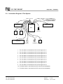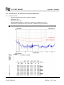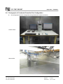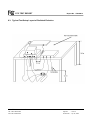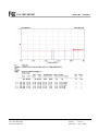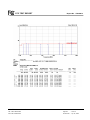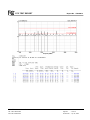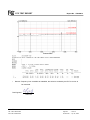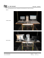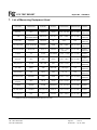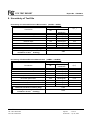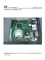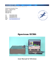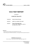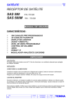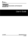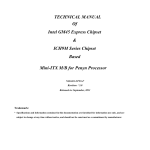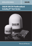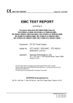
1
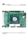
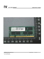
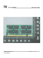
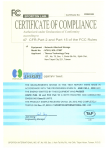
FCC TEST REPORT Report No. : FD940913 FCC TEST REPORT Authorized under Declaration of Conformity According to 47 CFR FCC Rules and Regulations Part 15 Subpart B, Class B Digital Device Equipment : IPC Boards Model No. : NF93-LF Filing Type : Declaration of Conformity Applicant : Jetway Information Co., LTD. 4F., NO. 168, LI THE ST. CHUNG HO CITY 235, TAIPEI, TAIWAN, R.O.C. The test result refers exclusively to the test presented test model / sample. Without written approval of SPORTON International Inc., the test report shall not be reproduced except in full. Certificate or Test Report must not be used by the applicant to claim the product in this test report endorsement by TAF. SPORTON International Inc. 6F, No.106, Sec. 1, Hsin Tai Wu Rd., Hsi Chih, Taipei Hsien, Taiwan, R.O.C. SPORTON International Inc. TEL : 886-2-2696-2468 FAX : 886-2-2696-2255 FCC TEST REPORT Report No. : FD940913 Table of Contents History of this test report....................................................................................................................................ii CERTIFICATE OF COMPLIANCE........................................................................................................................1 1. General Description of Equipment under Test.............................................................................................2 1.1. Applicant..........................................................................................................................................................................................2 1.2. Manufacturer ...................................................................................................................................................................................2 1.3. Basic Description of Equipment under Test ....................................................................................................................................2 1.4. Feature of Equipment under Test ...................................................................................................................................................2 2. Test Configuration of Equipment under Test ...............................................................................................3 2.1. Test Manner ....................................................................................................................................................................................3 2.2. Description of Test System .............................................................................................................................................................3 2.3. Connection Diagram of Test System ..............................................................................................................................................7 3. Test Software ...................................................................................................................................................8 4. General Information of Test............................................................................................................................9 4.1. Test Facility .....................................................................................................................................................................................9 4.2. Test Voltage ....................................................................................................................................................................................9 4.3. Standard for Methods of Measurement...........................................................................................................................................9 4.4. Test in Compliance with ..................................................................................................................................................................9 4.5. Frequency Range Investigated .......................................................................................................................................................9 4.6. Test Distance ..................................................................................................................................................................................9 5. Test of Conducted Powerline .......................................................................................................................10 5.1. Major Measuring Instruments........................................................................................................................................................10 5.2. Test Procedures ............................................................................................................................................................................10 5.3. Typical Test Setup Layout of Conducted Powerline .....................................................................................................................11 5.4. Test Result of AC Powerline Conducted Emission .......................................................................................................................12 5.5. Photographs of Conducted Powerline Test Configuration ............................................................................................................14 6. Test of Radiated Emission............................................................................................................................16 6.1. Major Measuring Instruments........................................................................................................................................................16 6.2. Test Procedures ............................................................................................................................................................................17 6.3. Typical Test Setup Layout of Radiated Emission..........................................................................................................................18 6.4. Test Result of Radiated Emission .................................................................................................................................................19 6.5. Photographs of Radiated Emission Test Configuration ................................................................................................................37 7. List of Measuring Equipment Used .............................................................................................................39 8. Uncertainty of Test Site ................................................................................................................................40 Appendix A. Photographs of EUT.......................................................................................................... A1 ~ A6 SPORTON International Inc. FCC ID : N/A TEL : 886-2-2696-2468 Page No. : i FAX : 886-2-2696-2255 Issued Date : Apr. 30, 2009 FCC TEST REPORT Report No. : FD940913 History of this test report Original Report Issue Date: Apr. 30, 2009 ■ No additional attachment. □ Additional attachment were issued as following record: Attachment No. Issue Date Description SPORTON International Inc. FCC ID : N/A TEL : 886-2-2696-2468 Page No. : ii FAX : 886-2-2696-2255 Issued Date : Apr. 30, 2009 FCC TEST REPORT Report No. : FD940913 Certificate No. : FD940913 CERTIFICATE OF COMPLIANCE Authorized under Declaration of Conformity According to 47 CFR FCC Rules and Regulations Part 15 Subpart B, Class B Digital Device Equipment : IPC Boards Model No. : NF93-LF Applicant : Jetway Information Co., LTD. 4F., NO. 168, LI THE ST. CHUNG HO CITY 235, TAIPEI, TAIWAN, R.O.C. I HEREBY CERTIFY THAT : The measurements shown in this test report were made in accordance with the procedures given in ANSI C63.4 - 2003 and the energy emitted by this equipment was passed FCC Part 15 Subpart B in both radiated and conducted emission Class B limits. Testing was carried out on Apr. 24, 2009 at SPORTON International Inc. LAB. SPORTON International Inc. 6F, No.106, Sec. 1, Hsin Tai Wu Rd., Hsi Chih, Taipei Hsien, Taiwan, R.O.C. SPORTON International Inc. FCC ID : N/A TEL : 886-2-2696-2468 Page No. : 1 of 40 FAX : 886-2-2696-2255 Issued Date : Apr. 30, 2009 FCC TEST REPORT Report No. : FD940913 1. General Description of Equipment under Test 1.1. Applicant Jetway Information Co., LTD. 4F., NO. 168, LI THE ST. CHUNG HO CITY 235, TAIPEI, TAIWAN, R.O.C. 1.2. Manufacturer Same as 1.1 1.3. Basic Description of Equipment under Test Equipment : IPC Boards Model No. : NF93-LF Trade Name : Jetway RJ45 Cable ×2 : Non-Shielded, 20 m HDMI Cable : Shielded, 2.0 m Data Cable Type : Please see section 2.2 of this test report for details Power Supply Type : Switching AC Power Cord : Non-Shielded, 1.8 m, 3 pin 1.4. Feature of Equipment under Test Please refer to user manual SPORTON International Inc. FCC ID : N/A TEL : 886-2-2696-2468 Page No. : 2 of 40 FAX : 886-2-2696-2255 Issued Date : Apr. 30, 2009 FCC TEST REPORT Report No. : FD940913 2. Test Configuration of Equipment under Test 2.1. Test Manner a. The EUT has been associated with personal computer and peripherals pursuant to ANSI C63.4-2003 and configuration operated in a manner which tended to maximize its emission characteristics in a typical application. b. The mainboard was tested in accordance with section 15.32 of the FCC rules. Testing for radiated emissions was first performed with the mainboard installed in a typical enclosure but with the enclosure's cover removed so that the internal circuitry is exposed at the top and on at least two sides. And then the EUT was tested with enclosure's cover unless it pass the required limits at first condition. c. The complete test system included remote workstation, DELL LCD Monitor, DELL USB Keyboard, DELL USB Mouse, HP Printer, ACEEX Modem, A-DATA USB 2.0 Flash Disk, i-Acon Headset, KOKA Walk Man and EUT for EMI test. The remote workstation HP Compaq PC, DELL LCD Monitor, DELL PS/2 Keyboard and HP PS/2 Mouse. The PC included INTEL CPU, DELTA Power Supply, TRANSCEND RAM and HITACHI HDD. d. The following test modes were performed for EMI test: Mode 1. CPU: 2.0GHz, DVI+VGA: 1280×1024 60Hz, LAN: 1Gbps, Close Case Mode 2. CPU: 2.0GHz, HDMI+VGA: 1280×1024 60Hz, LAN: 1Gbps, Close Case Mode 3. CPU: 2.0GHz, DVI+VGA : 1024×768 60Hz, LAN: 100Mbps, Close Case Mode 4. CPU: 2.0GHz, DVI+VGA: 1280×1024 60Hz, LAN: 1Gbps, Open Case – Only for Radiation test For Conduction test, cause “mode 1” generated the worst test result, it was reported as final data. For Radiation test, cause “mode 1 & mode 4” generated the worst test result, it was reported as final data. e. Frequency range investigated: conduction 150 kHz to 30 MHz, radiation 30 MHz to 11000MHz. 2.2. Description of Test System Support Unit 1. – LCD Monitor (DELL) – for local workstation FCC ID : N/A Model No. : 2408WFPB Power Supply Type : Switching Power Cord : Non-Shielded Serial No. : SP0026 Data Cable : Shielded, 360 degree via metal backshells, 1.8m Remark : This support device was tested to comply with FCC standards and authorized under a declaration of conformity. SPORTON International Inc. FCC ID : N/A TEL : 886-2-2696-2468 Page No. : 3 of 40 FAX : 886-2-2696-2255 Issued Date : Apr. 30, 2009 FCC TEST REPORT Report No. : FD940913 Support Unit 2. – LCD Monitor (DELL) – for local and remote workstation FCC ID : N/A Model No. : E198WFPF Power Supply Type : Switching Power Cord : Non-Shielded Serial No. : SP0027 Data Cable : Shielded, 360 degree via metal backshells, 1.8m Remark : This support device was tested to comply with FCC standards and authorized under a declaration of conformity. Support Unit 3. – USB Keyboard (DELL) – for local workstation FCC ID : N/A Model No. : SK-8115 Serial No. : SP0001 Data Cable : Shielded, 2.0m Remark : This support device was tested to comply with FCC standards and authorized under a declaration of conformity. Support Unit 4. – PS/2 Mouse (DELL) – for local workstation FCC ID : N/A Model No. : MO56UO Serial No. : SP0010 Data Cable : Shielded, 1.8m Remark : This support device was tested to comply with FCC standards and authorized under a declaration of conformity. Support Unit 5. -- Modem (ACEEX) – for local workstation FCC ID : IFAXDM1414 Model No. : DM1414 Power Supply Type : Linear Power Cord : Non-Shielded Serial No. : SP0065 Data Cable : Shielded, 360 degree via metal backshells, 1.15m SPORTON International Inc. FCC ID : N/A TEL : 886-2-2696-2468 Page No. : 4 of 40 FAX : 886-2-2696-2255 Issued Date : Apr. 30, 2009 FCC TEST REPORT Report No. : FD940913 Support Unit 6. -- USB 2.0 Flash (ADATA) – for local workstation FCC ID : N/A Model No. : PD4 Serial No. : SP0075 Data Cable : Shielded, 0.5m Support Unit 7. -- Headset (i-Acon) – for local workstation FCC ID : N/A Model No. : HOH-323-BK Serial No. : SP0074 Data Cable : Non-Shielded, 2.0m Support Unit 8. – Walkman (KOKA) – for local workstation FCC ID : N/A Model No. : KW-246 Serial No. : SP0067 Data Cable : Non-Shielded, 1.7m Support Unit 9. -- Personal Computer (hp Compaq) – for remote workstation FCC ID : N/A Model No. : D330uT Power Supply Type : Switching Power Cord : Non-Shielded Serial No. : SP0047 Remark : This support device was tested to comply with FCC standards and authorized under a declaration of conformity. Support Unit 10. -- PS/2 Keyboard (HP) – for remote workstation FCC ID : N/A Model No. : KB-0133 Serial No. : SP0054 Data Cable : Shielded, 1.9m Remark : This support device was tested to comply with FCC standards and authorized under a declaration of conformity. SPORTON International Inc. FCC ID : N/A TEL : 886-2-2696-2468 Page No. : 5 of 40 FAX : 886-2-2696-2255 Issued Date : Apr. 30, 2009 FCC TEST REPORT Report No. : FD940913 Support Unit 11. -- PS/2 Mouse (HP) – for remote workstation FCC ID : JNZ211443 Model No. : M-S69 Serial No. : SP0035 Data Cable : Non-Shielded, 1.85m Support Unit 12. -- CPU (INTEL) – for local workstation Model No. : 2G Serial No. : SP0151 .Support Unit 13. -- RAM (TRANSCEND) – for local workstation Spec. : 2G Serial No. : SP0117 .Support Unit 14. – HDD (HITACHI) – for local workstation Model No. : 80G Serial No. : SP0119 Support Unit 15. -- Power Supply (DELTA) Model No. : DPS-300AB-39B Serial No. : SP0150 SPORTON International Inc. FCC ID : N/A TEL : 886-2-2696-2468 Page No. : 6 of 40 FAX : 886-2-2696-2255 Issued Date : Apr. 30, 2009 FCC TEST REPORT Report No. : FD940913 2.3. Connection Diagram of Test System USB2.0 Flash Disk 10 Remote workstation 11 Remote workstation 1 2 LCD Monitor LCD Monitor 7 EUT 5 6 Modem USB2.0 Flash Disk Modem 3 4 8 9 Keyboard Mouse Headset Walkman 1. The I/O cable is connected from EUT to the support unit 1. 2. The I/O cable is connected from EUT to the support unit 2. 3. The I/O cable is connected from EUT to the support unit 3. 4. The I/O cable is connected from EUT to the support unit 4. 5. The I/O cable is connected from EUT to the support unit 5. 6. The I/O cable is connected from EUT to the support unit 5. 7. The I/O cable is connected from EUT to the support unit 6. 8. The I/O cable is connected from EUT to the support unit 7. 9. The I/O cable is connected from EUT to the support unit 8. 10. The RJ45 cable is connected from EUT to the remote workstation. 11. The RJ45 cable is connected from EUT to the remote workstation. SPORTON International Inc. FCC ID : N/A TEL : 886-2-2696-2468 Page No. : 7 of 40 FAX : 886-2-2696-2255 Issued Date : Apr. 30, 2009 FCC TEST REPORT Report No. : FD940913 3. Test Software An executive program, “EMCTEST.EXE” under WIN XP, which generates a complete line of continuously repeating “ H “ pattern was used as the test software. The program was executed as follows : a. Turn on the power of all equipment. b. The PC reads the test program from the hard disk drive and runs it. c. The PC sends “ H “ messages to the monitor, and the monitor displays “ H “ patterns on the screen. d. The PC sends “ H “ messages to the modem. e. The PC sends “ H ” messages to the internal Hard Disk, and the Hard Disk reads and writes the message. f. Repeat the steps from c to e. At the same time, the following test programs were executed: - Executed “MEDIA PLAYER” to play music. - Executed “PING.EXE” to link with the remote workstation to receive and transmit data by RJ45 cable. - Executed “Winthrax.exe” to read and write data from external USB2.0 Flash Disk. SPORTON International Inc. FCC ID : N/A TEL : 886-2-2696-2468 Page No. : 8 of 40 FAX : 886-2-2696-2255 Issued Date : Apr. 30, 2009 FCC TEST REPORT Report No. : FD940913 4. General Information of Test 4.1. Test Facility Test Site Location Test Site No. Test Site Location Test Site No. : No. 3, Lane 238, Kang Lo Street, Nei Hwu District, Taipei 11424, Taiwan, R.O.C. TEL : 886-2-2631-4739 FAX : 886-2-2631-9740 : CO01-NH, OS02-NH : No. 52, Hwa Ya 1St Road, Hwa Ya Technology Park, Kwei-Shan Hsiang, TaoYuan Hsien, Taiwan, R.O.C. TEL : 886-3-3273456 FAX : 886-3-3180055 : 03CH04-HY 4.2. Test Voltage 120V / 60Hz 4.3. Standard for Methods of Measurement ANSI C63.4-2003 4.4. Test in Compliance with FCC Rules and Regulations Part 15 Subpart B 4.5. Frequency Range Investigated a. Conduction: from 150 kHz to 30 MHz b. Radiation: from 30 MHz to 11000 MHz 4.6. Test Distance a. The test distance of radiated emission from antenna to EUT is 10M (from 30MHz~1000MHz). b. The test distance of radiated emission from antenna to EUT is 3 M (from 1GHz~9GHz). c. The test distance of radiated emission from antenna to EUT is 1 M (from 9GHz~11GHz). SPORTON International Inc. FCC ID : N/A TEL : 886-2-2696-2468 Page No. : 9 of 40 FAX : 886-2-2696-2255 Issued Date : Apr. 30, 2009 FCC TEST REPORT Report No. : FD940913 5. Test of Conducted Powerline Conducted Emissions were measured from 150 kHz to 30 MHz with a bandwidth of 9 kHz and return leads of the EUT according to the methods defined in ANSI C63.4-2003 Section 3.1. The EUT was placed on a nonmetallic stand in a shielded room 0.8 meters above the ground plane as shown in section 5.3. The interface cables and equipment positioning were varied within limits of reasonable applications to determine the position produced maximum conducted emissions. 5.1. Major Measuring Instruments z Test Receiver ( R&S ESCS 30 ) Attenuation 10 dB Start Frequency 0.15 MHz Stop Frequency 30 MHz IF Bandwidth 9 kHz 5.2. Test Procedures a. The EUT was placed 0.4 meter from the conducting wall of the shielding room was kept at least 80 centimeters from any other grounded conducting surface. b. Connect EUT to the power mains through a line impedance stabilization network (LISN). c. All the support units are connect to the other LISN. d. The LISN provides 50 ohm coupling impedance for the measuring instrument. e. The FCC states that a 50 ohm, 50 microhenry LISN should be used. f. Both sides of AC line were checked for maximum conducted interference. g. The frequency range from 150 kHz to 30 MHz was searched. h. Set the test-receiver system to Peak Detect Function and Specified Bandwidth with Maximum Hold Mode. SPORTON International Inc. FCC ID : N/A TEL : 886-2-2696-2468 Page No. : 10 of 40 FAX : 886-2-2696-2255 Issued Date : Apr. 30, 2009 FCC TEST REPORT Report No. : FD940913 5.3. Typical Test Setup Layout of Conducted Powerline SPORTON International Inc. FCC ID : N/A TEL : 886-2-2696-2468 Page No. : 11 of 40 FAX : 886-2-2696-2255 Issued Date : Apr. 30, 2009 FCC TEST REPORT Report No. : FD940913 5.4. Test Result of AC Powerline Conducted Emission 5.4.1. Test Mode: Mode 1 Frequency Range of Test: from 0.15 MHz to 30 MHz Temperature: 22 ℃ Relative Humidity: 52 % Corrected Reading (dBuV) = LISN Loss + Cable Loss + Read Level = Level All emissions not reported here are more than 10 dB below the prescribed limit. ■ The test was passed at the minimum margin that marked by a frame in the following table SPORTON International Inc. FCC ID : N/A TEL : 886-2-2696-2468 Page No. : 12 of 40 FAX : 886-2-2696-2255 Issued Date : Apr. 30, 2009 FCC TEST REPORT Report No. : FD940913 Test Engineer : Eddie Lee SPORTON International Inc. FCC ID : N/A TEL : 886-2-2696-2468 Page No. : 13 of 40 FAX : 886-2-2696-2255 Issued Date : Apr. 30, 2009 FCC TEST REPORT Report No. : FD940913 5.5. Photographs of Conducted Powerline Test Configuration z The photographs show the configuration that generates the maximum emission. FRONT VIEW REAR VIEW SPORTON International Inc. FCC ID : N/A TEL : 886-2-2696-2468 Page No. : 14 of 40 FAX : 886-2-2696-2255 Issued Date : Apr. 30, 2009 FCC TEST REPORT Report No. : FD940913 SIDE VIEW SPORTON International Inc. FCC ID : N/A TEL : 886-2-2696-2468 Page No. : 15 of 40 FAX : 886-2-2696-2255 Issued Date : Apr. 30, 2009 FCC TEST REPORT Report No. : FD940913 6. Test of Radiated Emission Radiated emissions from 30 MHz to 11000 MHz were measured with a bandwidth of 120 kHz for 30 MHz to 1000 MHz and 1 MHz for above 1GHz according to the methods defines in ANSI C63.4-2003. The EUT was placed on a nonmetallic stand, 0.8 meter above the ground plane, as shown in section 6.3. The interface cables and equipment positions were varied within limits of reasonable applications to determine the positions producing maximum radiated emissions. 6.1. Major Measuring Instruments 6.1.1. For 30MHz to 1GHz z z Amplifier ( HP 8447D ) RF Gain 25 dB Signal Input 0.1 MHz - 1.3 GHz Test Receiver ( R&S ESCI ) Resolution Bandwidth 120 kHz Frequency Band 9 kHz - 3 GHz Quasi-Peak Detector ON for Quasi-Peak Mode OFF for Peak Mode 6.1.2. For 1GHz to 11GHz z z Amplifier ( Agilent 8449B ) RF Gain 35 dB Signal Input 1 GHz - 26.5 GHz Spectrum Analyzer ( R&S FSP40 ) Attenuation 10 dB Start Frequency 1 GHz Stop Frequency 11 GHz Resolution Bandwidth 1 MHz Video Bandwidth 1 MHz Signal Input 9 kHz - 40 GHz SPORTON International Inc. FCC ID : N/A TEL : 886-2-2696-2468 Page No. : 16 of 40 FAX : 886-2-2696-2255 Issued Date : Apr. 30, 2009 FCC TEST REPORT Report No. : FD940913 6.2. Test Procedures a. The EUT was placed on a rotatable table top 0.8 meter above ground. b. The EUT was set 1/3/10 meters from the interference receiving antenna which was mounted on the top of a variable height antenna tower. c. The table was rotated 360 degrees to determine the position of the highest radiation. d. The antenna is a half wave dipole and its height is varied between one meter and four meters above ground to find the maximum value of the field strength both horizontal polarization and vertical polarization of the antenna are set to make the measurement. e. For each suspected emission the EUT was arranged to its worst case and then tune the antenna tower (from 1 M to 4 M) and turn table (from 0 degree to 360 degrees) to find the maximum reading. f. Set the test-receiver system to Peak Detect Function and specified bandwidth with Maximum Hold Mode. g. If the emission level of the EUT in peak mode was 3 dB lower than the limit specified, then testing will be stopped and peak values of EUT will be reported, otherwise, the emissions which do not have 3 dB margin will be repeated one by one using the quasi-peak method and reported. SPORTON International Inc. FCC ID : N/A TEL : 886-2-2696-2468 Page No. : 17 of 40 FAX : 886-2-2696-2255 Issued Date : Apr. 30, 2009 FCC TEST REPORT Report No. : FD940913 6.3. Typical Test Setup Layout of Radiated Emission SPORTON International Inc. FCC ID : N/A TEL : 886-2-2696-2468 Page No. : 18 of 40 FAX : 886-2-2696-2255 Issued Date : Apr. 30, 2009 FCC TEST REPORT Report No. : FD940913 6.4. Test Result of Radiated Emission 6.4.1. Test Mode: Mode 1 Frequency Range of Test: from 30 MHz to 11,000 MHz Temperature: 24 ℃ Relative Humidity: 57 % Emission level (dBuV/m) = 20 log Emission level (uV/m) Corrected Reading: Antenna Factor + Cable Loss + Read Level - Preamp Factor = Level ■ The test was passed at the minimum margin that marked by the frame in the following table y Test Distance: 10M for 30MHz ~ 1GHz SPORTON International Inc. FCC ID : N/A TEL : 886-2-2696-2468 Page No. : 19 of 40 FAX : 886-2-2696-2255 Issued Date : Apr. 30, 2009 FCC TEST REPORT Report No. : FD940913 SPORTON International Inc. FCC ID : N/A TEL : 886-2-2696-2468 Page No. : 20 of 40 FAX : 886-2-2696-2255 Issued Date : Apr. 30, 2009 FCC TEST REPORT Report No. : FD940913 SPORTON International Inc. FCC ID : N/A TEL : 886-2-2696-2468 Page No. : 21 of 40 FAX : 886-2-2696-2255 Issued Date : Apr. 30, 2009 FCC TEST REPORT Report No. : FD940913 SPORTON International Inc. FCC ID : N/A TEL : 886-2-2696-2468 Page No. : 22 of 40 FAX : 886-2-2696-2255 Issued Date : Apr. 30, 2009 FCC TEST REPORT y Report No. : FD940913 Test Distance: 3M from 1000 MHz ~ 9000 MHz, 1M from 9000 MHz ~ 11000 MHz SPORTON International Inc. FCC ID : N/A TEL : 886-2-2696-2468 Page No. : 23 of 40 FAX : 886-2-2696-2255 Issued Date : Apr. 30, 2009 FCC TEST REPORT Report No. : FD940913 SPORTON International Inc. FCC ID : N/A TEL : 886-2-2696-2468 Page No. : 24 of 40 FAX : 886-2-2696-2255 Issued Date : Apr. 30, 2009 FCC TEST REPORT Report No. : FD940913 SPORTON International Inc. FCC ID : N/A TEL : 886-2-2696-2468 Page No. : 25 of 40 FAX : 886-2-2696-2255 Issued Date : Apr. 30, 2009 FCC TEST REPORT y Report No. : FD940913 Remark: Frequency from 5000MHz to 11000MHz, the emission emitted by the EUT is too low to be measured. Test Engineer: Chas Yeh SPORTON International Inc. FCC ID : N/A TEL : 886-2-2696-2468 Page No. : 26 of 40 FAX : 886-2-2696-2255 Issued Date : Apr. 30, 2009 FCC TEST REPORT Report No. : FD940913 6.4.2. Test Mode: Mode 4 The mainboard was tested in accordance with section 15.32 of the FCC rules. Testing for radiated emissions was first performed with the mainboard installed in a typical enclosure but with the enclosure's cover removed so that the internal circuitry is exposed at the top and on at least two sides. And then the EUT was tested with enclosure's cover unless it pass the required limits at first condition Frequency Range of Test: from 30 MHz to 11,000 MHz Temperature: 24 ℃ Relative Humidity: 57 % Emission level (dBuV/m) = 20 log Emission level (uV/m) Corrected Reading: Antenna Factor + Cable Loss + Read Level - Preamp Factor = Level ■ The test was passed at the minimum margin that marked by the frame in the following table y Test Distance: 10M for 30MHz ~ 1GHz SPORTON International Inc. FCC ID : N/A TEL : 886-2-2696-2468 Page No. : 27 of 40 FAX : 886-2-2696-2255 Issued Date : Apr. 30, 2009 FCC TEST REPORT Report No. : FD940913 SPORTON International Inc. FCC ID : N/A TEL : 886-2-2696-2468 Page No. : 28 of 40 FAX : 886-2-2696-2255 Issued Date : Apr. 30, 2009 FCC TEST REPORT Report No. : FD940913 SPORTON International Inc. FCC ID : N/A TEL : 886-2-2696-2468 Page No. : 29 of 40 FAX : 886-2-2696-2255 Issued Date : Apr. 30, 2009 FCC TEST REPORT Report No. : FD940913 SPORTON International Inc. FCC ID : N/A TEL : 886-2-2696-2468 Page No. : 30 of 40 FAX : 886-2-2696-2255 Issued Date : Apr. 30, 2009 FCC TEST REPORT y Report No. : FD940913 Test Distance: 3M from 1000 MHz ~ 9000 MHz, 1M from 9000 MHz ~ 11000 MHz SPORTON International Inc. FCC ID : N/A TEL : 886-2-2696-2468 Page No. : 31 of 40 FAX : 886-2-2696-2255 Issued Date : Apr. 30, 2009 FCC TEST REPORT Report No. : FD940913 SPORTON International Inc. FCC ID : N/A TEL : 886-2-2696-2468 Page No. : 32 of 40 FAX : 886-2-2696-2255 Issued Date : Apr. 30, 2009 FCC TEST REPORT Report No. : FD940913 SPORTON International Inc. FCC ID : N/A TEL : 886-2-2696-2468 Page No. : 33 of 40 FAX : 886-2-2696-2255 Issued Date : Apr. 30, 2009 FCC TEST REPORT Report No. : FD940913 SPORTON International Inc. FCC ID : N/A TEL : 886-2-2696-2468 Page No. : 34 of 40 FAX : 886-2-2696-2255 Issued Date : Apr. 30, 2009 FCC TEST REPORT Report No. : FD940913 SPORTON International Inc. FCC ID : N/A TEL : 886-2-2696-2468 Page No. : 35 of 40 FAX : 886-2-2696-2255 Issued Date : Apr. 30, 2009 FCC TEST REPORT y Report No. : FD940913 Remark: Frequency from 7000MHz to 9000MHz, the emission emitted by the EUT is too low to be measured. Test Engineer: Chas Yeh SPORTON International Inc. FCC ID : N/A TEL : 886-2-2696-2468 Page No. : 36 of 40 FAX : 886-2-2696-2255 Issued Date : Apr. 30, 2009 FCC TEST REPORT Report No. : FD940913 6.5. Photographs of Radiated Emission Test Configuration z The photographs show the configuration that generates the maximum emission. Mode 1 FRONT VIEW REAR VIEW SPORTON International Inc. FCC ID : N/A TEL : 886-2-2696-2468 Page No. : 37 of 40 FAX : 886-2-2696-2255 Issued Date : Apr. 30, 2009 FCC TEST REPORT z Report No. : FD940913 The photographs show the configuration that generates the maximum emission. Mode 4 FRONT VIEW REAR VIEW SPORTON International Inc. FCC ID : N/A TEL : 886-2-2696-2468 Page No. : 38 of 40 FAX : 886-2-2696-2255 Issued Date : Apr. 30, 2009 FCC TEST REPORT Report No. : FD940913 7. List of Measuring Equipment Used Instrument Manufacturer Model No. Serial No. Characteristics Calibration Date Receiver R&S ESCS 30 100357 9 kHz - 2.75 GHz Nov. 13, 2008 NSLK 8127 8127-477 9kHz – 30MHz Nov. 26, 2008 LISN SCHWARZBECK MESS-ELEKTRONIK Remark Conduction (CO01-NH) Conduction (CO01-NH) Conduction Power Filter CORCOM MR12030 N/A 30A*2 N/A RF Cable-CON Suhner Switzerland RG223/U CB004 9kHz – 30MHz Dec. 16, 2008 Open Area Test Site SPORTON OATS-10 OS02-NH Amplifier HP 8447D 2944A09068 0.1 MHz - 1.3 GHz Nov. 10, 2008 Receiver R&S ESCI 100497 9 kHz – 3 GHz Feb. 19, 2009 Bilog Antenna CHASE CBL6122B 2884 30 MHz - 2 GHz Dec. 27, 2008 Turn Table EMCO 2080 9508-1805 0 - 360 degree N/A Antenna Mast ETS 2075-2 2385 1m-4m N/A RF Cable-R10m MIYAZAKI 5DFB CB002 30 MHz - 1 GHz Sep. 18, 2008 R&S FSP40 100793 9 kHz - 30 GHz Aug. 25, 2008 Radiation Amplifier AGILENT 8449B 3008A02373 1 GHz - 26.5 GHz Jul. 16, 2008 Radiation RF Cable-HIGH SUHNER SUCOFLEX 106 CB063-HF 1 GHz - 40 GHz Nov. 29, 2008 Radiation Horn Antenna ETS 3117 00075954 1GHz ~ 18GHz Apr. 25, 2008 Radiation Spectrum Analyzer 30 MHz - 1 GHz 10m, 3m Jan. 04, 2009 (CO01-NH) Conduction (CO01-NH) Radiation (OS02-NH) Radiation (OS02-NH) Radiation (OS02-NH) Radiation (OS02-NH) Radiation (OS02-NH) Radiation (OS02-NH) Radiation (OS02-NH) ※ Calibration Interval of instruments listed above is one year. SPORTON International Inc. FCC ID : N/A TEL : 886-2-2696-2468 Page No. : 39 of 40 FAX : 886-2-2696-2255 Issued Date : Apr. 30, 2009 FCC TEST REPORT Report No. : FD940913 8. Uncertainty of Test Site Uncertainty of Conducted Emission Measurement (150kHz ~ 30MHz) Uncertainty of Contribution xi u ( xi ) dB Probability Distribution Receiver reading 0.20 Normal(k=2) 0.10 Cable loss 0.19 Normal(k=2) 0.10 AMN insertion loss 2.50 Rectangular 0.63 Receiver Spec 1.50 Rectangular 0.43 Site imperfection 1.75 Rectangular 1.01 Mismatch +0.44/-0.46 U-shape 0.32 combined standard uncertainty Uc(y) 1.31 Measuring uncertainty for a level of confidence of 95% U=2Uc(y) 2.62 Uncertainty of Radiated Emission Measurement (30MHz ~ 1000MHz) Uncertainty of xi u ( xi ) dB Probability Distribution Receiver reading 0.27 Normal(k=2) 0.14 Antenna factor calibration 0.92 Normal(k=2) 0.46 Contribution Cable loss calibration 0.16 Normal(k=2) 0.08 Pre Amplifier Gain calibration 0.17 Normal(k=2) 0.09 RCV/SPA specification 2.50 Rectangular 0.72 Antenna Factor Interpolation for Frequency 1.00 Rectangular 0.29 Site imperfection 1.99 Rectangular 1.15 Mismatch +0.50/-0.54 U-shaped 0.37 combined standard uncertainty Uc(y) 1.52 Measuring uncertainty for a level of confidence of 95% U=2Uc(y) 3.04 SPORTON International Inc. FCC ID : N/A TEL : 886-2-2696-2468 Page No. : 40 of 40 FAX : 886-2-2696-2255 Issued Date : Apr. 30, 2009 FCC TEST REPORT REPORT NO.: FD940913 APPENDIX A. Photographs of EUT SPORTON International Inc. TEL : 886-2-2696-2468 FAX : 886-2-2696-2255 Page Number : A1 of A6 FCC TEST REPORT SPORTON International Inc. TEL : 886-2-2696-2468 FAX : 886-2-2696-2255 REPORT NO.: FD940913 Page Number : A2 of A6 FCC TEST REPORT SPORTON International Inc. TEL : 886-2-2696-2468 FAX : 886-2-2696-2255 REPORT NO.: FD940913 Page Number : A3 of A6 FCC TEST REPORT SPORTON International Inc. TEL : 886-2-2696-2468 FAX : 886-2-2696-2255 REPORT NO.: FD940913 Page Number : A4 of A6 FCC TEST REPORT SPORTON International Inc. TEL : 886-2-2696-2468 FAX : 886-2-2696-2255 REPORT NO.: FD940913 Page Number : A5 of A6 FCC TEST REPORT SPORTON International Inc. TEL : 886-2-2696-2468 FAX : 886-2-2696-2255 REPORT NO.: FD940913 Page Number : A6 of A6