1
SIMATIC HMI HMI device KTP400 Basic, KTP600 Basic, KTP1000 Basic, TP1500 Basic
Preface
1
Overview
______________
SIMATIC HMI
HMI device
KTP400 Basic, KTP600 Basic,
KTP1000 Basic, TP1500 Basic
Operating Instructions
Safety instructions and
general notes
2
______________
3
Mounting and connecting
______________
4
Operating the user interface
______________
Configuring the operating
system
5
______________
6
Commissioning a project
______________
7
Maintenance and care
______________
8
Technical specifications
______________
A
Appendix
______________
B
Abbreviations
______________
01/2009
A5E02421799-01
Legal information
Legal information
Warning notice system
This manual contains notices you have to observe in order to ensure your personal safety, as well as to prevent
damage to property. The notices referring to your personal safety are highlighted in the manual by a safety alert
symbol, notices referring only to property damage have no safety alert symbol. These notices shown below are
graded according to the degree of danger.
DANGER
indicates that death or severe personal injury will result if proper precautions are not taken.
WARNING
indicates that death or severe personal injury may result if proper precautions are not taken.
CAUTION
with a safety alert symbol, indicates that minor personal injury can result if proper precautions are not taken.
CAUTION
without a safety alert symbol, indicates that property damage can result if proper precautions are not taken.
NOTICE
indicates that an unintended result or situation can occur if the corresponding information is not taken into
account.
If more than one degree of danger is present, the warning notice representing the highest degree of danger will
be used. A notice warning of injury to persons with a safety alert symbol may also include a warning relating to
property damage.
Qualified Personnel
The device/system may only be set up and used in conjunction with this documentation. Commissioning and
operation of a device/system may only be performed by qualified personnel. Within the context of the safety notes
in this documentation qualified persons are defined as persons who are authorized to commission, ground and
label devices, systems and circuits in accordance with established safety practices and standards.
Proper use of Siemens products
Note the following:
WARNING
Siemens products may only be used for the applications described in the catalog and in the relevant technical
documentation. If products and components from other manufacturers are used, these must be recommended
or approved by Siemens. Proper transport, storage, installation, assembly, commissioning, operation and
maintenance are required to ensure that the products operate safely and without any problems. The permissible
ambient conditions must be adhered to. The information in the relevant documentation must be observed.
Trademarks
All names identified by ® are registered trademarks of the Siemens AG. The remaining trademarks in this
publication may be trademarks whose use by third parties for their own purposes could violate the rights of the
owner.
Disclaimer of Liability
We have reviewed the contents of this publication to ensure consistency with the hardware and software
described. Since variance cannot be precluded entirely, we cannot guarantee full consistency. However, the
information in this publication is reviewed regularly and any necessary corrections are included in subsequent
editions.
Siemens AG
Industry Sector
Postfach 48 48
90026 NÜRNBERG
GERMANY
A5E02421799-01
Ⓟ 01/2009
Copyright © Siemens AG 2009.
Technical data subject to change
Preface
Purpose of the operating instructions
These operating instructions provide information based on the requirements defined by
IEC 62079 for documentation. This information relates to the HMI device, its storage,
transportation, place of use, installation, use and maintenance.
These operating instructions are intended for a variety of target groups. The following table
shows the sections of these operating instructions that are of particular importance for the
respective target group.
Target group
Section
All
"Safety instructions"
Operators
"Overview"
The operator operates and monitors the system
during the process control phase.
"Operating a project"
Commissioning engineers
All sections.
The commissioning engineer integrates the HMI
device into the system and ensures the operating
capability of the HMI device for the process control
phase.
Depending on the use of the HMI device,
certain chapters may not be of relevance to the
commissioning engineer, e.g. the section
"Maintenance and servicing."
Service technicians
All sections.
Service technicians rectify faults that occur during
the process control phase.
Depending on the use of the HMI device,
certain sections may not be of relevance to the
service technicians, e.g. the section
"Maintenance and servicing."
Maintenance technicians
Maintenance and care
Maintenance technicians carry out servicing and
maintenance work during the process control
phase.
The help integrated in WinCC flexible, the WinCC flexible Information System, contains
detailed information. The WinCC flexible Information System contains instructions, examples
and reference information in electronic form.
Scope of the operating instructions
The operating instructions apply to the HMI devices KTP400 Basic, KTP600 Basic,
KTP1000 Basic and TP1500 Basic in combination with the WinCC flexible software package.
Basic knowledge required
Knowledge of automation technology and process communication is necessary to
understand the operating instructions.
An understanding of the use of computers and operating systems is also required.
KTP400 Basic, KTP600 Basic, KTP1000 Basic, TP1500 Basic
Operating Instructions, 01/2009, A5E02421799-01
3
Preface
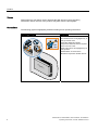
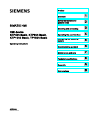
Photos
Photographs are sometimes used to illustrate the HMI devices in these operating
instructions. Newer versions of the products may differ from the photographs.
Conventions
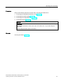
The following graphical highlighting facilitates reading these operating instructions:
Graphical highlighting
Description
If the instructions involve several tasks,
the individual tasks are highlighted by an
orange number circle.
ื 0.2
Nm
A light blue highlight indicates
components and tools that are required
in the course of a task.
Safety instructions are highlighted by an
orange frame.
KTP600 Basic as shown in the
illustrations represents all HMI devices.
.7
3
4
KTP400 Basic, KTP600 Basic, KTP1000 Basic, TP1500 Basic
Operating Instructions, 01/2009, A5E02421799-01
Preface
The following text highlighting facilitates reading these operating instructions:
Text highlighting
Scope
"Add screen"
•
•
•
Terms that appear in the user interface, for example, dialog
names, tabs, buttons, menu commands
Input values, for example, limits, tag values
Path information
"File > Edit"
Operational sequences, for example, menu commands, shortcut
menu commands
<F1>
Keyboard operation
Configuration and runtime software differ with regard to their names as follows:
● "WinCC flexible 2008", for example, refers to the configuration software.
The term "WinCC flexible" is used in a general context. The full name, for example,
"WinCC flexible 2008", is always used when it is necessary to differentiate between
different versions of the configuration software.
● "WinCC flexible Runtime" refers to the runtime software that can run on HMI devices.
Note information highlighted as follows:
Note
A note contains important information on described products and their handling or on a
section of this documentation.
Trademarks
Names labeled with a ® symbol are registered trademarks of the Siemens AG. Other names
used in this documentation may be trademarks, the use of which by third parties for their
own purposes could violate the rights of the owner.
● HMI®
● SIMATIC®
● SIMATIC HMI®
● SIMATIC ProTool®
● WinCC®
● SIMATIC WinCC flexible®
KTP400 Basic, KTP600 Basic, KTP1000 Basic, TP1500 Basic
Operating Instructions, 01/2009, A5E02421799-01
5
Preface
Additional information
You can find additional information about products described in the manual under "Contact"
in the following table:
6
Request
Contact
Contact persons and office locations
"http://www.siemens.com/automation/partner"
Additional technical documentation
"http://www.automation.siemens.com/portal/index.htm"
Training Center
"http://sitrain.automation.siemens.com/sitrain/"
Technical Support
"http://support.automation.siemens.com"
Online support request form
"http://www.siemens.com/automation/support-request"
Service
"http://www.siemens.com/automation/service"
KTP400 Basic, KTP600 Basic, KTP1000 Basic, TP1500 Basic
Operating Instructions, 01/2009, A5E02421799-01
Table of contents
Preface ...................................................................................................................................................... 3
1
2
3
4
Overview.................................................................................................................................................. 11
1.1
Product Overview.........................................................................................................................11
1.2
Design of the KTP400 Basic ........................................................................................................12
1.3
Design of the KTP600 DP Basic ..................................................................................................13
1.4
Design of the KTP600 PN Basic ..................................................................................................14
1.5
Design of the KTP1000 DP Basic ................................................................................................15
1.6
Design of the KTP1000 PN Basic ................................................................................................16
1.7
Design of the TP1500 Basic ........................................................................................................17
1.8
Product package ..........................................................................................................................18
1.9
Accessories..................................................................................................................................19
1.10
Commissioning the HMI device ...................................................................................................20
Safety instructions and general notes ...................................................................................................... 21
2.1
Safety instructions........................................................................................................................21
2.2
Notes about usage.......................................................................................................................22
Mounting and connecting......................................................................................................................... 23
3.1
3.1.1
3.1.2
3.1.3
3.1.4
3.1.5
3.1.6
Preparations.................................................................................................................................23
Checking the package contents...................................................................................................23
Checking the operating conditions...............................................................................................23
Selecting a mounting position ......................................................................................................24
Checking clearances....................................................................................................................25
Making the mounting cut-out........................................................................................................25
Labeling the function keys ...........................................................................................................27
3.2
Mounting the HMI device .............................................................................................................28
3.3
3.3.1
3.3.2
3.3.3
3.3.4
3.3.5
3.3.6
Connecting the HMI device..........................................................................................................30
Connection sequence ..................................................................................................................30
Connecting the equipotential bonding circuit ...............................................................................32
Connecting the power supply.......................................................................................................34
Connecting a programming device ..............................................................................................35
Connecting the configuration PC .................................................................................................36
Connecting the PLC.....................................................................................................................39
3.4
Switching on and testing the HMI device.....................................................................................42
3.5
Securing the cables .....................................................................................................................43
Operating the user interface .................................................................................................................... 45
4.1
Overview ......................................................................................................................................45
4.2
General functions of the screen keyboard ...................................................................................47
4.3
Entering data on the KTP400 Basic.............................................................................................48
4.4
Entering data on the KTP600, KTP1000, TP1500 Basic.............................................................51
KTP400 Basic, KTP600 Basic, KTP1000 Basic, TP1500 Basic
Operating Instructions, 01/2009, A5E02421799-01
7
Table of contents
5
6
7
8
Configuring the operating system ............................................................................................................ 53
5.1
Opening the Control Panel.......................................................................................................... 53
5.2
Overview ..................................................................................................................................... 54
5.3
Changing MPI/DP settings .......................................................................................................... 55
5.4
Changing the network configuration ........................................................................................... 56
5.5
Changing monitor settings .......................................................................................................... 57
5.6
Displaying information about the HMI device.............................................................................. 58
5.7
Calibrating the touch screen ....................................................................................................... 59
5.8
Displaying licensing information for the HMI device ................................................................... 60
5.9
Enabling a data channel.............................................................................................................. 61
5.10
Changing password settings....................................................................................................... 63
5.11
Setting the Screen Saver ............................................................................................................ 64
5.12
Setting acoustic signals............................................................................................................... 64
Commissioning a project ......................................................................................................................... 65
6.1
Overview ..................................................................................................................................... 65
6.2
Operating modes......................................................................................................................... 66
6.3
Data transmission options........................................................................................................... 67
6.4
6.4.1
6.4.2
6.4.3
6.4.4
Transfer ....................................................................................................................................... 67
Overview ..................................................................................................................................... 67
Starting manual transfer.............................................................................................................. 67
Starting automatic transfer .......................................................................................................... 68
Testing a project.......................................................................................................................... 69
6.5
6.5.1
6.5.2
6.5.3
Backup and restore ..................................................................................................................... 71
Overview ..................................................................................................................................... 71
Backup and restore using WinCC flexible................................................................................... 72
Backup and restore using ProSave ............................................................................................ 74
6.6
6.6.1
6.6.2
6.6.3
6.6.4
OS update - Basic Panel DP....................................................................................................... 76
Overview ..................................................................................................................................... 76
Resetting factory settings............................................................................................................ 77
Updating the Operating System using WinCC flexible ............................................................... 77
Updating the Operating System using ProSave ......................................................................... 79
6.7
6.7.1
6.7.2
6.7.3
6.7.4
6.7.5
6.7.6
OS update - Basic Panel PN....................................................................................................... 80
Overview ..................................................................................................................................... 80
Resetting factory settings............................................................................................................ 81
Updating the operating system using WinCC flexible................................................................. 82
Updating the operating system using ProSave........................................................................... 83
Resetting to factory settings with WinCC flexible ....................................................................... 84
Resetting to factory settings with ProSave ................................................................................. 86
Maintenance and care ............................................................................................................................. 89
7.1
Maintenance and care................................................................................................................. 89
7.2
Recycling..................................................................................................................................... 90
KTP400 Basic, KTP600 Basic, KTP1000 Basic, TP1500 Basic
Operating Instructions, 01/2009, A5E02421799-01
Table of contents
8
A
B
Technical specifications........................................................................................................................... 91
8.1
Standards, certificates and approvals..........................................................................................91
8.2
Electromagnetic compatibility ......................................................................................................92
8.3
Transport and storage conditions ................................................................................................94
8.4
Conditions of use .........................................................................................................................95
8.5
Information on insulation tests, protection class and degree of protection..................................97
8.6
Power supply................................................................................................................................98
8.7
8.7.1
8.7.2
8.7.3
8.7.4
8.7.5
8.7.6
Dimension drawings.....................................................................................................................99
Dimensional drawing of KTP400 Basic........................................................................................99
Dimensional drawing of KTP600 DP Basic................................................................................100
Dimensional drawing of KTP600 PN Basic................................................................................101
Dimensional drawing of KTP1000 DP Basic..............................................................................102
Dimensional drawing of KTP1000 PN Basic..............................................................................103
Dimensional drawing of TP1500 Basic ......................................................................................104
8.8
8.8.1
8.8.2
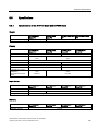
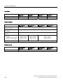
Specifications .............................................................................................................................105
Specifications of the KTP400 Basic and KTP600 Basic............................................................105
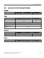
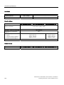
Specifications of the KTP1000 Basic and TP1500 Basic ..........................................................107
8.9
Functional Scope with WinCC flexible .......................................................................................109
Appendix................................................................................................................................................ 111
A.1
ESD guideline ............................................................................................................................111
A.2
System events............................................................................................................................113
Abbreviations......................................................................................................................................... 115
Glossary ................................................................................................................................................ 117
Index...................................................................................................................................................... 123
KTP400 Basic, KTP600 Basic, KTP1000 Basic, TP1500 Basic
Operating Instructions, 01/2009, A5E02421799-01
9
Table of contents
10
KTP400 Basic, KTP600 Basic, KTP1000 Basic, TP1500 Basic
Operating Instructions, 01/2009, A5E02421799-01
1
Overview
1.1
Product Overview
Focused on fundamentals - the new basic panels
Visualization is part of the standard repertoire for most machines these days. The cost factor
plays a crucial role in this case, especially for small machines and simple applications. HMI
devices with basic functions are often fully sufficient for simple applications .
This is exactly the demand we intend to fulfill – with our new SIMATIC Basic Panels. By
focusing on fundamentals, the HMI devices of the Basic Line offers exactly those basic
features that are demanded – and with the right economic conditions. A perfect cost-toperformance ratio.
As all devices in our product catalog, the new Basic Panels offer proven SIMATIC quality
and – regardless of their display dimensions – numerous standard software functionality, for
example, an alarm system, recipe management, trend functionality and language switching.
Users therefore profit from the advantages of visualization, such as improved process
quality, even with simple applications.
KTP400 Basic, KTP600 Basic, KTP1000 Basic, TP1500 Basic
Operating Instructions, 01/2009, A5E02421799-01
11
Overview
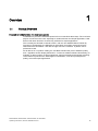
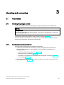
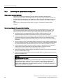
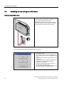
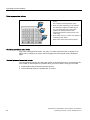
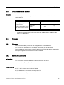
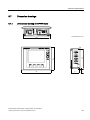
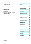
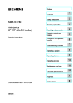
1.2 Design of the KTP400 Basic
1.2
Design of the KTP400 Basic
①
12
Recesses for mounting clamps
⑥
Connection for functional ground
②
Display / touch screen
⑦
PROFINET interface
③
Mounting seal
⑧
Power supply connector
④
Guide for labeling strips
⑨
Rating plate
⑤
Function keys
⑩
Interface name
KTP400 Basic, KTP600 Basic, KTP1000 Basic, TP1500 Basic
Operating Instructions, 01/2009, A5E02421799-01
Overview
1.3 Design of the KTP600 DP Basic
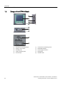
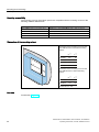
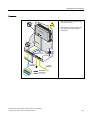
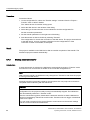
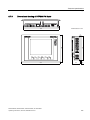
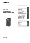
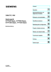
1.3
Design of the KTP600 DP Basic
①
Display / touch screen
⑦
Rating plate
②
Recesses for mounting clamps
⑧
Interface name
③
Mounting seal
⑨
DIP switch
④
Function keys
⑩
Guide for labeling strips
⑤
RS-422/485 interface
⑪
Connection for functional ground
⑥
Power supply connector
KTP400 Basic, KTP600 Basic, KTP1000 Basic, TP1500 Basic
Operating Instructions, 01/2009, A5E02421799-01
13
Overview
1.4 Design of the KTP600 PN Basic
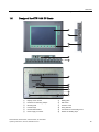
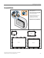
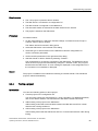
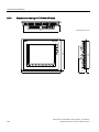
1.4
Design of the KTP600 PN Basic
14
①
Display / touch screen
⑥
Power supply connector
②
Recesses for mounting clamps
⑦
Rating plate
③
Mounting seal
⑧
Interface name
④
Function keys
⑨
Guide for labeling strips
⑤
PROFINET interface
⑩
Connection for functional ground
KTP400 Basic, KTP600 Basic, KTP1000 Basic, TP1500 Basic
Operating Instructions, 01/2009, A5E02421799-01
Overview
1.5 Design of the KTP1000 DP Basic
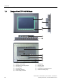
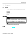
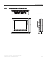
1.5
Design of the KTP1000 DP Basic
①
Display / touch screen
⑦
Rating plate
②
Recesses for mounting clamps
⑧
DIP switch
③
Mounting seal
⑨
Interface name
④
Function keys
⑩
Fixing element
⑤
RS-422/485 interface
⑪
Connection for functional ground
⑥
Power supply connector
⑫
Guides for labeling strips
KTP400 Basic, KTP600 Basic, KTP1000 Basic, TP1500 Basic
Operating Instructions, 01/2009, A5E02421799-01
15
Overview
1.6 Design of the KTP1000 PN Basic
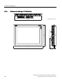
1.6
Design of the KTP1000 PN Basic
16
①
Display / touch screen
⑦
Rating plate
②
Recesses for mounting clamps
⑧
Interface name
③
Mounting seal
⑨
Fixing element
④
Function keys
⑩
Connection for functional ground
⑤
PROFINET interface
⑪
Guides for labeling strips
⑥
Power supply connector
KTP400 Basic, KTP600 Basic, KTP1000 Basic, TP1500 Basic
Operating Instructions, 01/2009, A5E02421799-01
Overview
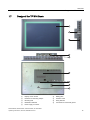
1.7 Design of the TP1500 Basic
1.7
Design of the TP1500 Basic
①
Display / touch screen
⑥
Rating plate
②
Recesses for mounting clamps
⑦
Interface name
③
Mounting seal
⑧
Fixing element
④
PROFINET interface
⑨
Connection for functional ground
⑤
Power supply connector
KTP400 Basic, KTP600 Basic, KTP1000 Basic, TP1500 Basic
Operating Instructions, 01/2009, A5E02421799-01
17
Overview
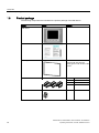
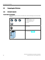
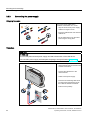
1.8 Product package
1.8
Product package
The following components are included in the product package of the HMI device.
Name
Figure
Quantity
HMI device
1
Installation instructions
1
Mounting seal
1
Enclosed with KTP 600 and
already glued in with all other HMI
devices.
Clamps with stud bolts
Mains terminal
18
5
KTP400 Basic
6
KTP600 Basic
12
KTP1000 Basic
14
TP1500 Basic
1
KTP400 Basic, KTP600 Basic, KTP1000 Basic, TP1500 Basic
Operating Instructions, 01/2009, A5E02421799-01
Overview
1.9 Accessories
1.9
Accessories
The following accessories are available for the HMI devices in the Internet at
"http://mall.automation.siemens.com" . The connector is not included in the scope of delivery
of the HMI device.
RS 422 to RS 232 converter
The converter is required for the connection of controllers of other manufacturers to Basic
Panels DP. Connect the RS 422 to RS 232 converter to the RS 422 / RS 485 interface. The
converter converts the input signals to RS-232 signals.
Order no.: 6AV6 671-8XE00-0AX0
PC/PPI cable
You need the PC/PPI cable to update the operating system with reset to factory settings.
You can also use the cable for data transfer. Connect the PC/PPI cable to the RS 422/485
port. The cable converts the input signals to RS-232 signals.
Order no.: 6ES7 901-3CB30-0XA0
Note
Set a lower bit rate if the connection is lost during the operating system update. If you use a
higher bit rate, you must use the PC/PPI cable version 3 or higher. The version code is
printed on the cable ("E stand 3," for example, corresponds to version 3).
USB/PPI cable
You need the USB/PPI cable to update the operating system with reset to factory settings.
You can also use the cable for data transfer. Connect the USB/PPI cable to the RS 422/485
port. The cable converts the input signals to USB signals.
Order no.: 6ES7 901-3DB30-0XA0
90° elbow adapter
You can use an elbow adapter at the RS 422/RS 485 interface to cope with confined spaces.
Order no.: 6AV6 671-8XD00-0XA0
PROFIBUS bus connector
We recommend using straight PROFIBUS bus connectors.
Order no.: 6GK1 500-0FC10
PROFINET RJ45 plug connector
The connection of the Basic Panels PN to PROFINET requires the RJ45 plug connector
"IE FC RJ45 Plug 2 x 2".
Order no.: 6GK1901-1BB10-2AA0
KTP400 Basic, KTP600 Basic, KTP1000 Basic, TP1500 Basic
Operating Instructions, 01/2009, A5E02421799-01
19
Overview
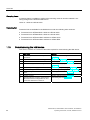
1.10 Commissioning the HMI device
Clamping frame
A clamping frame is available to reinforce the mounting cutout in case the material is not
strong enough for the KTP1000 HMI device.
Order no.: 6AV6 671-8XS00-0AX0
Protective foil
Protective foils are available for the HMI devices under the following order numbers:
● Protective foil for KTP400 Basic: 6AV6 671-2EC00-0AX0
● Protective foil for KTP600 Basic: 6AV6 671-2XC00-0AX0
● Protective foil for KTP1000 Basic: 6AV6 574-1AD00-4CX0
● Protective foil for KTP1500 Basic: 6AV6 574-1AD00-4EX0
1.10
Commissioning the HMI device
This section contains an overview of the tasks required for commissioning the HMI device.
20
Description
Section
1.
Familiarize yourself with the safety
instructions.
Safety instructions and general notes
(Page 21)
2.
Prepare the HMI device for mounting.
Preparations (Page 23)
3.
Install the HMI device.
Mounting the HMI device (Page 28)
4.
Connect the equipotential bonding.
Connecting the equipotential bonding circuit
(Page 32)
5.
Connect the power supply.
Connecting the power supply (Page 34)
6.
Connect a configuration PC.
Connecting the configuration PC (Page 36)
7.
Enable sharing for data channel on the HMI
device.
Enabling a data channel (Page 61)
8.
Transfer a project.
Starting manual transfer (Page 67)
9.
After transferring the project, disconnect the
HMI device from the configuration PC and
connect the HMI device to the PLC.
Connecting the PLC (Page 39)
KTP400 Basic, KTP600 Basic, KTP1000 Basic, TP1500 Basic
Operating Instructions, 01/2009, A5E02421799-01
Safety instructions and general notes
2.1
2
Safety instructions
Working on the control cabinet
WARNING
Open equipment
The HMI device is open equipment. That is, the HMI device may only be installed in
cubicles or cabinets which provide front panel access for operating the device.
The cubicle or cabinet in which the HMI device is installed may only be accessed with a key
or tool and only by trained, authorized personnel.
Dangerous voltage
Opening the cabinet will expose high voltage parts. Contact with these parts could be fatal.
Always disconnect the cabinet from the mains before opening it.
High frequency radiation
NOTICE
Unwanted operating states
High-frequency radiation, for example, from cellular phones, can trigger unwanted
operating states.
Installation as intended
WARNING
Installation only in machinery that conforms to the machinery directive
It is not allowed to commission the HMI device unless it has been verified that the machine
in which the HMI device is to be installed complies with Directive 98/37/EC. The following
applies as of December 29, 2009: The machine in which the HMI device is to be installed
must conform to Directive 2006/42/EC.
KTP400 Basic, KTP600 Basic, KTP1000 Basic, TP1500 Basic
Operating Instructions, 01/2009, A5E02421799-01
21
Safety instructions and general notes
2.2 Notes about usage
2.2
Notes about usage
Industrial applications
The HMI device is designed for industrial applications. It conforms to the following standards:
● Requirements of the emission standard for industrial environments, EN 61000-6-4: 2007
● ESD immunity requirements to DIN EN 61000-6-2:2005
Use in residential areas
Note
The HMI device is not intended for use in residential areas. Operation of an HMI device in
residential areas can have a negative influence on radio/TV reception.
If the HMI device is used in a residential area, you must take measures to achieve Limit
Class B conforming to EN 55011 for RF interference.
A suitable measure for achieving the RF interference level to Limit Class B includes, for
example, the use of filters in power supply lines
Individual acceptance is required.
Notes on communication
NOTICE
Communication errors caused by address conflict
Communication errors can occur if several devices in a network share the same bus
address or IP address.
Make sure that your HMI device is assigned a unique address in the network.
Note
Updating tag values following a communication error
If communication between an HMI device and PLC is interrupted, all tag values displayed on
the HMI device will be replaced by a hash mark ("#").
When the communication between the HMI device and PLC is restored, all tag values will be
updated immediately. The cycle time for updating the tag values begins again at "0."
Ethernet communication with Basic Panels PN
Basic Panels PN support the following types of communication:
• PROFINET basic function for commissioning and diagnostics
• Standard Ethernet communication
22
KTP400 Basic, KTP600 Basic, KTP1000 Basic, TP1500 Basic
Operating Instructions, 01/2009, A5E02421799-01
Mounting and connecting
3.1
Preparations
3.1.1
Checking the package contents
3
Check the package content for visible signs of transport damage and for completeness.
NOTICE
Damaged parts
Do not install parts damaged during shipment. In the case of damaged parts, contact your
Siemens representative.
The package content is described in section Product package (Page 18).
Keep the supplied documentation in a safe place. The documentation belongs to the HMI
device and is required for subsequent commissioning.
3.1.2
Checking the operating conditions
Note the following aspects before installing the HMI device:
1. Familiarize yourself with the standards, approvals, EMC parameters and technical
specifications for operation of the HMI device. This information is available in the
following chapters:
– Standards, certificates and approvals (Page 91)
– Electromagnetic compatibility (Page 92)
– Information on insulation tests, protection class and degree of protection (Page 97)
– Power supply (Page 98)
2. Check the mechanical and climatic ambient conditions for operation of the HMI device;
see Conditions of use (Page 95).
KTP400 Basic, KTP600 Basic, KTP1000 Basic, TP1500 Basic
Operating Instructions, 01/2009, A5E02421799-01
23
Mounting and connecting
3.1 Preparations
3.1.3
Selecting a mounting position
Select one of the approved mounting positions for your HMI device. The approved mounting
positions are described in the following sections.
Horizontal mounting positions
All Basic HMI devices are suitable for
horizontal mounting positions.
The following Basic HMI devices are also
suitable for vertical mounting positions:
• KTP400 Basic
• KTP600 Basic
Vertical mounting positions
The Basic HMI devices are self-ventilating.
Vertical and angled mounting is permitted in:
• Mounting cabinets
• Control cabinets
• Switchboards
• Consoles
50 °C
0 °C
rದr
rದr
40 °C
0 °C
40 °C
0 °C
CAUTION
Exceeding the ambient temperature
Forced ventilation is required if the maximum permitted ambient temperature for operating
the HMI device is exceeded. The HMI device can otherwise be damaged and its approvals
and warranty will be void.
See also
Conditions of use (Page 95)
24
KTP400 Basic, KTP600 Basic, KTP1000 Basic, TP1500 Basic
Operating Instructions, 01/2009, A5E02421799-01
Mounting and connecting
3.1 Preparations
3.1.4
Checking clearances
The following clearances are required around the HMI device to ensure sufficient selfventilation:
All Basic
Panels
x
y
y
KTP400
KTP600
All dimensions in mm
x
z
z
x
x
y
y
3.1.5
Required clearance around the HMI
devices.
x
y
z
.73
.73
.73 73
Making the mounting cut-out
NOTICE
Stability of the mounting cut-out
The material in the area of the mounting cut-out must provide sufficient strength to
guarantee the enduring and safe mounting of the HMI device.
The force of the clamps or operation of the device may not lead to deformation of the
material in order to achieve the degrees of protection described below.
Degrees of protection
The degrees of protection of the HMI device can only be guaranteed if the following
requirements are met:
● Material thickness at the mounting cut-out for IP65 degree of protection, or for
enclosure type 4X/type 12 (indoor use only): 2 mm to 6 mm
● Permitted deviation from plane at the mounting cut-out: ≤ 0.5 mm
This condition must be fulfilled for the mounted HMI device.
● Permissible surface roughness in the area of the seal: ≤ 120 µm (Rz 120)
A clamping frame is additionally available for mounting the KTP1000 Basic to panels with a
material thickness < 2 mm at the mounting cut-out. The frame enables you to achieve IP65
degree of protection or the protection class for enclosures type 4X/type 12.
KTP400 Basic, KTP600 Basic, KTP1000 Basic, TP1500 Basic
Operating Instructions, 01/2009, A5E02421799-01
25
Mounting and connecting
3.1 Preparations
Mounting compatibility
The mounting cut-outs of the Basic panels are compatible with the mounting cut-outs of the
following SIMATIC HMI devices:
Mounting cut-out for the Basic Panel
Compatible to the mounting cut-outs of the HMI device
KTP400
TP 177B 4"
KTP600
TP 177 A, TP 177B 6", TP 177micro
KTP1000
MP 277 10" Touch, MP 377 12" Touch
TP1500
MP 377 15" Touch, Thin Client 15" Touch
Dimensions of the mounting cut-out
Dimensions of the mounting cut-out for the
Basic HMI devices in horizontal mounting
position:
w
w
h
+1
0
h
+1
0
.73
.73
.73
73
Dimensions of the mounting cut-out for the
Basic HMI devices in vertical mounting
position:
+1
0
h
.73
.73
w
+1
0
All dimensions in mm
See also
Accessories (Page 19)
26
KTP400 Basic, KTP600 Basic, KTP1000 Basic, TP1500 Basic
Operating Instructions, 01/2009, A5E02421799-01
Mounting and connecting
3.1 Preparations
3.1.6
Labeling the function keys
Note
Do not write on the keyboard to label the function keys.
Any printable and writable foil can be used as labeling strip. The permitted thickness of the
labeling strip is 0.15 mm. Paper labeling strips are inappropriate.
1
PLQ
6
.7
3
1. Edit the template on the PC. The
template is available in the
CD_3\Documents\<language>\Slid
es directory on the WinCC flexible
DVD.
2. Print the edited template on foil.
3. Apply a fixing spray film to the
labeling strips.
4. Wait approx. 5 minutes until the
fixing spray is dry and smearproof.
5. Cut out the labeling strip.
6. Cut off the corners of the labeling
strips at an angle of 45° to make it
easier to insert them.
7. Slide the labeling strips into the
slot up to the end of the guide.
The labeling strips will protrude
approximately 3 cm out of the
guide. The template dimensions
for the labeling strips are designed
so that the labeling is correctly
placed for the function keys. It is
not necessary to secure the
labeling strip.
7
KTP400 Basic, KTP600 Basic, KTP1000 Basic, TP1500 Basic
Operating Instructions, 01/2009, A5E02421799-01
27
Mounting and connecting
3.2 Mounting the HMI device
3.2
Mounting the HMI device
Required tools and accessories
Before beginning mounting, have the following tools and accessories at hand:
Slotted screwdriver, size 2
Mounting clamps
• KTP400 Basic: 5
• KTP600 Basic: 6
• KTP1000 Basic: 12
• TP1500 Basic: 14
Inserting the HMI device
,3
1. If necessary, insert the mounting
seal in the groove on the back of
the HMI device front panel.
Ensure that the mounting seal is not
twisted. A correctly inserted
mounting seal is required to ensure
IP65 degree of protection.
2. Insert the HMI device into the
mounting cut-out from the front.
Ensure that the protruding labeling
strips are not caught between the
mounting cut-out and HMI device.
28
KTP400 Basic, KTP600 Basic, KTP1000 Basic, TP1500 Basic
Operating Instructions, 01/2009, A5E02421799-01
Mounting and connecting
3.2 Mounting the HMI device
Securing the HMI device
1. Insert the first clamp at the first
position of the recesses on the back
of the HMI device.
Set the clamp positions for your HMI
device to match those of the figures
in the following table row.
ื 0.2
Nm
2. Secure the clamps using a size 2
screwdriver. The maximum
permitted torque is 0.2 N/m.
3. Repeat steps 1 and 2 for all clamps
required to secure your HMI device.
.7
3
ದ
ದ
ದ
ದ
ದ
ದ
.73
.73
ದ
ದ
ದ
ದ
ದ
ದ
ದ
ದ
ದ
ದ
ದ
73
ದ
ದ
KTP400 Basic, KTP600 Basic, KTP1000 Basic, TP1500 Basic
Operating Instructions, 01/2009, A5E02421799-01
.73
ದ
29
Mounting and connecting
3.3 Connecting the HMI device
3.3
Connecting the HMI device
3.3.1
Connection sequence
Required tools and accessories
Before beginning the connection of the HMI device, have the following tools and accessories
at hand:
Screwdriver:
• Slotted screwdriver, size 2
• Philips screwdriver, size 3
• Torx screwdriver size 3
Crimp pliers
Mains terminal
24 VDC with sufficient amperage.
See Specifications (Page 105)
30
KTP400 Basic, KTP600 Basic, KTP1000 Basic, TP1500 Basic
Operating Instructions, 01/2009, A5E02421799-01
Mounting and connecting
3.3 Connecting the HMI device
Procedure
Keep to the following sequence of tasks when connecting the HMI device:
1. Connecting the equipotential bonding circuit (Page 32)
2. Connecting the power supply (Page 34)
3. Connecting the configuration PC (Page 36)
4. Connecting the PLC (Page 39)
NOTICE
Strain relief
Contacts can be broken or wires can be torn off if cables are not provided adequate
strain relief.
Provide adequate strain relief for all cables.
See also
Securing the cables (Page 43)
KTP400 Basic, KTP600 Basic, KTP1000 Basic, TP1500 Basic
Operating Instructions, 01/2009, A5E02421799-01
31
Mounting and connecting
3.3 Connecting the HMI device
3.3.2
Connecting the equipotential bonding circuit
Differences in electrical potential
Differences in electrical potential can develop between spatially separated plant
components. Such electrical potential differences can lead to high equalizing currents over
the data cables and therefore to the destruction of their interfaces. Equalizing currents can
develop if the cable shielding is terminated at both ends and grounded to different plant
parts.
Differences in potential may develop when a system is connected to different mains
supplies.
General requirements for equipotential bonding
Differences in potential must be reduced by means of equipotential bonding in order to
ensure trouble-free operation of the relevant components of the electronic system. The
following must therefore be observed when installing the equipotential bonding circuit:
● The effectiveness of equipotential bonding increases as the impedance of the
equipotential bonding conductor decreases or as its cross-section increases.
● If two plant parts are interconnected by means of shielded data cables and their shielding
is bonded at both ends to the grounding/protective conductor, the impedance of the
additionally installed equipotential bonding cable must not exceed 10% of the shielding
impedance.
● The cross-section of an equipotential bonding conductor must be capable of handling the
maximum equalizing current. The best practical results for equipotential bonding between
two cabinets have been achieved with a minimum conductor cross-section of 16 mm².
● Use equipotential bonding conductors made of copper or galvanized steel. Establish a
large surface contact between the equipotential bonding conductors and the
grounding/protective conductor and protect these from corrosion.
● Clamp the shielding of the data cable on the HMI device flush and near the equipotential
rail using suitable cable clamps.
● Route the equipotential bonding conductor and data cables in parallel and with minimum
clearance between these.
NOTICE
Equipotential bonding cable
Cable shielding is not suitable for equipotential bonding. Always use the prescribed
equipotential bonding conductors. The cross-section of the equipotential bonding
conductor must not be less than 16 mm². Always use cables with an adequate crosssection when installing MPI and PROFIBUS DP networks. The interface modules may
otherwise be damaged or destroyed.
32
KTP400 Basic, KTP600 Basic, KTP1000 Basic, TP1500 Basic
Operating Instructions, 01/2009, A5E02421799-01
Mounting and connecting
3.3 Connecting the HMI device
Procedure
1. Interconnect functional ground of the
HMI device with an grounding cable,
cross-section 4 mm2.
1
.7
3
2. Connect the grounding cable of the
HMI device to the equipotential
bonding rail.
PPt
2
ุPPt
ุPPt
352),%86
352),1(7
KTP400 Basic, KTP600 Basic, KTP1000 Basic, TP1500 Basic
Operating Instructions, 01/2009, A5E02421799-01
33
Mounting and connecting
3.3 Connecting the HMI device
3.3.3
Connecting the power supply
Stripping the cable
1
m
6m
Use power supply cables with a
maximum cross-section of 1.5 mm2.
1. Strip the ends of both power supply
cables to a length of 6 mm.
2
2. Insert the cable sleeve onto the bare
cable ends.
3. Fix the cable sleeve onto the cable
ends using the crimp pliers.
3
Procedure
CAUTION
24 VDC only
An incorrectly dimensioned power supply can lead to destruction of the HMI device.
Use a 24 VDC power supply with adequate amperage; see Specifications (Page 105).
1. Insert the two power cables into the
mains terminal and secure them with
a slotted screwdriver.
2. Connect the HMI device to the
mains terminal.
.7
3
3. Switch off the power supply.
4. Insert the two remaining cable ends
into the power terminal and secure
them with the slotted screwdriver.
2
Ensure correct polarity.
1
3
M
4
L+
34
KTP400 Basic, KTP600 Basic, KTP1000 Basic, TP1500 Basic
Operating Instructions, 01/2009, A5E02421799-01
Mounting and connecting
3.3 Connecting the HMI device
3.3.4
Connecting a programming device
A programming device provides the following options:
● Transferring projects.
● Transferring device images.
Connecting a programming device to a Basic Panel DP
Note
A programming device cannot be used to reset the HMI device to factory settings.
1. Shut down the HMI device. Verify
that the DIP switch on the rear panel
of the HMI device is in the following
position:
21
RS 422/ 485
2. Connect an RS 485 PROFIBUS
connector to the HMI device.
PROFIBUS
3. Connect an RS 485 PROFIBUS
connector to the programming
device.
RS 485
PG
KTP400 Basic, KTP600 Basic, KTP1000 Basic, TP1500 Basic
Operating Instructions, 01/2009, A5E02421799-01
35
Mounting and connecting
3.3 Connecting the HMI device
3.3.5
Connecting the configuration PC
A configuration PC provides the following options:
● Transferring projects.
● Transferring device images.
● Resetting HMI device to factory settings.
Connecting a configuration PC to a Basic Panel DP
1. Shut down the HMI device.
2. Connect the RS 485 connector of
the PC/PPI cable to the HMI device.
RS422/485
3. Connect the RS 232 connector of
the PC/PPI cable to the
configuration PC.
You can also use the USB/PPI cable
from the accessories instead of the
PC/PPI cable.
Serial
You can find ordering information in the
Accessories (Page 19) section.
RS 232
PC
36
KTP400 Basic, KTP600 Basic, KTP1000 Basic, TP1500 Basic
Operating Instructions, 01/2009, A5E02421799-01
Mounting and connecting
3.3 Connecting the HMI device
Configuring the PC/PPI cable
Configure the transmission speed using the DIP switches of the PC/PPI cable if using the
PC/PPI cable to interconnect the HMI device with the configuration PC.
Note
Set a lower bit rate if the connection is lost during the operating system update. If you use a
higher bit rate, you must use the PC/PPI cable release 3 or higher. The version code is
printed on the cable ("E stand 3," for example, corresponds to version 3).
Set the DIP switches 1 to 3 to the
same value as in WinCC flexible.
DIP switches 4 to 8 must be set to
"0". In the figure, the bit rate is set to
115.2 kbps.
You can set the following bit rates:
DIP switch 1
DIP switch 2
DIP switch 3
115,2
Bit rate in kbps
1
1
0
57,6
1
1
1
38,4
0
0
0
19,2
0
0
1
9,6
0
1
0
4,8
0
1
1
2,4
1
0
0
1,2
1
0
1
KTP400 Basic, KTP600 Basic, KTP1000 Basic, TP1500 Basic
Operating Instructions, 01/2009, A5E02421799-01
37
Mounting and connecting
3.3 Connecting the HMI device
Connecting a configuration PC to a Basic Panel PN
CAUTION
Data network security for communication via Ethernet
End users are themselves responsible for ensuring security of their data network in
Ethernet-based communication, such as PROFINET, HTTP, Sm@rtAccess, Sm@rtService
and OPC, since operation of the device cannot be guaranteed if the device is subject to
targeted attacks resulting in overload, for example.
NOTICE
RJ45 plug connector with 180° output required
The connection of the Basic Panels PN to the HMI device requires the RJ45 plug connector
"IE FC RJ45 Plug 2 x 2". You can find ordering information in the Accessories (Page 19)
section.
1. Shut down the HMI device.
2. Connect one RJ45 connector of the LAN
cable to the HMI device.
PROFINET (LAN)
3. Connect the other RJ45 connector of the
LAN cable to the configuration PC.
LAN
LAN
PC
See also
Data transmission options (Page 67)
38
KTP400 Basic, KTP600 Basic, KTP1000 Basic, TP1500 Basic
Operating Instructions, 01/2009, A5E02421799-01
Mounting and connecting
3.3 Connecting the HMI device
3.3.6
Connecting the PLC
Connect the HMI device to the PLC if it contains an operating system and an executable
project.
Connecting a PLC to a Basic Panel DP
You can interconnect Basic Panels
DP via RS 422/485 port with the
following SIMATIC PLCs:
• SIMATIC S7-200
• SIMATIC S7-300/400
RS 422/485
PROFIBUS
DP
SIMATIC S7-200
SIMATIC S7-300/400
KTP400 Basic, KTP600 Basic, KTP1000 Basic, TP1500 Basic
Operating Instructions, 01/2009, A5E02421799-01
RS 422/485
Serial
RS 232
You can interconnect Basic Panels
DP with the following PLCs via
converter (from the accessories):
• Modicon Modbus
• Allen Bradley DF1
For ordering information for the
converters, refer to chapter
Accessories (Page 19).
If using the RS 422/485 port, read the
notes on configuration in the following
section.
Third party PLC
39
Mounting and connecting
3.3 Connecting the HMI device
Configuring the RS-422/485 interface
The DIP switch for configuring the RS-422/485 interface is installed on the rear panel of the
HMI device.
The DIP switch is set at the factory to enable communication with the SIMATIC PLC via
RS 485.
Note
Note the diagrams of DIP switch settings on the rear panel of the HMI device.
The following table shows the DIP switch settings. The send and receive direction is toggled
internally using the RTS signal.
Communication
Switch setting
DP/MPI/PPI
21
Meaning
No RTS signal on connector, for data exchange between
the SIMATIC PLC and the HMI device
(factory state)
RTS signal on pin 4, same as PLC,
for example, for commissioning
21
RTS signal on pin 9, same as for a programming device,
for example, for commissioning
21
RS 422/485
RS-422/485 interface is active, for example, for
connecting PLCs of other manufacturers
21
40
KTP400 Basic, KTP600 Basic, KTP1000 Basic, TP1500 Basic
Operating Instructions, 01/2009, A5E02421799-01
Mounting and connecting
3.3 Connecting the HMI device
Connecting the PLC to a Basic Panel PN
CAUTION
Data network security for communication via Ethernet
End users are themselves responsible for ensuring security of their data network in
Ethernet-based communication, such as PROFINET, HTTP, Sm@rtAccess, Sm@rtService
and OPC, since operation of the device cannot be guaranteed if the device is subject to
targeted attacks resulting in overload, for example.
NOTICE
RJ45 plug connector with 180° output required
The connection of the Basic Panels PN to the HMI device requires the RJ45 plug connector
"IE FC RJ45 Plug 2 x 2". You can find ordering information in the Accessories (Page 19)
section.
Basic Panels PN can be connected to
the following SIMATIC PLCs:
• SIMATIC S7-200
• SIMATIC S7-300/400
• SIMATIC S7 with PROFINET
interface
PROFINET (LAN)
The connection is set up via
PROFINET/LAN.
PROFINET
PROFINET
LAN
SIMATIC S7-200
SIMATIC S7-300/400
See also
Connecting the equipotential bonding circuit (Page 32)
KTP400 Basic, KTP600 Basic, KTP1000 Basic, TP1500 Basic
Operating Instructions, 01/2009, A5E02421799-01
41
Mounting and connecting
3.4 Switching on and testing the HMI device
3.4
Switching on and testing the HMI device
Switching on the HMI device.
Switching on the power supply.
The screen lights up after power is switched on. A
progress bar is displayed during startup.
If the HMI device fails to start, you have probably
crossed the wires on the mains terminal. Check the
connected wires and change their connection.
.7
3
M
L+
The Loader opens after the operating system has started.
•
•
•
42
Press the "Transfer" button to set the HMI device
to "Transfer" mode.
The transfer mode can only be activated when at
least one data channel has been enabled for the
transfer.
Press the "Start" button to start the project on the
HMI device.
If you do not perform an operation, the project on
the HMI device is started automatically on
expiration of a delay time.
Press the "Control Panel" button to open the
Control Panel of the HMI device.
You can make a variety of settings in the Control
Panel, for example, the transfer settings.
KTP400 Basic, KTP600 Basic, KTP1000 Basic, TP1500 Basic
Operating Instructions, 01/2009, A5E02421799-01
Mounting and connecting
3.5 Securing the cables
Shutting down the HMI Device
1. Close any active projects on the HMI device.
2. Shut down the HMI device. You have the following shutdown options:
– Switch off the power supply.
– Remove the mains terminal from the HMI device.
3.5
Securing the cables
The following HMI devices come equipped with a fixing element on the back for strain relief:
● KTP1000 Basic DP
● KTP1000 Basic PN
● TP1500 Basic
After the power-on test, to ensure strain relief, use cable ties to secure the connected cables
to the marked fixing element.
)L[LQJHOHPHQW
KTP400 Basic, KTP600 Basic, KTP1000 Basic, TP1500 Basic
Operating Instructions, 01/2009, A5E02421799-01
43
Mounting and connecting
3.5 Securing the cables
44
KTP400 Basic, KTP600 Basic, KTP1000 Basic, TP1500 Basic
Operating Instructions, 01/2009, A5E02421799-01
Operating the user interface
4.1
4
Overview
All Basic HMI devices feature a touch screen. Certain Basic HMI devices feature function
keys. Use the touch screen and function keys to operate the Control Panel or the project
running on your HMI device.
DANGER
Incorrect operation
A project can contain certain operations that require in-depth knowledge about the specific
plant on the part of the operator.
Ensure that only trained professional personnel operate the plant.
Operating the touch screen
CAUTION
Damage to the touch screen
Pointed or sharp objects can damage the plastic surface of the touch screen.
Always operate the touch screen with your fingers or with a touch pen only.
Triggering unintended actions
Touching several operator controls at the same time can trigger unintended actions.
Touch only one operator control on the screen at a time.
Operator controls are touch-sensitive symbols on the screen of the HMI device.
They are basically operated in the same way as mechanical keys. You activate operator
controls by touching them with your finger.
Note
The HMI device returns a visual feedback as soon as it detects that an operator control has
been touched.
The visual feedback is independent of any communication with the PLC. The visual feedback
signal therefore does not indicate whether or not the relevant action is actually executed.
KTP400 Basic, KTP600 Basic, KTP1000 Basic, TP1500 Basic
Operating Instructions, 01/2009, A5E02421799-01
45
Operating the user interface
4.1 Overview
Examples of operator controls:
● Buttons
Buttons can assume the following states:
"Untouched"
"Touched"
● Invisible buttons
The focus of invisible buttons is by default not indicated following selection. No optical
operation feedback is provided in this case.
The configuration engineer may, however, configure invisible buttons so that their outline
appears as lines when touched. This outline remains visible until you select another
operator control.
● I/O fields
A screen keyboard appears as visual feedback after you touched an I/O field, for
example, to enter a password.
Depending on the HMI device and the configured operator control, the system displays
different screen keyboards for entering numerical or alphanumerical values.
The screen keyboard is automatically hidden again when input is complete.
Note
Description of all operator controls
A comprehensive description of all operator controls for your HMI device is provided in
the WinCC flexible Online Help in the section "System alarms".
Operating function keys
The function keys can be assigned global or local functions:
● Function keys with global function assignment
A function key with global function assignment always triggers the same action on the
HMI device or in the PLC, regardless of the currently displayed screen. An example of
such an action is the activation of a screen, or the closing an alarm window.
● Function keys with local function assignment
A function key with local function assignment is screen-specific and is therefore only
effective within the active screen.
The function assigned to a function key can vary from screen to screen.
The function key could be assigned only a single function within a screen only, that is, either
a global or a local function. Local function assignments override global function assignments.
46
KTP400 Basic, KTP600 Basic, KTP1000 Basic, TP1500 Basic
Operating Instructions, 01/2009, A5E02421799-01
Operating the user interface
4.2 General functions of the screen keyboard
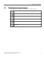
4.2
General functions of the screen keyboard
The following keys are available on the screen keyboard of all Basic HMI devices:
Cursor left
Cursor right
Delete character
Cancel input
Confirm input
Display infotext. This key only appears when an infotext has been configured for the
operator control.
KTP400 Basic, KTP600 Basic, KTP1000 Basic, TP1500 Basic
Operating Instructions, 01/2009, A5E02421799-01
47
Operating the user interface
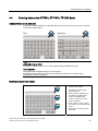
4.3 Entering data on the KTP400 Basic
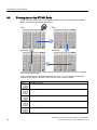
4.3
Entering data on the KTP400 Basic
Due to the small display, the screen keyboard and the input concept of the KTP400 Basic
differs compared to other Basic HMI devices.
7H[W
7H[W
681
6\PEROV
1XPEHUV
681
681
The screen keyboard appears on the HMI device touch screen when you touch an operator
control that requires input.
The screen keyboard of the KTP400 features four views. You can change the view while
making entries using the buttons in the fourth row of the screen keyboard:
Button
Changes to the view
Entering text, characters "A" to "M"
Entering text, characters "N" to "Z"
Entering numbers, "0" to "9," signed or unsigned and with or without decimal places
Entering special characters
Entering text, shift to lower case letters
48
KTP400 Basic, KTP600 Basic, KTP1000 Basic, TP1500 Basic
Operating Instructions, 01/2009, A5E02421799-01
Operating the user interface
4.3 Entering data on the KTP400 Basic
Note
Job mailbox has no effect
PLC job 51 "Select screen" has no effect while the screen keyboard is open.
Key assignment
The alphanumerical keyboard layout is monolingual.
A language change within the project does not have any effect on the layout of the
alphanumerical screen keyboard.
Entering alphanumerical values
1. Touch the desired operator control on the
screen.
1
The alphanumerical screen keyboard opens.
2. Enter the value. Depending on the settings,
the HMI device outputs an audible signal.
You can change the view of the screen
keyboard using the keys <N-Z> and <A-M>.
Use the <Shift> key to enter lower-case
letters.
3. Press <Return> key to confirm your entries, or
cancel them with <ESC>.
Either action closes the screen keyboard.
2
3
KTP400 Basic, KTP600 Basic, KTP1000 Basic, TP1500 Basic
Operating Instructions, 01/2009, A5E02421799-01
49
Operating the user interface
4.3 Entering data on the KTP400 Basic
Entering numerical values
1. Touch the desired operator control on the
screen.
1
The numerical screen keyboard opens.
2. Enter the value. Depending on the settings,
the HMI device outputs an audible signal.
2
3
You can change the view of the screen
keyboard for entering numbers with
hexadecimal notation using the <N-Z> and
<A-M> keys.
3. Press <Return> key to confirm your entries, or
cancel them with <ESC>.
Either action closes the screen keyboard.
Checking numerical value limits
Tags can be assigned limit values. Any entry of a value outside this limit is rejected. If an
alarm view is configured, a system event is triggered and the original value is displayed
again.
Decimal places of numerical values
The configuration engineer can define the number of decimal places for a numerical text box.
The number of decimal places is checked when you enter a value in this type of I/O field.
● Decimal places that exceed the limit are ignored.
● Unused decimal places are padded with "0" entries.
50
KTP400 Basic, KTP600 Basic, KTP1000 Basic, TP1500 Basic
Operating Instructions, 01/2009, A5E02421799-01
Operating the user interface
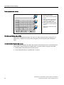
4.4 Entering data on the KTP600, KTP1000, TP1500 Basic
4.4
Entering data on the KTP600, KTP1000, TP1500 Basic
Alphanumerical screen keyboard
The screen keyboard appears on the HMI device touch screen when you touch an operator
control that requires input.
7H[W
1XPEHUV
681
))))
Note
Job mailbox has no effect
PLC job 51 "Select screen" has no effect while the screen keyboard is open.
Key assignment
The alphanumerical keyboard layout is monolingual.
A language change within the project does not have any effect on the layout of the
alphanumerical screen keyboard.
Entering alphanumerical values
1
2
3
1. Touch the desired operator
control on the screen.
The alphanumerical screen
keyboard opens.
2. Enter the value. Depending on
the settings, the HMI device
outputs an audible signal.
Use the <Shift> key to enter
lower-case letters.
3. Press <Return> key to confirm
your entries, or cancel them with
<ESC>.
Either action closes the screen
keyboard.
KTP400 Basic, KTP600 Basic, KTP1000 Basic, TP1500 Basic
Operating Instructions, 01/2009, A5E02421799-01
51
Operating the user interface
4.4 Entering data on the KTP600, KTP1000, TP1500 Basic
Entering numerical values
1
1. Touch the desired operator
control on the screen.
2
The numerical screen keyboard
opens.
2. Enter the value. Depending on
the settings, the HMI device
outputs an audible signal.
3. Press <Return> key to confirm
your entries, or cancel them with
<ESC>.
3
Either action closes the screen
keyboard.
Checking numerical value limits
Tags can be assigned limit values. Any entry of a value outside this limit is rejected. If an
alarm view is configured, a system event is triggered and the original value is displayed
again.
Decimal places of numerical values
The configuration engineer can define the number of decimal places for a numerical text box.
The number of decimal places is checked when you enter a value in this type of I/O field.
● Decimal places that exceed the limit are ignored.
● Unused decimal places are padded with "0" entries.
52
KTP400 Basic, KTP600 Basic, KTP1000 Basic, TP1500 Basic
Operating Instructions, 01/2009, A5E02421799-01
5
Configuring the operating system
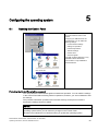
5.1
Opening the Control Panel
Open the Control Panel by pressing
the "Control Panel" button of the
Loader.
%DVLF3DQHOV'3
Configure your HMI device in the
Control Panel. You can make the
following settings:
• Communication settings
• Settings for operation
• Password protection
• Transfer settings
• Screen saver
• Acoustic signals
The "MPI / Profibus Settings" is only
available on Basic Panels DP.
The "Profinet" is only available on
Basic Panels PN.
%DVLF3DQHOV31
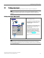
Protecting the Control Panel with a password
You can protect the Control Panel against unauthorized operation. You can read the settings
in the Control Panel without having entered a password, however, you are not allowed to edit
the settings.
This prevents inadvertent operations and increases security for the plant or machine
because the settings cannot be edited.
NOTICE
If the password is no longer available for the Control Panel, you first have to update the
operating system before you can make any changes in the Control Panel.
All data on the HMI device is overwritten when you update the operating system!
KTP400 Basic, KTP600 Basic, KTP1000 Basic, TP1500 Basic
Operating Instructions, 01/2009, A5E02421799-01
53
Configuring the operating system
5.2 Overview
5.2
Overview
The following table shows the functions available in the Control Panel for configuring your
HMI device.
Symbol
Function
Changing MPI/DP settings (Page 55)
Changing the network configuration (Page 56)
Changing monitor settings (Page 57)
Displaying information about the HMI device (Page 58)
Calibrating the touch screen (Page 59)
Displaying licensing information for the HMI device (Page 60)
Changing password settings (Page 63)
Enabling a data channel (Page 61)
Setting the Screen Saver (Page 64)
Setting acoustic signals (Page 64)
54
KTP400 Basic, KTP600 Basic, KTP1000 Basic, TP1500 Basic
Operating Instructions, 01/2009, A5E02421799-01
Configuring the operating system
5.3 Changing MPI/DP settings
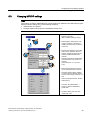
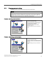
5.3
Changing MPI/DP settings
Note
The settings for MPI or PROFIBUS DP communication are defined in the HMI device project.
Edit the transfer settings only in the following situations:
• Initial transfer of a project.
• Changes made to the project are activated at a later time.
1. Press the "MPI / Profibus Settings"
button to open the
"MPI / Profibus Settings" dialog.
2. Deactivate the "Panel is the only
master on the bus" check box if
additional masters are connected
to the bus.
5
3. Enter the bus address for the HMI
device in the "Address" text box.
The bus address must be unique
within the MPI/PROFIBUS DP
network.
2
3
4
Enter the time limit for PROFIBUS
communication in the "Time-out"
text box.
Valid values are 1 s, 10 s and
100 s.
4. Select the transmission rate from
the "Transmission Rate" text box.
Enter the highest station address
on the bus in the "Highest Station"
text box. Valid range of values: 1 to
126.
Select the profile from the "Profile"
selection box.
Press the "Bus Parameters..."
button to view the PROFIBUS
profile data.
5. Close the dialog and save your
entries with "OK".
KTP400 Basic, KTP600 Basic, KTP1000 Basic, TP1500 Basic
Operating Instructions, 01/2009, A5E02421799-01
55
Configuring the operating system
5.4 Changing the network configuration
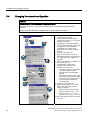
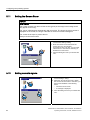
5.4
Changing the network configuration
NOTICE
Communication errors caused by IP address conflicts
Communication errors can occur if several devices in a network share the same IP
address.
Assign each HMI device an IP address that is unique within the network.
10
2
3
4
5
6
7
8
9
56
1. Press the "Profinet" button to open the
"Profinet Settings" dialog.
2. Choose either automatic address
assignment via DHCP, or user-specific
address assignment.
3. If assigning a user-specific address,
use the screen keyboard to enter valid
IP addresses in the "IP Address",
"Subnet Mask" text boxes and if
applicable in the "Default Gateway"
text box.
4. Change to the "Mode" tab.
5. Enter the transmission rate for the
PROFINET network in the "Speed" text
box. Valid values are 10 Mbps and
100 Mbps.
6. Select "Half duplex" or "Full duplex" as
the connection mode.
7. The following functions will be
activated if the checkbox "Auto
Negotiation" has been set:
– Connection mode and transmission
rate will be detected and set
automatically in the PROFINET
network.
– The "Auto-Crossover" function will
be activated, which means the HMI
device can be connected to a PC or
a controller without additional
crossover cable.
8. Change to the "Device" tab.
9. Enter a network name for your HMI
device. The name must meet the
following conditions.
– Maximum length: 240 characters
– Special characters: only "-" and "."
– Invalid syntax: "n.n.n.n" (n=0 to
999) and "port-yxz" (x, y, z =0 to 9)
10. Close the dialog and save your entries
with "OK".
KTP400 Basic, KTP600 Basic, KTP1000 Basic, TP1500 Basic
Operating Instructions, 01/2009, A5E02421799-01
Configuring the operating system
5.5 Changing monitor settings
5.5
Changing monitor settings
NOTICE
Orientation of the screen for KTP400 Basic and KTP600 Basic
The screen orientation is defined by the configuration engineer in the course of project
creation. The appropriate screen orientation is set automatically when you transfer the
project to the HMI device.
Do not make any changes to the screen orientation if a project exists on the HMI device.
The screen content may otherwise be truncated.
1. Press the "OP" button to open the
"OP Properties" dialog.
2. Basic Panels color:
5
Press the "UP" and "DOWN" buttons to adjust
the screen brightness.
Basic Panels mono:
Press the "UP" and "DOWN" buttons to adjust
the screen contrast.
3. Only for KTP400 and KTP600:
3
KTP400
KTP600
Select the screen orientation:
– "Landscape" for landscape
– "Portrait" for portrait
4. Set the delay time in the "Delay time" text
box. The delay time in seconds defines the
waiting time expiring between the appearance
of the loader and the start of the project.
4
Valid range of values: 0 s to 60 s.
5. Close the dialog and save your entries with
"OK".
Note
Immediate start of the project with a delay time of 0 seconds
The project starts immediately if a delay time of 0 seconds is set. It is then no longer possible
to call the Loader after switching on the HMI device. To handle this situation, you need to
configure an operator control with the "Close project" function.
KTP400 Basic, KTP600 Basic, KTP1000 Basic, TP1500 Basic
Operating Instructions, 01/2009, A5E02421799-01
57
Configuring the operating system
5.6 Displaying information about the HMI device
5.6
Displaying information about the HMI device
1. Press the "OP" button to open the
"OP Properties" dialog.
2. Change to the "Device" tab.
The "License" tab is used to display specific
information on the HMI device. You will need
this information when contacting Technical
Support.
– "Device:" HMI device name
– "Flashsize": Size of internal flash memory
to which the HMI device image and project
data are saved. The size of internal flash
memory is not equivalent to application
memory available for a project.
– "Bootloader": Boot loader version
– "Bootl. Rel. Date": Release date of the
boot loader
– "Image": Version of the HMI device image
3. Close the dialog with "OK".
58
KTP400 Basic, KTP600 Basic, KTP1000 Basic, TP1500 Basic
Operating Instructions, 01/2009, A5E02421799-01
Configuring the operating system
5.7 Calibrating the touch screen
5.7
Calibrating the touch screen
1. Press the "OP" button to open the
"OP Properties" dialog.
2. Change to the "Touch" tab.
10
3. Press the "Recalibrate" button to
open the calibration screen.
4. Touch the cross in the screen center
using the touch pen or your finger.
5.
6.
7.
8.
Use the touch pen
or your finger to touch the
crosshair handles in the corners
of the screen.
9. Touch the cross in the screen center
once again using the touch pen or
your finger to confirm your entries.
10. Close the dialog and save your
entries with "OK".
5
8
&DUHIXOO\SUHVVDQGEULHIO\KROGVW\OXVRQWKHFHQWHURI
WKHWDUJHW5HSHDWDVWKHWDUJHWPRYHVDURXQGWKHVFUHHQ
6
7
New calibration settings have been measured.
Tap the screen to register saved data.
Wait for 30 seconds to cancel saved data and
keep the current setting.
9
Time limit: 30 sec
KTP400 Basic, KTP600 Basic, KTP1000 Basic, TP1500 Basic
Operating Instructions, 01/2009, A5E02421799-01
59
Configuring the operating system
5.8 Displaying licensing information for the HMI device
5.8
Displaying licensing information for the HMI device
1. Use the "OP" button to open the
"OP Properties" dialog.
2. Open the "License" tab.
The "License" tab is used to display the
licensing information for the software of the
HMI device.
3. Close the dialog with "OK."
60
KTP400 Basic, KTP600 Basic, KTP1000 Basic, TP1500 Basic
Operating Instructions, 01/2009, A5E02421799-01
Configuring the operating system
5.9 Enabling a data channel
5.9
Enabling a data channel
You must enable at least one data channel to transfer a project to the HMI device.
Note
After having completed the project transfer, you can protect the HMI device against
unintentional overwriting of project data and of the HMI device image by locking all data
channels.
Enabling a data channel - Basic Panels DP
1. Press the "Transfer" button to open the
"Transfer Settings" dialog.
3
2
2
2. If the HMI device is interconnected with the
configuration PC via PC-PPI cable, activate
the "Enable Channel" check box in the
"Channel 1" field.
If the HMI device is interconnected with a
programming device via PROFIBUS, activate
the "Enable Channel" check box in the
"Channel 2" field.
Press the "Advanced" button to open the
"MPI / Profibus Settings" dialog. Verify the
PROFIBUS parameters in this dialog. A
description of the "MPI / Profibus Settings"
dialog is provided in chapter 5.3, Changing
MPI/DP settings (Page 55).
3. Close the dialog and save your entries with
"OK".
Note
Automatic transfer is activated be setting the "Remote Control" check box. If automatic
transfer is activated, the HMI device can be set remotely to transfer mode by a configuration
PC or programming device.
KTP400 Basic, KTP600 Basic, KTP1000 Basic, TP1500 Basic
Operating Instructions, 01/2009, A5E02421799-01
61
Configuring the operating system
5.9 Enabling a data channel
Enabling a data channel - Basic Panels PN
1. Press the "Transfer" button to open the
"Transfer Settings" dialog.
2. Select the "Enable Channel" check box in the
"Channel 1" field.
3
2
Press the "Advanced" button to open the
"Profinet Settings" dialog. Verify the network
parameters in this dialog. A description of the
"Profinet Settings" dialog is provided in
chapter 5.4, Changing the network
configuration (Page 56).
3. Close the dialog and save your entries with
"OK".
Note
Automatic transfer is activated be setting the "Remote Control" check box. If automatic
transfer is activated, the HMI device can be set to transfer mode by a remote configuration
PC or a programming device.
62
KTP400 Basic, KTP600 Basic, KTP1000 Basic, TP1500 Basic
Operating Instructions, 01/2009, A5E02421799-01
Configuring the operating system
5.10 Changing password settings
5.10
Changing password settings
Password protection prevents unauthorized access to the Control Panel.
NOTICE
The password cannot contain spaces or special characters * ? . % / \ ' ".
If the password is no longer available for the Control Panel, you first have to update the
operating system before you can make any changes in the Control Panel. All data on the
HMI device will be overwritten when you update the operating system.
Procedure – activating password protection
1. Press the "Password" button to open the
"Password Properties" dialog.
2. Enter a password in the "Password" text box.
Touch the text box. The alphanumerical
screen keyboard is displayed.
3. Confirm the password in the "Confirm
Password" text box.
4. Close the dialog and save your entries with
"OK".
Procedure – Deactivating password protection
1. Press the "Password" button to open the
"Password Properties" dialog.
2. Delete the entries in the "Password" text box.
3. Delete the entries in the "Confirm Password"
text box.
4. Close the dialog and save your entries with
"OK".
KTP400 Basic, KTP600 Basic, KTP1000 Basic, TP1500 Basic
Operating Instructions, 01/2009, A5E02421799-01
63
Configuring the operating system
5.11 Setting the Screen Saver
5.11
Setting the Screen Saver
NOTICE
Burn-in effect
The screen contents may leave a faint version (ghost) of the image in the background if
they appear for too long.
The "ghost" will disappear automatically after some time. The longer the same content is
displayed on the screen, the longer it will take for the burn-in effect to disappear.
The screen saver helps to prevent burn-in.
Always use the screen saver.
1. Press the "Screensaver" button to open the
"Screensaver Settings" dialog.
2. Enter the number of minutes before the
screen saver is to be activated.
Touch the text box to do this. You can enter
values from 5 to 360 minutes. Entering "0"
disables the screen saver.
3. Close the dialog and save your entries with
"OK".
5.12
Setting acoustic signals
1. Use the "Volume Setting" button to open the
"Sound Settings" dialog.
2. Select the "Sound ON" check box. When
the "Sound ON" check box is activated, you
get acoustic feedback in the following
cases:
– Touch the touch screen.
– A message is displayed.
3. Close the dialog and save your entries with
"OK".
64
KTP400 Basic, KTP600 Basic, KTP1000 Basic, TP1500 Basic
Operating Instructions, 01/2009, A5E02421799-01
Commissioning a project
6.1
6
Overview
Configuration phase
A project – the process image of the working process – is produced during configuration to
visualize automated working processes. The process displays for the project contain
displays for values and messages which provide information about process statuses. The
process control phase follows the configuration phase.
Process control phase
The project must be transferred to the HMI device if it is to be used in process control.
Another precondition for process control is that the HMI device is connected online to a
controller. Current working processes - operating and observing - can then be subject to
process control.
Transferring the project to the HMI device
You can transfer a project to an HMI device as follows:
● Transfer from the configuring PC
● Restore from a PC using ProSave
In this case, an archived project is transferred from a PC to the HMI device. The
configuration software need not be installed on this PC.
Commissioning and recommissioning
Initial and re-start-ups differ in the following respects:
● When the HMI device is commissioned there is no project at first.
The HMI device is also in this state after the operating system has been updated.
● When recommissioning, any project already on the HMI device is replaced.
KTP400 Basic, KTP600 Basic, KTP1000 Basic, TP1500 Basic
Operating Instructions, 01/2009, A5E02421799-01
65
Commissioning a project
6.2 Operating modes
6.2
Operating modes
Operating modes
The HMI device may be in the following operating modes:
● Offline
● Online
● Transfer
"Offline mode" and "Online mode" can be set on both the configuring PC and the HMI
device. To set these modes on the HMI device, use a corresponding operating element of
the project.
Changing the operating mode
The configuration engineer must have configured an appropriate operating element to allow
a change of the operating mode on the HMI device during ongoing operation.
Further information on this may be available in your plant documentation
"Offline" operating mode
In this mode, there is no communication between the HMI device and PLC. Although the
HMI device can be operated, it cannot exchange data with the PLC.
"Online" operating mode
In this mode, the HMI device and PLC communicate. You can operate the plant on the HMI
device according to your system configuration.
"Transfer" mode
In this mode, you can transfer a project from the configuring PC to the HMI device or backup
and restore HMI device data, for example.
The following options are available for setting "Transfer" mode on the HMI device:
● When the HMI device starts up
Start "Transfer" mode manually in the HMI device Loader.
● During ongoing operation
Start the "Transfer" mode manually within the project using an operating element. The
HMI device toggles to "Transfer" mode when automatic mode is set and a transfer is
initiated on the configuring PC.
66
KTP400 Basic, KTP600 Basic, KTP1000 Basic, TP1500 Basic
Operating Instructions, 01/2009, A5E02421799-01
Commissioning a project
6.3 Data transmission options
6.3
Data transmission options
Overview
The following table shows the options for data transfer between the HMI device and
configuration PC.
Type
Data channel
Basic Panels DP
Basic Panels PN
Backup/restore,
Serial 1)
Yes
-
Operating system update
MPI/PROFIBUS DP
Yes
-
Project transfers
PROFINET
Updating the operating system
with "Reset to factory settings"
Serial 1)
1)
-
Yes
Yes
-
MPI/PROFIBUS DP
-
-
PROFINET
-
Yes
Applies for operations with PC/PPI cable 6ES7 901-3CB30-0XA0 or USB/PPI cable
6ES7 901-3DB30-0XA0.
6.4
Transfer
6.4.1
Overview
Transfer the executable project from the configuration PC to the HMI device.
You can start the "Transfer" mode manually or automatically on the HMI device.
Transferred data is written directly to internal flash memory of the HMI device. Parameterize
a corresponding data channel before you start the transfer.
6.4.2
Starting manual transfer
Introduction
You can manually switch the HMI device to "Transfer" mode as follows:
● At runtime, using a configured operator control.
● In the Loader of the HMI device.
Requirements
● The "*.hmi" project is open in WinCC flexible.
● The HMI device is connected to a configuration PC.
● The data channel is parameterized on the HMI device.
● The HMI device is in "Transfer" mode.
KTP400 Basic, KTP600 Basic, KTP1000 Basic, TP1500 Basic
Operating Instructions, 01/2009, A5E02421799-01
67
Commissioning a project
6.4 Transfer
Procedure
Proceed as follows:
1. On the configuration PC, select the "Transfer settings" command from the "Project >
Transfer" menu in WinCC flexible.
The "Select devices for transfer" dialog opens.
2. Select the HMI device in the left area of the dialog.
3. Select the type of interconnection for the HMI device and the configuration PC.
Set the connection parameters.
4. Set the transfer parameters in the right area of the dialog.
5. Start the transfer in WinCC flexible by selecting "Transfer".
The configuration PC checks the connection to the HMI device. The project is transferred
to the HMI device. An error message is displayed on the configuration PC if the
connection is either not available, or disrupted.
Result
The project is available on the HMI device after successful completion of the transfer. The
transferred project is started automatically.
6.4.3
Starting automatic transfer
Introduction
If automatic transfer is activated, the HMI device automatically changes to "Transfer" mode
at runtime as soon as a transfer is started on the connected configuration PC.
Note
With automatic transfer, the HMI device only changes into "Transfer" mode when the project
is running on the HMI device.
Automatic transfer is particularly suited for the test phase of a new project since transfer is
completed without interfering with the HMI device.
NOTICE
If automatic transfer is activated on the HMI device and a transfer is initiated on the
configuration PC, the project currently running is automatically stopped. The HMI device
then automatically switches to "Transfer" mode.
After the commissioning phase, deactivate the automatic transfer so that the HMI device
cannot be inadvertently switched to transfer mode. Transfer mode can trigger unintentional
actions in the plant.
You can issue a password in the Control Panel to restrict access to the transfer settings
and thus avoid unauthorized modifications.
68
KTP400 Basic, KTP600 Basic, KTP1000 Basic, TP1500 Basic
Operating Instructions, 01/2009, A5E02421799-01
Commissioning a project
6.4 Transfer
Requirements
● The *.hmi project is opened in WinCC flexible.
● The HMI device is connected to a configuration PC.
● The data channel is configured on the HMI device
● The automatic transfer is activated in the data channel for the transfer
● The project is started on the HMI device.
Procedure
Proceed as follows:
1. On the configuration PC, select the "Transfer settings" command from the "Project >
Transfer" menu in WinCC flexible.
The "Select devices for transfer" dialog opens.
2. Select the HMI device in the left area of the dialog.
3. Select the type of interconnection for the HMI device and the configuration PC.
Set the connection parameters.
4. Set the transfer parameters in the right area of the dialog.
5. Start the transfer in WinCC flexible by selecting "Transfer".
The configuration PC checks the connection to the HMI device. The HMI device shuts
down the current project and automatically changes to "Transfer" mode. The project is
transferred to the HMI device. An error message is displayed on the configuration PC if
the connection is not available or disrupted.
Result
The project is available on the HMI device following successful transfer. The transferred
project is started automatically.
6.4.4
Testing a project
Introduction
You have the following options to test a project:
● Test the project on the configuration PC
You can test a project at a configuration PC, using a simulator. For detailed information,
refer to the "WinCC flexible" user manual and to the WinCC flexible online help.
● Offline testing of the project on the HMI device
Offline testing means that communication between the HMI device and PLC is down
while the test is being carried out.
● Online testing of the project on the HMI device
Online testing means that the HMI device and PLC communicate with each other during
testing.
KTP400 Basic, KTP600 Basic, KTP1000 Basic, TP1500 Basic
Operating Instructions, 01/2009, A5E02421799-01
69
Commissioning a project
6.4 Transfer
Perform the tests, starting with the "Offline test", followed by the "Online test".
Note
You should always test the project on the HMI device on which the project will be used.
Check the following:
1. Check the correct layout of the screens.
2. Check the screen navigation.
3. Check the input objects.
4. Enter the tag values.
The test increases the certainty that the project will run error-free on the HMI device.
Requirements for offline testing
● The project has been transferred to the HMI device.
● The HMI device is in "Offline" mode.
Procedure
In "Offline" mode, you can test individual project functions on the HMI device without them
being affected by the PLC. PLC tags, therefore, are not updated.
Test the operator controls and visualization of the project as far as possible without
connecting to the PLC.
Requirements for online testing
● The project has been transferred to the HMI device.
● The HMI device is in "Online" mode.
Procedure
In "Online" mode, you can test individual project functions on the HMI device without them
being affected by the PLC. PLC tags are updated in this case.
You have the option to test all communication-dependent functions, for example alarms, etc.
Test the operator controls and views of the project.
70
KTP400 Basic, KTP600 Basic, KTP1000 Basic, TP1500 Basic
Operating Instructions, 01/2009, A5E02421799-01
Commissioning a project
6.5 Backup and restore
6.5
Backup and restore
6.5.1
Overview
Backup and restore
You can back up and restore the following data in the internal flash memory of the HMI
device with a PC:
● Project and HMI device image
● Password list
● Recipe data
Use one of the following tools for backup and restore:
● WinCC flexible
● ProSave
General information
NOTICE
Power failure
If a complete restore operation is interrupted due to power failure on the HMI device, the
operating system of the HMI device may be deleted. In this case, you have to reset the HMI
device to its factory settings.
Compatibility conflict
If a message is output on the HMI device warning of a compatibility conflict during the
restore operation, the operating system must be updated.
Note
A data transfer can take several minutes, depending on data volume and transmission rate.
Observe the status display. Do not interrupt the data transfer.
See also
Data transmission options (Page 67)
KTP400 Basic, KTP600 Basic, KTP1000 Basic, TP1500 Basic
Operating Instructions, 01/2009, A5E02421799-01
71
Commissioning a project
6.5 Backup and restore
6.5.2
Backup and restore using WinCC flexible
Requirement
● No project is open on the configuration PC in WinCC flexible.
● The HMI device is connected to this configuration PC.
● The data channel is programmed on the HMI device.
Procedure – backup
Proceed as follows:
1. On the configuration PC, select the "Communication settings" command in the menu
"Project > Transfer" in WinCC flexible.
The "Communication settings" dialog box opens.
2. Select the type of HMI device.
3. Select the type of connection between the HMI device and the configuration PC.
Set the connection parameters.
4. Close the dialog with "OK".
5. Select the "Backup" command in the menu "Project > Transfer" in WinCC flexible.
6. The "Backup settings" dialog opens.
7. Select the data to be backed up.
8. Select a destination folder and a file name for the "*.psb" backup file.
9. Set "Transfer" mode on the HMI device.
If automatic transfer mode is enabled on the HMI device, the HMI device automatically
sets "Transfer" mode when a backup is initiated.
10. Start the backup operation in WinCC flexible with "OK" on the configuration PC.
11. Follow the instructions in WinCC flexible.
A status view opens to indicate the progress of the operation.
Result
The system outputs a message when the backup is completed.
The relevant data is now backed up on the configuration PC.
72
KTP400 Basic, KTP600 Basic, KTP1000 Basic, TP1500 Basic
Operating Instructions, 01/2009, A5E02421799-01
Commissioning a project
6.5 Backup and restore
Procedure – restoring
Proceed as follows:
1. On the configuration PC, select the "Communication settings" command in the menu
"Project > Transfer" in WinCC flexible.
The "Communication settings" dialog box opens.
2. Select the type of HMI device.
3. Select the type of connection between the HMI device and the configuration PC.
4. Set the connection parameters.
5. Close the dialog with "OK".
6. Select the "Restore" command in the menu "Project > Transfer" in WinCC flexible.
The "Restore Settings" dialog opens.
7. Select the "*.psb" backup file to be restored from the "Open" field.
You can see the HMI device for which the backup file was created and the type of backup
data the file contains.
8. Set "Transfer" mode on the HMI device.
If automatic transfer mode is enabled on the HMI device, the device automatically sets
"Transfer" mode when a restore operation is initiated.
9. Start the restore operation in WinCC flexible with "OK" on the configuration PC.
Follow the instructions in WinCC flexible.
A status view opens to indicate the progress of the operation.
Result
When the restore is successfully completed, the data backed up on the configuration PC is
now on the HMI device.
KTP400 Basic, KTP600 Basic, KTP1000 Basic, TP1500 Basic
Operating Instructions, 01/2009, A5E02421799-01
73
Commissioning a project
6.5 Backup and restore
6.5.3
Backup and restore using ProSave
Requirements
● The HMI device is connected to a PC on which ProSave is installed.
● The data channel is parameterized on the HMI device.
Procedure – backup
Proceed as follows:
1. Go to the Windows Start menu and start ProSave on the PC.
2. Select the HMI device type in the "General" tab.
3. Select the type of interconnection for the HMI device and the PC.
Set the connection parameters.
4. Select the data to be backed up in the "Backup" tab.
– "Complete backup" generates a backup copy of configuration data, recipe data and
the HMI device image to a file in PSB format.
– "Recipes" generates a backup copy of the HMI device's recipe data records in PSB
format.
– "Recipes (CSV format)" saves a backup copy of the HMI device's recipe data records
to a text file in CSV format. The semicolon is used as column separator.
– "User management" generates a backup copy of the HMI device's user data in PSB
format.
5. Select the folder and file name for the *.psb" backup file .
When generating a backup copy of recipes in CSV format, only select a folder. A CSV file
is generated for each recipe in this folder.
6. Set "Transfer" mode on the HMI device.
If automatic transfer mode is enabled on the HMI device, the HMI device automatically
sets "Transfer" mode when a backup is initiated.
7. Start the backup operation in ProSave with "Start Backup".
Follow the instructions in ProSave.
A progress bar opens to indicate the progress of the operation.
Result
The system outputs a message when the backup is completed.
A backup copy of the data is now available on the PC.
74
KTP400 Basic, KTP600 Basic, KTP1000 Basic, TP1500 Basic
Operating Instructions, 01/2009, A5E02421799-01
Commissioning a project
6.5 Backup and restore
Procedure – restore
Proceed as follows:
1. Go to the Windows Start menu and start ProSave on the PC.
2. Select the HMI device type in the "General" tab.
3. Select the type of interconnection for the HMI device and the PC.
4. Set the connection parameters.
5. Select the "*.psb" backup file to be restored from the "Restore" tab.
You can see the HMI device for which the backup file was created and the type of backup
data the file contains.
Select one or several CSV files from the source folder to restore the recipes from CSV
files.
6. Set "Transfer" mode on the HMI device.
If automatic transfer mode is enabled on the HMI device, the device automatically sets
"Transfer" mode when a restore operation is initiated.
7. Start the restore operation in ProSave on the PC with "Start Restore".
8. Follow the instructions in ProSave.
A progress bar indicates the progress of the operation.
Result
When the restore is successfully completed, the data backed up on the PC is now on the
HMI device.
KTP400 Basic, KTP600 Basic, KTP1000 Basic, TP1500 Basic
Operating Instructions, 01/2009, A5E02421799-01
75
Commissioning a project
6.6 OS update - Basic Panel DP
6.6
OS update - Basic Panel DP
6.6.1
Overview
Updating the operating system
A compatibility conflict may occur when transferring a project to the HMI device. This is
caused by different versions of the configuration software used and the HMI device image
available on the HMI device. If there are different versions, the transfer is aborted. A
message indicating a compatibility conflict is displayed on the configuration PC.
There are two ways to match the versions:
● Update the HMI device image if the project was created with the most recent version of
the configuration software.
● Transfer a matching version of the HMI device image if you do not want to adapt the
project for the HMI device to the most recent version of the configuration software for the
project.
NOTICE
Data loss
All data on the HMI device, such as the project and licenses, will be deleted when you
update the operating system.
Note
Calibrating the touch screen
After the update, you may have to recalibrate the touch screen.
76
KTP400 Basic, KTP600 Basic, KTP1000 Basic, TP1500 Basic
Operating Instructions, 01/2009, A5E02421799-01
Commissioning a project
6.6 OS update - Basic Panel DP
6.6.2
Resetting factory settings
In ProSave or WinCC flexible, you can perform an operating system update with or without
reset to factory settings.
● Updating the operating system without reset to factory settings
First, switch into "Transfer" mode on the HMI device or use the automatic transfer
function if the project is active. Then start the operating system update in ProSave or
WinCC flexible.
● Updating the operating system with reset to factory setting
NOTICE
Data channels
When resetting to factory settings, all data channel parameters are reset. The transfer
can only be started following reconfiguration of the data channels.
Note
You have to perform an operating system update with reset to factory setting if the HMI
device does not yet have an operating system or if the HMI device's operating system is
corrupt.
First, start the operating system update in ProSave or WinCC flexible and switch the
power on the HMI device off and on again when prompted.
See also
Data transmission options (Page 67)
6.6.3
Updating the Operating System using WinCC flexible
Requirement
● The HMI device is connected to a configuration PC.
● No project is open in WinCC flexible.
● When updating the operating system without reset to factory setting only:
The data channel is configured on the HMI device.
KTP400 Basic, KTP600 Basic, KTP1000 Basic, TP1500 Basic
Operating Instructions, 01/2009, A5E02421799-01
77
Commissioning a project
6.6 OS update - Basic Panel DP
Procedure
Proceed as follows:
1. When updating the operating system with reset to factory setting only:
Switch off power to the HMI device.
2. On the configuration PC, select the "Communication settings" command in the menu
"Project > Transfer" in WinCC flexible.
The "Communication Settings" dialog opens.
3. Select the type of HMI device.
4. Select the type of connection between the HMI device and the configuration PC, then set
the connection parameters.
5. Close the dialog box with "OK".
6. Select the "OS Update" command from the "Project > Transfer" menu in WinCC flexible.
7. Select whether to update the operating system with or without restoring the factory
settings by setting the "Reset to factory settings" check box accordingly.
8. Select the HMI device image file "*.img" under "Image path".
The HMI device image files are available under "WinCC flexible Images" in the
WinCC flexible installation folder or on the WinCC flexible installation DVD.
The output area provides information on the version of the successfully opened HMI
device image file.
9. When updating without reset to the factory settings only:
Set "Transfer" mode on the HMI device.
If automatic transfer mode is enabled on the HMI device, the device automatically sets
"Transfer" mode when an update is initiated.
10. In WinCC flexible, select "Update OS" on the configuration PC to run the operating
system update.
11. When updating with reset to the factory settings only:
Switch on the power supply to the HMI device.
12. Follow the instructions in WinCC flexible.
A progress bar indicates the progress of the operating system update.
Result
A message is displayed when the operating system update is successfully completed.
The HMI device no longer contains any project data.
78
KTP400 Basic, KTP600 Basic, KTP1000 Basic, TP1500 Basic
Operating Instructions, 01/2009, A5E02421799-01
Commissioning a project
6.6 OS update - Basic Panel DP
6.6.4
Updating the Operating System using ProSave
Requirement
● The HMI device is connected to a PC on which ProSave is installed.
● When updating the operating system without reset to factory settings only:
The data channel is configured on the HMI device.
Procedure
Proceed as follows:
1. When updating the operating system with reset to factory settings only:
Switch off power to the HMI device.
2. Go to the Windows Start menu and start ProSave on the PC.
3. Select the HMI device type in the "General" tab.
4. Select the type of connection between the HMI device and the PC, then set the
connection parameters.
5. Select the "OS Update" tab.
6. Select whether to update the operating system with or without restoring the factory
settings by setting the "Reset to factory settings" check box accordingly.
7. Select the HMI device image file "*.img" under "Image path".
The HMI device image files are available under "WinCC flexible Images" in the
WinCC flexible installation folder or on the WinCC flexible installation DVD.
The output area provides information on the version of the successfully opened HMI
device image file.
8. When updating without reset to the factory settings only:
Set "Transfer" mode on the HMI device.
If automatic transfer mode is enabled on the HMI device, the device automatically sets
"Transfer" mode when an update is initiated.
9. Select "Update OS" on the PC to run the operating system update.
10. When updating with reset to the factory settings only:
Switch on the power supply to the HMI device.
11. Follow the instructions in ProSave.
A progress bar indicates the progress of the operating system update.
Result
A message is displayed when the operating system update is successfully completed.
The HMI device no longer contains any project data.
KTP400 Basic, KTP600 Basic, KTP1000 Basic, TP1500 Basic
Operating Instructions, 01/2009, A5E02421799-01
79
Commissioning a project
6.7 OS update - Basic Panel PN
6.7
OS update - Basic Panel PN
6.7.1
Overview
Updating the operating system
A compatibility conflict may occur when transferring a project to the HMI device. This is
caused by different versions of the configuration software used and the HMI device image
available on the HMI device. If there are different versions, the transfer is aborted. A
message indicating a compatibility conflict is displayed on the configuration PC.
There are two ways to match the versions:
● Update the HMI device image if the project was created with the most recent version of
the configuration software.
● Transfer a matching version of the HMI device image if you do not want to adapt the
project for the HMI device to the most recent version of the configuration software for the
project.
NOTICE
Data loss
All data on the HMI device, such as the project and licenses, will be deleted when you
update the operating system.
Note
Calibrating the touch screen
After the update, you may have to recalibrate the touch screen.
80
KTP400 Basic, KTP600 Basic, KTP1000 Basic, TP1500 Basic
Operating Instructions, 01/2009, A5E02421799-01
Commissioning a project
6.7 OS update - Basic Panel PN
6.7.2
Resetting factory settings
In ProSave or WinCC flexible, you can perform an operating system update with or without
reset to factory settings.
● Updating the operating system without reset to factory settings
First, switch into "Transfer" mode on the HMI device or use the automatic transfer
function if the project is active. Then start the operating system update in ProSave or
WinCC flexible.
● Updating the operating system with reset to factory setting
NOTICE
Data channels
When resetting to factory settings, all data channel parameters are reset. The transfer
can only be started following reconfiguration of the data channels.
Note
You have to perform an operating system update with reset to factory setting if the HMI
device does not yet have an operating system or if the HMI device's operating system is
corrupt.
First, start the operating system update in ProSave or WinCC flexible and switch the
power on the HMI device off and on again when prompted.
See also
Data transmission options (Page 67)
KTP400 Basic, KTP600 Basic, KTP1000 Basic, TP1500 Basic
Operating Instructions, 01/2009, A5E02421799-01
81
Commissioning a project
6.7 OS update - Basic Panel PN
6.7.3
Updating the operating system using WinCC flexible
Requirement
● No project is open on the configuring PC in WinCC flexible.
● The HMI device is connected to this configuration PC.
● The data channel is configured on the HMI device.
Procedure
Proceed as follows:
1. On the configuration PC, select the "Communication settings" command from the
"Projekt > Transfer" menu in WinCC flexible.
The "Communication Settings" dialog opens.
2. Select the type of HMI device.
3. Select the type of interconnection for the HMI device and the configuration PC.
4. Set the connection parameters.
5. Close the dialog box with "OK".
6. In WinCC flexible, select the command "OS Update" from the "Projekt > Transfer" menu.
7. Select the HMI device image file "*.img" under "Image path".
The HMI device image files are available under "WinCC flexible Images" in the
WinCC flexible installation folder or on the WinCC flexible installation CD.
The output area provides information on the version of the successfully opened HMI
device image file.
8. Switch into "Transfer" mode on the HMI device.
If you have activated automatic transfer mode for the HMI device, the device
automatically switches to "Transfer" mode when an update is initiated.
9. In WinCC flexible, select "Update OS" on the configuration PC to run the operating
system update.
10. Follow the instructions in WinCC flexible.
A progress bar indicates the progress of the operating system update.
Result
A message is displayed when the operating system update is successfully completed.
The HMI device no longer contains any project data.
82
KTP400 Basic, KTP600 Basic, KTP1000 Basic, TP1500 Basic
Operating Instructions, 01/2009, A5E02421799-01
Commissioning a project
6.7 OS update - Basic Panel PN
6.7.4
Updating the operating system using ProSave
Requirement
● The HMI device is connected to a PC on which ProSave is installed.
● The data channel is configured on the HMI device.
Procedure
Proceed as follows:
1. Go to the Windows Start menu and start ProSave on the PC.
2. Select the HMI device type in the "General" tab.
3. Select the type of connection between the HMI device and the PC.
4. Set the connection parameters.
5. Select the "OS Update" tab.
6. Select the HMI device image file "*.img" under "Image path".
The HMI device image files are available under "WinCC flexible Images" in the
WinCC flexible installation folder or on the WinCC flexible installation CD.
The output area provides information on the version of the successfully opened HMI
device image file.
7. Switch into "Transfer" mode on the HMI device.
If you have activated automatic transfer mode for the HMI device, the device
automatically switches to "Transfer" mode when an update is initiated.
8. Select "Update OS" n the PC to run the operating system update.
9. Follow the instructions in ProSave.
A progress bar indicates the progress of the operating system update.
Result
A message is displayed when the operating system update is successfully completed.
The HMI device no longer contains any project data.
KTP400 Basic, KTP600 Basic, KTP1000 Basic, TP1500 Basic
Operating Instructions, 01/2009, A5E02421799-01
83
Commissioning a project
6.7 OS update - Basic Panel PN
6.7.5
Resetting to factory settings with WinCC flexible
Requirement
● No project is open on the configuring PC in WinCC flexible.
● The HMI device is connected to this configuration PC over the standard Ethernet cable.
● Have the MAC address of your HMI device's Ethernet interface to hand.
– The MAC address is displayed briefly when the HMI device is turned on.
– The MAC address is displayed in the "Profinet" dialog of the "Device" tab in the
Control Panel.
Procedure for setting the PC interface
1. Select "Start > Control Panel > Set PG / PC interface" on the configuration PC.
2. Select "S7ONLINE (STEP7) -> TCP / IP" from the "Application access point" area.
3. Select the interface which is connected to the HMI device from the "Interface
parameterization used" area.
4. Confirm your entries.
Procedure for resetting factory settings
Proceed as follows:
1. On the configuration PC, select the "Communication settings" command in the menu
"Project > Transfer" in WinCC flexible.
The "Communication Settings" dialog opens.
2. Select the HMI device type from the "General" tab, and select "Ethernet" from the
"Connection" area.
3. Enter an IP address.
Note
Possible address conflicts with incorrect IP address
Do not use a dynamic IP configuration for "Reset factory settings".
Specify a unique IP address in which the configuration PC is located. For the duration of
the update process, the HMI device is automatically assigned to the specified address.
If the HMI device has already been used with WinCC flexible or ProSave you can use the
existing IP address for "Reset factory settings".
4. Confirm your entries.
84
KTP400 Basic, KTP600 Basic, KTP1000 Basic, TP1500 Basic
Operating Instructions, 01/2009, A5E02421799-01
Commissioning a project
6.7 OS update - Basic Panel PN
5. Select the "OS Update" command from the "Project > Transfer" menu in WinCC flexible.
6. Select the "Reset factory settings" check box.
A text box opens where you can enter the MAC address.
7. Enter the HMI device's MAC address in the text box.
8. Select the HMI device image file "*.img" under "Image path".
The HMI device image files are available under "WinCC flexible Images" in the
WinCC flexible installation folder or on the WinCC flexible installation DVD.
The output area provides information on the version of the successfully opened HMI
device image file.
9. In WinCC flexible, select "Update OS" on the configuration PC to run the operating
system update.
10. Follow the instructions in WinCC flexible on the configuration PC.
A progress bar indicates the progress of the operating system update.
Result
A message is displayed when the operating system update is successfully completed.
The HMI device no longer contains any project data. The factory settings are reset.
Note
If you can no longer call the Control Panel on the HMI device, as the operating system is
missing, switch off the HMI device. Then reset to factory settings and restart the HMI device.
If the HMI device doesn´t start up, switch it off and then on again.
Note
Calibrating the touch screen
After the restore, you may have to re-calibrate the touch screen.
KTP400 Basic, KTP600 Basic, KTP1000 Basic, TP1500 Basic
Operating Instructions, 01/2009, A5E02421799-01
85
Commissioning a project
6.7 OS update - Basic Panel PN
6.7.6
Resetting to factory settings with ProSave
Requirement
● The HMI device is connected over the Ethernet to a PC on which ProSave is installed.
● Have the MAC address of your HMI device's Ethernet interface to hand.
– The MAC address is displayed briefly when the HMI device is turned on.
– The MAC address is displayed in the "Profinet" dialog of the "Device" tab in the
Control Panel.
Procedure for setting the PC interface
1. Select "Start > Control Panel > Set PG / PC interface" on the configuration PC.
2. Select "S7ONLINE (STEP7) -> TCP / IP" from the "Application access point" area.
3. Select the interface which is connected to the HMI device from the "Interface
parameterization used" area.
4. Confirm your entries.
Procedure for resetting factory settings
Proceed as follows:
1. Go to the Windows Start menu and start ProSave on the PC.
2. Select the HMI device type from the "General" tab, and select "Ethernet" from the
Connection area.
86
KTP400 Basic, KTP600 Basic, KTP1000 Basic, TP1500 Basic
Operating Instructions, 01/2009, A5E02421799-01
Commissioning a project
6.7 OS update - Basic Panel PN
3. Enter an IP address.
Note
Possible address conflicts with incorrect IP address
Do not use a dynamic IP configuration for "Reset factory settings".
Specify a unique IP address of the subnet in which the configuration PC is located. For
the duration of the update process, the HMI device is automatically assigned to the
specified address of ProSave.
If the HMI device has already been used with WinCC flexible or ProSave you can use the
existing IP address for "Reset factory settings".
4. Change to the "OS Update" tab.
5. Select the "Reset factory settings" check box.
A text box opens where you can enter the MAC address.
6. Enter the HMI device's MAC address in the text box.
7. Select the HMI device image file "*.img" under "Image path".
The HMI device image files are available under "WinCC flexible Images" in the
WinCC flexible installation folder or on the WinCC flexible installation DVD.
The output area provides information on the version of the successfully opened HMI
device image file.
8. Select "Update OS" on the PC to start the "Reset to factory settings" process.
9. Follow the instructions in ProSave.
A progress bar indicates the progress of the operating system update.
Result
A message is displayed when the operating system update is successfully completed.
The HMI device no longer contains any project data. The factory settings are reset.
Note
If you can no longer call the Control Panel on the HMI device, as the operating system is
missing, switch off the HMI device. Then reset to factory settings and restart the HMI device.
If the HMI device doesn´t start up, switch it off and then on again.
Note
Calibrating the touch screen
After the restore, you may have to re-calibrate the touch screen.
KTP400 Basic, KTP600 Basic, KTP1000 Basic, TP1500 Basic
Operating Instructions, 01/2009, A5E02421799-01
87
Commissioning a project
6.7 OS update - Basic Panel PN
88
KTP400 Basic, KTP600 Basic, KTP1000 Basic, TP1500 Basic
Operating Instructions, 01/2009, A5E02421799-01
Maintenance and care
7.1
7
Maintenance and care
Introduction
The HMI device is designed for maintenance-free operation. The touch screen and keyboard
membrane should nevertheless be cleaned regularly.
Requirements
Use a cleaning cloth dampened with a cleaning agent to clean the equipment. Only use
water with a little liquid soap or a screen cleaning foam.
NOTICE
Unintentional response
When cleaning the touch screen, an unintentional response in the controller can be
triggered by touching keys.
Switch the HMI device off before cleaning to prevent unintentional responses.
Damage caused by unauthorized cleaning products
The HMI device may be damaged if compressed air, steam jet-air ejectors, aggressive
solvents or scouring powders are used for cleaning purposes.
Do not clean the HMI device with compressed air or steam jet blowers. Do not use
aggressive solvents or scouring powder.
Procedure
Proceed as follows:
1. Switch off the HMI device.
2. Spray the cleaning solution onto a cleaning cloth.
Do not spray directly onto the HMI device.
3. Clean the HMI device.
When cleaning the display wipe from the screen edge inwards.
KTP400 Basic, KTP600 Basic, KTP1000 Basic, TP1500 Basic
Operating Instructions, 01/2009, A5E02421799-01
89
Maintenance and care
7.2 Recycling
7.2
Recycling
Recycling and disposal
The HMI devices described in these operating instructions can be recycled due to the low
levels of pollutants. Contact a certified disposal service company for environmentally sound
recycling and disposal of your old devices.
90
KTP400 Basic, KTP600 Basic, KTP1000 Basic, TP1500 Basic
Operating Instructions, 01/2009, A5E02421799-01
Technical specifications
8.1
8
Standards, certificates and approvals
Approvals
CAUTION
The following overview shows possible approvals.
The HMI device itself is certified as shown on the rear panel labels.
CE approval
The HMI device meets the general and safety-related requirements of the following EC
directives and conforms to the harmonized European standards (EN) for programmable logic
controllers published in the official gazettes of the European Union:
● 2006/95/EG "Low Voltage Directive"
● 2004/108/EC "Electromagnetic Compatibility" (EMC Directive)
● Specific absorption rate to EN 50392
EC Declaration of Conformity
The EC Declarations of Conformity are available to the relevant authorities at the following
address:
Siemens AG
Industry Sector
I IA AS RD ST PLC
PO Box 1963
D-92209 Amberg
Marking for Australia
N117
The HMI device fulfills the requirements of standard AS/NZS 2064 (Class A).
KTP400 Basic, KTP600 Basic, KTP1000 Basic, TP1500 Basic
Operating Instructions, 01/2009, A5E02421799-01
91
Technical specifications
8.2 Electromagnetic compatibility
UL approval
Underwriters Laboratories Inc., to
● UL 508 (Industrial Control Equipment)
● CSA C22.2 No. 142 (Process Control Equipment)
IEC 61131
The HMI device fulfills requirements and criteria to IEC 61131-2, Programmable Logic
Controllers, Part 2: Operating resource requirements and tests.
8.2
Electromagnetic compatibility
Introduction
The HMI device fulfills, among other things, the requirements of the EMC law pertaining to
the domestic European market.
EMC-compatible installation of the HMI device
The EMC-compliant installation of the HMI device and the application of interference-proof
cable is the basis for interference-free operation. The "Directives for interference-free
installation of PLCs" and the "PROFIBUS Networks" manual also apply for the installation of
the HMI device.
92
KTP400 Basic, KTP600 Basic, KTP1000 Basic, TP1500 Basic
Operating Instructions, 01/2009, A5E02421799-01
Technical specifications
8.2 Electromagnetic compatibility
Pulse-shaped disturbance
The following table shows the electromagnetic compatibility of modules with regard to pulseshaped interference. The precondition for electromagnetic compatibility is that the HMI
device meets the specifications and guidelines for electrical installation.
Pulse-shaped disturbance
Tested with
Degree of
severity
Electrostatic discharge
in accordance with IEC 61000-4-2
Air discharge: 8 kV
Contact discharge: 6 kV
3
Burst pulses
(high-speed transient interference)
in accordance with IEC 61000-4-4
2 kV power supply cable
2 kV signal cable, > 30 m
1 kV signal cable, < 30 m
3
High-power surge pulses in accordance with IEC 61000-4-5, external protective circuit required (refer
to the manual Automation System S7-300, Installation, "Lightning and overvoltage protection"
section)
Asymmetrical coupling
2 kV power cable
DC voltage with protective elements
3
2 kV signal/data cable, > 30 m,
with protective elements as required
Symmetrical coupling
1 kV power cable
DC voltage with protective elements
3
1 KV signal cable, > 30 m, with protective
elements as required
Sinusoidal interference
The following table shows the EMC behavior of the modules with respect to sinusoidal
interference. This requires the HMI device to meet the specifications and directives for
electrical installation.
Sinusoidal interference
Test values
HF radiation (in electromagnetic
fields) in accordance with
IEC 61000-4-3
•
•
RF interference current on cables
and cable shielding conforming to
IEC 61000-4-6
KTP400 Basic, KTP600 Basic, KTP1000 Basic, TP1500 Basic
Operating Instructions, 01/2009, A5E02421799-01
80% amplitude modulation at 1 kHz
with 10 V/m in the range of 80 MHz to 1 GHz
with 3 V/m in the range 1.4 GHz to 2 GHz
with 1 V/m the range 2 GHz to 2.7 GHz
10 V/m with 50% pulse modulation at 900 MHz
10 V/m with 50% pulse modulation at 1.89 GHz
Test voltage 10 V, with 80% amplitude modulation
of 1 kHz in the 9 MHz to 80 MHz range
Degree of
severity
3
3
93
Technical specifications
8.3 Transport and storage conditions
Emission of radio interference
The following table shows the unwanted emissions from electromagnetic fields in
accordance with EN 55011, Limit Value Class A, Group 1, measured at a distance of 10 m.
From 30 to 230 MHz
< 40 dB (μV/m) quasi-peak
From 230 to 1000 MHz
< 47 dB (μV/m) quasi-peak
Additional measures
To connect an HMI device to the public electric network, you must ensure its compliance
with Limit Value Class B to EN 55022.
8.3
Transport and storage conditions
Mechanical and climatic conditions for transportation and storage
The transport and storage conditions of this HMI device exceed requirements in accordance
with IEC 61131-2. The following specifications apply to the transport and storage of an HMI
device in its original packaging.
The climatic conditions conform to the following standards:
● IEC 60721-3-3, Class 3K7 for storage
● IEC 60721-3-2, Class 2K4 for transport
Mechanical requirements conform to EC 60721-3-2, Class 2M2.
Type of condition
Permitted range
Drop test (in transport package)
≤1m
Temperature
From –20 to +60 °C
Atmospheric pressure
From 1080 hPa to 660 hPa,
corresponds to an elevation of -1000 to 3500 m
Relative humidity
From 10 % to 90 %, without condensation
Sinusoidal vibration in accordance with
IEC 60068-2-6
5 to 8.4 Hz: 3.5 mm
8.4 to 500 Hz: 9.8 m/s2
Shock conforming to IEC 60068-2-29
250 m/s2, 6 ms, 1000 shocks
NOTICE
Ensure that no condensation (dewing) develops on or inside the HMI device after
transporting it at low temperatures or after it has been exposed to extreme temperature
fluctuations.
The HMI device must have acquired room temperature before it is put into operation. Do
not expose the HMI device to direct radiation from a heater in order to warm it up. If dewing
has developed, wait approximately 4 hours until the HMI device has dried completely
before switching it on.
Proper transport and storage, installation and assembly as well as careful operation and
maintenance are required to ensure trouble-free and safe operation of the HMI device.
The warranty for the HMI device will be deemed void if these stipulations are not heeded.
94
KTP400 Basic, KTP600 Basic, KTP1000 Basic, TP1500 Basic
Operating Instructions, 01/2009, A5E02421799-01
Technical specifications
8.4 Conditions of use
8.4
Conditions of use
Mechanical and climatic conditions of use
The HMI device is designed for use in a location protected from the effects of the weather.
The conditions of use are compliant with requirements to DIN IEC 60721-3-3:
● Class 3M3 (mechanical requirements)
● Class 3K3 (climatic requirements)
Use with additional measures
The HMI device should not be used at the following locations unless additional measures are
taken:
● In locations with a high degree of ionizing radiation
● In locations with difficult operating conditions - for example due to:
– Corrosive vapors, gases, oils or chemicals
– Electrical or magnetic fields of high intensity
● In plants that require special monitoring - for example:
– Elevators
– Systems in especially hazardous rooms
Mechanical ambient conditions
The mechanical ambient conditions for the HMI device are specified in the following table in
terms of sinusoidal vibration.
Frequency range in Hz
Constant
Occasional
10 ≤ f ≤ 58
Amplitude 0.0375 mm
Amplitude 0.075 mm
58 ≤ f ≤ 150
Constant acceleration 0.5 g
Constant acceleration 1 g
Reducing vibrations
If the HMI device is subjected to greater shocks or vibrations, you must take appropriate
measures to reduce acceleration or amplitudes.
We recommend fitting the HMI device to vibration-absorbent material (on metal shock
absorbers, for example).
KTP400 Basic, KTP600 Basic, KTP1000 Basic, TP1500 Basic
Operating Instructions, 01/2009, A5E02421799-01
95
Technical specifications
8.4 Conditions of use
Testing mechanical ambient conditions
The following table provides information on the type and scope of tests for mechanical
ambient conditions.
Tested for
Test standard
Comments
Vibrations
Vibration test in accordance
with IEC 60068, part 2–6
(sinusoidal)
Type of vibration:
Transitional rate of the frequency:
1 octave/minute.
10 Hz ≤ f ≤ 58 Hz,
constant amplitude of 0.075 mm
58 Hz ≤ f ≤ 150 Hz,
constant acceleration 1 g
Vibration duration:
10 frequency cycles per axis at each of the three
associated vertical axes
Shock
Shock test in accordance
with IEC 60068, Part 2 –27
Type of shock: Half-sine
Shock intensity:
Peak value 15 g, duration 11 ms
Direction of impact:
3 shocks in ± direction at each one of the three
associated vertical axes
Climatic ambient conditions
The following table shows the climatic ambient conditions for operation of the HMI device.
96
Ambient conditions
Permitted range
Comments
Temperature
• Vertical mounting
• Mounting at an angle
From 0 to 50° C
From 0 to 40° C
Slope angle max. 35°
Relative humidity
10 to 90 %, without condensation
Atmospheric pressure
1080 to 795 hPa
Corresponds to an elevation of –
1,000 to 2,000 m
Pollutant concentration
SO2: < 0.5 ppm;
Relative humidity < 60%, no
condensation
Test: 10 cm3/m3; 10 days
H2S: < 0.1 ppm;
Relative humidity < 60%, no
condensation
Test: 1 cm3/m3; 10 days
KTP400 Basic, KTP600 Basic, KTP1000 Basic, TP1500 Basic
Operating Instructions, 01/2009, A5E02421799-01
Technical specifications
8.5 Information on insulation tests, protection class and degree of protection
8.5
Information on insulation tests, protection class and degree of
protection
Test voltages
Insulation strength is demonstrated in the type test with the following test voltages in
accordance with IEC 61131-2:
Circuits with a nominal voltage of Ue to
other circuits or ground
Test voltage
< 50 V
500 VDC
Protection class
Protection Class I in accordance with IEC 60536, i.e. PE/ground terminal to profile rail
required!
Protection against foreign objects and water
Degree of protection in accordance with
IEC 60529
Explanation
Front
When mounted:
• IP65
• Enclosure Type 4X/Type 12 (indoor use only)
Rear panel
IP20
Touch protection test with standard test probes. There is
no protection against ingress by water.
The degree of protection at the front can only be guaranteed if the mounting seal is installed
flush to the mounting cut-out. Read the corresponding information in section "Making the
mounting cut-out".
See also
Making the mounting cut-out (Page 25)
KTP400 Basic, KTP600 Basic, KTP1000 Basic, TP1500 Basic
Operating Instructions, 01/2009, A5E02421799-01
97
Technical specifications
8.6 Power supply
8.6
Power supply
CAUTION
Safe electrical isolation
Use only 24 VDC power supply units with safe electrical isolation in accordance with
IEC 60364-4-41 or HD 384.04.41 (VDE 0100, Part 410), e.g. to PELV standard.
The supply voltage must be within the specified voltage range. Otherwise, malfunction at
the HMI device cannot be ruled out.
Applies to non-isolated plant configurations:
Connect the connection for GND 24 V from the 24 V power supply output to equipotential
bonding for uniform reference potential. You should always select a central point of
termination.
The following table shows the permitted rated voltage and the corresponding tolerance
range.
98
Rated voltage
Tolerance range
+24 VDC
19.2 to 28.8 V (–20%, +20%)
KTP400 Basic, KTP600 Basic, KTP1000 Basic, TP1500 Basic
Operating Instructions, 01/2009, A5E02421799-01
Technical specifications
8.7 Dimension drawings
Dimension drawings
8.7.1
Dimensional drawing of KTP400 Basic
$OOGLPHQVLRQVLQPP
8.7
KTP400 Basic, KTP600 Basic, KTP1000 Basic, TP1500 Basic
Operating Instructions, 01/2009, A5E02421799-01
99
Technical specifications
8.7 Dimension drawings
8.7.2
Dimensional drawing of KTP600 DP Basic
$OOGLPHQVLRQVLQPP
100
KTP400 Basic, KTP600 Basic, KTP1000 Basic, TP1500 Basic
Operating Instructions, 01/2009, A5E02421799-01
Technical specifications
8.7 Dimension drawings
8.7.3
Dimensional drawing of KTP600 PN Basic
$OOGLPHQVLRQVLQPP
KTP400 Basic, KTP600 Basic, KTP1000 Basic, TP1500 Basic
Operating Instructions, 01/2009, A5E02421799-01
101
Technical specifications
8.7 Dimension drawings
8.7.4
Dimensional drawing of KTP1000 DP Basic
$OOGLPHQVLRQVLQPP
102
KTP400 Basic, KTP600 Basic, KTP1000 Basic, TP1500 Basic
Operating Instructions, 01/2009, A5E02421799-01
Technical specifications
8.7 Dimension drawings
8.7.5
Dimensional drawing of KTP1000 PN Basic
$OOGLPHQVLRQVLQPP
KTP400 Basic, KTP600 Basic, KTP1000 Basic, TP1500 Basic
Operating Instructions, 01/2009, A5E02421799-01
103
Technical specifications
8.7 Dimension drawings
Dimensional drawing of TP1500 Basic
$OOGLPHQVLRQVLQPP
8.7.6
104
KTP400 Basic, KTP600 Basic, KTP1000 Basic, TP1500 Basic
Operating Instructions, 01/2009, A5E02421799-01
Technical specifications
8.8 Specifications
8.8
Specifications
8.8.1
Specifications of the KTP400 Basic and KTP600 Basic
Weight
KTP400 Basic
Mono PN
Weight without packaging
KTP600 Basic
Mono PN
KTP600 Basic Color KTP600 Basic Color
DP
PN
Approx. 320 g
Approx. 1070 g
Display
KTP400 Basic
Mono PN
Type
Display area, active
KTP600 Basic
Mono PN
LCD mono FSTN
115,2 mm x 86,4 mm
(5,7")
320 x 240
Colors, displayable
Contrast control
Pixel error class according
to DIN EN ISO 13406-2
Half brightness life time,
typical
KTP600 Basic
Color PN
LCD TFT
76,79 mm x 57,59 mm
(3,8")
Resolution, pixels
Backlighting
KTP600 Basic
Color DP
4 grayscales
256
Yes
No
-
II
LED
CCFL
30.000 h
50,000 h
Input device
KTP400 Basic
Mono PN
Type
Function keys
KTP600 Basic
Mono PN
KTP600 Basic
Color DP
KTP600 Basic
Color PN
Touch screen, analog resistive
4
6
Labeling strips
Yes
Memory
KTP400 Basic
Mono PN
Application memory
KTP400 Basic, KTP600 Basic, KTP1000 Basic, TP1500 Basic
Operating Instructions, 01/2009, A5E02421799-01
KTP600 Basic
Mono PN
KTP600 Basic
Color DP
KTP600 Basic
Color PN
512 KB
105
Technical specifications
8.8 Specifications
Interfaces
KTP400 Basic
Mono PN
1 x RS 422/RS 485
1 x Ethernet
KTP600 Basic
Mono PN
KTP600 Basic
Color DP
-
-
RJ45 10/100 Mbps
RJ45 10/100 Mbps
KTP600 Basic
Color PN
Max. 12 Mbps
-
RJ45 10/100 Mbps
Supply voltage
KTP400 Basic
Mono PN
KTP600 Basic
Mono PN
Rated voltage
KTP600 Basic
Color DP
+24 V DC
Range, permissible
19.2 to 28.8 V (–20%, +20%)
Transients, maximum
permissible
35 V (500 ms)
Time between two transients,
minimum
Current consumption
• Typical
• Constant current, maximum
• Power on current surge I2t
KTP600 Basic
Color PN
50 s
approx. 70 mA
approx. 150 mA
approx. 0,5 A2s
approx. 240 mA
approx. 350 mA
approx. 0,5 A2s
Fuse, internal
approx. 350 mA
approx. 550 mA
approx. 0,5 A2s
Electronic
Miscellaneous
KTP400 Basic
Mono PN
Realtime clock
106
KTP600 Basic
Mono PN
KTP600 Basic
Color DP
KTP600 Basic
Color PN
Yes, unbuffered
KTP400 Basic, KTP600 Basic, KTP1000 Basic, TP1500 Basic
Operating Instructions, 01/2009, A5E02421799-01
Technical specifications
8.8 Specifications
8.8.2
Specifications of the KTP1000 Basic and TP1500 Basic
HMI device
KTP1000 Basic Color DP
Weight without packaging
KTP1000 Basic Color PN
Approx. 2.65 kg
TP1500 Basic Color PN
Approx. 4.2 kg
Display
KTP1000 Basic Color DP
KTP1000 Basic Color PN
Type
TP1500 Basic Color PN
LCD TFT
Display area, active
211,2 mm x 158,4 mm
(10,4")
Resolution, pixels
304.1 mm x 228.1 mm
(15")
640 x 480
1024 x 768
Colors, displayable
256
Brightness control
Yes
Pixel error class according
to DIN EN ISO 13406-2
II
Backlighting
CCFL
Half brightness life time, typical
50,000 h
Input device
KTP1000 Basic Color DP
Type
KTP1000 Basic Color PN
TP1500 Basic Color PN
Touch screen, analog resistive
Function keys
8 function keys
No
Labeling strips
Yes
No
Memory
KTP1000 Basic Color DP
Application memory
KTP400 Basic, KTP600 Basic, KTP1000 Basic, TP1500 Basic
Operating Instructions, 01/2009, A5E02421799-01
KTP1000 Basic Color PN
TP1500 Basic Color PN
1024 KB
107
Technical specifications
8.8 Specifications
Interfaces
KTP1000 Basic Color DP
1 x RS 422/RS 485
1 x Ethernet
KTP1000 Basic Color PN
TP1500 Basic Color PN
Max. 12 Mbps
-
-
RJ45 10/100 Mbps
Supply voltage
KTP1000 Basic Color DP
KTP1000 Basic Color PN
Rated voltage
Range, permissible
19.2 to 28.8 V (–20%, +20%)
Transients, maximum permissible
35 V (500 ms)
Time between two transients,
minimum
Current consumption
• Typical
• Constant current, maximum
• Power on current surge I2t
TP1500 Basic Color PN
+24 V DC
50 s
approx. 600 mA
approx. 1000 mA
approx. 0.2 A2s
Fuse, internal
Approx. 800 mA
Approx. 1000 mA
Approx. 0.2 A2s
Electronic
Miscellaneous
KTP1000 Basic Color DP
Realtime clock
108
KTP1000 Basic Color PN
TP1500 Basic Color PN
Yes, unbuffered
KTP400 Basic, KTP600 Basic, KTP1000 Basic, TP1500 Basic
Operating Instructions, 01/2009, A5E02421799-01
Technical specifications
8.9 Functional Scope with WinCC flexible
8.9
Functional Scope with WinCC flexible
The following tables show the objects that can be integrated in a project for a Basic Panel.
Alarms
Object
Specification
Alarms
Number of discrete alarms
Basic Panels
200
Number of analog alarms
15
Length of the alarm text
80 characters
Number of tags in an alarm
Max. 8
Display
Alarm window, alarm view
Acknowledge error alarm individually
Yes
Acknowledge multiple error alarms simultaneously
(group acknowledgement)
16 acknowledgment
groups
Edit alarm
Yes
Alarm indicator
Alarm buffer
Yes
Alarm buffer capacity
256 alarms
Simultaneously queued alarm events
Max. 64
View alarm
Yes
Delete alarm buffer
Yes
Tags, values and lists
Object
Specification
KTP400 Basic,
KTP600 Basic
KTP1000 Basic,
TP1500 Basic
Tags
Quantity
128
256
Limit value monitoring
Input/output
Yes
Linear scaling
Input/output
Yes
Text lists
Quantity
150
Screens
Object
Specification
Basic Panels
Screens
Quantity
50
Fields per screen
30
Tags per screen
30
Complex objects per screen (for example, bars)
30
Template
KTP400 Basic, KTP600 Basic, KTP1000 Basic, TP1500 Basic
Operating Instructions, 01/2009, A5E02421799-01
Yes
109
Technical specifications
8.9 Functional Scope with WinCC flexible
Recipes
The specified values are maximum values and should not be used additive.
Object
Specification
Basic Panels
Recipes
Quantity
5
Elements per recipe
20
Data records per recipe
20
Safety
Object
Specification
Safety
Number of user groups
Basic Panels
50
Number of users
50
Number of authorizations
32
Info texts
Object
Specification
Basic Panels
Info texts
Length (no. of characters)
320
For alarms
Yes
For screens
Yes
For screen objects (for example, for I/O field, switch,
button, invisible button)
Yes
Additional functions
Object
Specification
Screen settings
Touch screen calibration
Brightness setting
Contrast setting
Basic Panels Mono
Basic Panels Color
Yes
Yes
-
Yes1)
Yes
-
Language change
Number of languages
Graphic objects
Vector and pixel graphics
Trend views
Quantity
max. 25
Trends per view
Quantity
max. 4
Text objects
Quantity
500
1)
110
5
Yes
Not for KTP600
KTP400 Basic, KTP600 Basic, KTP1000 Basic, TP1500 Basic
Operating Instructions, 01/2009, A5E02421799-01
A
Appendix
A.1
ESD guideline
Definition of ESD
All electronic modules are equipped with large-scale integrated ICs or components. Due to
their design, these electronic elements are highly sensitive to overvoltage, and thus to any
electrostatic discharge. These electronic components are therefore specially identified as
ESDs.
Abbreviations
The following abbreviation is commonly used for electrostatic sensitive devices:
● EGB – Elektrostatisch Gefährdete Bauteile/Baugruppen (Germany)
● ESD – Electrostatic Sensitive Device (internationally recognized term)
Labeling
ESDs are labeled with the following symbol:
Electrostatic charging
CAUTION
Electrostatic charging
ESDs may be destroyed by voltages far below the level perceived by human beings.
Voltages of this kind develop when a component or an assembly is touched by a person
who is not grounded against static electricity. Usually, it is unlikely that damage to an ESD
as a result of overvoltage is detected immediately but may become apparent only after a
longer period of operation.
Prevent electrostatic charging of your body before you touch the ESD!
KTP400 Basic, KTP600 Basic, KTP1000 Basic, TP1500 Basic
Operating Instructions, 01/2009, A5E02421799-01
111
Appendix
A.1 ESD guideline
Anyone who is not connected to the electrical potential of their surroundings is subjected to
electrostatic charging.
9ROWDJH
The following figure indicates the maximum electrostatic charge anyone is subjected to when
coming into contact with the materials shown. These values correspond with specifications to
IEC 801-2.
>N9@
>@
5HODWLYHKXPLGLW\
①
Synthetic materials
②
Wool
③
Antistatic materials such as wood or concrete
Protective measures against electrostatic discharge
CAUTION
Observe grounding measures
When working with electrostatic sensitive devices, make sure that the person, the
workplace and the packaging are properly grounded. This helps to avoid electrostatic
charging.
As a rule, only touch the ESD if this is unavoidable, for example for maintenance. When you
touch modules, make sure that you do not touch the pins on the modules or the PCB tracks.
In this way, the discharged energy can not affect the sensitive devices.
Discharge electrostatic electricity from your body if you are performing measurements on an
ESD. Do so by touching grounded metallic parts.
Always use grounded measuring instruments.
112
KTP400 Basic, KTP600 Basic, KTP1000 Basic, TP1500 Basic
Operating Instructions, 01/2009, A5E02421799-01
Appendix
A.2 System events
A.2
System events
System alarms on the HMI device provide information about internal states of the HMI device
and PLC.
Note
System alarms are only indicated if an alarm window was configured. System events are
output in the language currently set on your HMI device.
System event parameters
System events may contain encrypted parameters which are relevant to troubleshooting
because they provide a reference to the source code of the runtime software. These
parameters are output after the text "Error code:"
System alarms in the online help
A listing of all system alarms for your HMI device is provided in the WinCC flexible Online
Help in the section "System alarms".
KTP400 Basic, KTP600 Basic, KTP1000 Basic, TP1500 Basic
Operating Instructions, 01/2009, A5E02421799-01
113
Appendix
A.2 System events
114
KTP400 Basic, KTP600 Basic, KTP1000 Basic, TP1500 Basic
Operating Instructions, 01/2009, A5E02421799-01
B
Abbreviations
ANSI
American National Standards Institution
CPU
Central Processing Unit
CSV
Comma Separated Values
CTS
Clear To Send
DC
Direct Current
DCD
Data Carrier Detect
DHCP
Dynamic Host Configuration Protocol
DIL
Dual-in-Line (electronic chip housing design)
DNS
Domain Name System
DP
Distributed I/O
DSN
Data Source Name
DSR
Data Set Ready
DTR
Data Terminal Ready
IO
Input and Output
ESD
Components and modules endangered by electrostatic discharge
EMC
Electromagnetic Compatibility
EN
European standard
ES
Engineering System
ESD
Components and modules endangered by electrostatic discharge
GND
Ground
HF
High Frequency
HMI
Human Machine Interface
IEC
International Electronic Commission
IF
Interface
IP
Internet Protocol
LED
Light Emitting Diode
MAC
Media Access Control
MOS
Metal Oxide Semiconductor
MPI
Multipoint Interface (SIMATIC S7)
MS
Microsoft
MTBF
Mean Time Between Failures
n. c.
Not connected
OP
Operator Panel
PC
Personal Computer
PG
Programming device
PPI
Point-to-Point Interface (SIMATIC S7)
RAM
Random Access Memory
PELV
Protective Extra Low Voltage
RJ45
Registered Jack Type 45
KTP400 Basic, KTP600 Basic, KTP1000 Basic, TP1500 Basic
Operating Instructions, 01/2009, A5E02421799-01
115
Abbreviations
116
RTS
Request to send
RxD
Receive Data
SD Card
Security Digital Card
SELV
Safety Extra Low Voltage
SP
Service Pack
PLC
Programmable Logic Controller
STN
Super Twisted Nematic
Sub-D
Subminiature D (plug)
TAB
Tabulator
TCP/IP
Transmission Control Protocol/Internet Protocol
TFT
Thin Film Transistor
TTY
Teletype
TxD
Transmit Data
UL
Underwriter’s Laboratory
USB
Universal Serial Bus
UPS
Uninterruptible power supply
WINS
Windows Internet Naming Service
KTP400 Basic, KTP600 Basic, KTP1000 Basic, TP1500 Basic
Operating Instructions, 01/2009, A5E02421799-01
Glossary
Acknowledge
Acknowledgment of an alarm confirms that it has been noted.
Alarm, acknowledgment
Acknowledgment of an alarm confirms that it has been noted.
Alarm, activated
Moment at which an alarm is triggered by the PLC or HMI device.
Alarm, deactivated
Moment at which the initiation of an alarm is reset by the PLC.
Alarm, user-specific
User-specific alarms report specific states of a plant that is interconnected with the HMI
device via the PLC.
Automation system
An automation system is a PLC of the SIMATIC S7 product line, e.g. SIMATIC S7-300
Boot loader
The boot loader is used to start the operating system and is started automatically after power
on of the HMI device. The Loader is displayed after the operating system has loaded.
Configuration PC
A configuration PC is a programming device or PC on which plant projects are created using
an engineering software.
Configuration software
The configuration software is used to create projects for process visualization.
WinCC flexible is such a configuration software, for example.
Display duration
Defines whether a system alarm is displayed on the HMI device and the duration of the
display.
KTP400 Basic, KTP600 Basic, KTP1000 Basic, TP1500 Basic
Operating Instructions, 01/2009, A5E02421799-01
117
Glossary
EMC
Electromagnetic compatibility is the ability of electrical equipment to function properly in its
electromagnetic environment without influencing this environment.
Event
Incoming events trigger defined functions. Events can be configured. Events which can be
assigned to a button include "Press" and "Release", for example.
Field
Area reserved in configured screens for the input and output of values.
Flash memory
Flash memory is a non-volatile memory with EEPROM chips that is implemented either as
mobile storage medium, or as permanently installed memory module on the motherboard.
Function key
Function keys on the HMI device can be assigned user-specific functions. The functions
assigned to those keys are defined in the engineering phase. The function key assignment
can be specific to an active screen or not.
Half Brightness Life Time
Time period after which brightness is reduced to 50% of the original value. The specified
value depends on the operating temperature.
HMI device
HMI devices are used to operate and monitor machinery and plants. The machine or plant
states are visualized on the HMI device by means of graphic objects or signal lamps. The
operator controls of the HMI device enable intervention in machine or plant processes and
sequences.
HMI device image
The HMI device image is a file that can be transferred from the configuration PC to the HMI
device. The HMI device image contains the operating system of the HMI device , including
the elements of the Runtime software required for the executable project file.
I/O field
Enables the input or output of values on the HMI device and their transfer to the PLC.
118
KTP400 Basic, KTP600 Basic, KTP1000 Basic, TP1500 Basic
Operating Instructions, 01/2009, A5E02421799-01
Glossary
Info text
A configured info text provides information about objects within a project. An alarm info text,
for example, can contain information on the cause and troubleshooting of faults.
Object
An object is a project element such as a screen or an alarm. Objects are used to view or
enter texts and values on the HMI device.
Operator control
An operator control is a project component that is used to enter values and trigger functions.
A button is such an operator control.
Plant
General term referring to machinery, processing centers, systems, plants and processes
which are operated and monitored using an HMI device.
PLC
PLC is a general term for devices and systems with which the HMI device communicates,
e.g. SIMATIC S7.
PLC job
A PLC job triggers a function at the HMI device.
Process visualization
Denotes visualization of technical processes by means of text and graphic elements.
Configured plant screens enable intervention in runtime plant processes by means of data
input and output.
Project
A project is the result of a configuration using an engineering software. The project usually
contains several screens with embedded system-specific objects, basic settings and alarms.
A project configured in WinCC flexible is saved to a project file with the extension *.hmi.
There is a difference between an offline project on a configuration PC and an online
executable project on an HMI device. A project can be available in more languages on the
configuration PC than can be managed on the HMI device. The project on the configuration
PC can also be set up for different HMI devices. However, on the HMI device you can only
transfer the executable project that has been generated specifically for this HMI device.
KTP400 Basic, KTP600 Basic, KTP1000 Basic, TP1500 Basic
Operating Instructions, 01/2009, A5E02421799-01
119
Glossary
Project file
Source file from which the executable project file for the HMI device is generated. The
project file is usually not transferred and is retained on the configuration PC.
Project files have the extension *.hmi.
Project file, compressed
Compressed format of the project file. The compressed project file can be transferred in
addition to the executable project file to the corresponding HMI device. The upload function
must be activated accordingly on the configuration PC at the time of the transfer. The
compressed project file is usually saved to an external memory card.
A compressed project file has the extension *.pdz.
Project file, executable
An executable project file is generated from the project file for a specific HMI device in the
course of engineering. The executable project file is transferred to the associated HMI device
where it is used to operate and monitor plants.
An executable project file has the extension "*.fwx".
Recipe
A recipe represent a combination of tags that form a fixed data structure. The configured
data structure can be assigned data in the configuration software or on the HMI device and
is then referred to as a data record. The use of recipes ensures that all data assigned to a
data record is transferred synchronously to the PLC.
Runtime software
The Runtime software is a process visualization software which can be used to test projects
on a configuration PC.
Screen
Mode of visualization of all logically associated process data of a plant. Visualization of the
process data can be supported by means of graphic objects.
Screen object
Refers to objects such as rectangles, I/O fields, or alarm views which are configured for
visualization or operation of the plant.
STEP 7
STEP 7 is the programming software for SIMATIC S7, SIMATIC C7 and SIMATIC WinAC
PLCs.
120
KTP400 Basic, KTP600 Basic, KTP1000 Basic, TP1500 Basic
Operating Instructions, 01/2009, A5E02421799-01
Glossary
STEP 7 Micro/WIN
STEP 7 Micro/WIN is the programming software for SIMATIC S7-200 PLCs.
Symbolic I/O field
Symbolic I/O fields are used for the input and output of values. A field contains a list of
default entries from which one can be selected.
System alarms
System alarms are assigned the "System" alarm class. A system alarm reports internal
states of the HMI device and of the PLC.
Tab order
The tab order defined in the course of project engineering determines the sequence for
activating objects by pressing the <TAB> key.
Tags
A tag is a defined memory area that is used to read and write values. Those tags can be
accessed from the PLC or using the HMI device. We distinguish between external tags
(process tags) and internal tags, depending on whether or not the tag is interconnected with
the PLC.
Transfer
Transfer of an executable project from the configuration PC to the HMI device.
"Transfer" mode
HMI device operating mode for transferring an executable project from the configuration PC
to an HMI device.
KTP400 Basic, KTP600 Basic, KTP1000 Basic, TP1500 Basic
Operating Instructions, 01/2009, A5E02421799-01
121
Glossary
122
KTP400 Basic, KTP600 Basic, KTP1000 Basic, TP1500 Basic
Operating Instructions, 01/2009, A5E02421799-01
Index
A
Accessories, 19
Ambient conditions
Climatic, 96
Mechanical, 95
Test, 96
Approvals, 91
B
Backup, 67, 71, 72, 74
With ProSave, 74
With WinCC flexible, 72
Basic knowledge
Required, 3
C
Care, 89
CE approval, 91
Checking
Conditions of use, 95
Package content, 23
Standards and approvals, 91
Transport and storage conditions, 94
Clamping frame, 20
Climatic
Storage conditions, 94
Transport conditions, 94
Clock
KTP1000, TP1500 Basic, 108
KTP400, KTP600 Basic, 106
Commissioning engineers, 3
Compatibility conflict, 71
Conductor cross-section
Equipotential bonding, 32
Configuration phase, 65
Configuring
MPI/Profibus Settings, 55
Network settings, 56
RS-422/485 interface, 40
Configuring PC, 65
Connecting
Configuration PC, 36
Equipotential bonding, 32
KTP400 Basic, KTP600 Basic, KTP1000 Basic, TP1500 Basic
Operating Instructions, 01/2009, A5E02421799-01
PLC, 39
Power supply, 34
Programming device, 35
Contact person, 6
Control cabinet
Working on, 21
Control panel
Opening, 53
Password protection, 53
Control Panel
Overview, 54
Converter
PC/PPI cable, 19
RS 422 to RS 232, 19
USB/PPI cable, 19
C-Tick mark (Australia), 91
D
Decimal places, 50, 52
Degree of protection
Protection against ingress of solid foreign
bodies, 97
Protection against water, 97
DIP switch
Setting, 40
Display
KTP1000, TP1500 Basic, 107
KTP400, KTP600 Basic, 105
Disposal, 90
Disturbance
Pulse-shaped, 93
Sinusoidal, 93
Documentation
Additional, 6
Conventions, 4
E
EC Declaration of Conformity, 91
Elbow adapter, 19
Electrical isolation, 98
Electrical potential difference, 32
Electrostatic charging, 111
Electrostatic discharge
Electrostatic, 111
Precautions, 112
EMC directive, 91
123
Index
Emission, 22, 94
Enabling a data channel, 54
Equipotential bonding
Cable, 32
Connecting, 32
Requirements, 32
Wiring diagram, 33
ESD
Abbreviations, 111
Labeling, 111
F
Factory setting
With ProSave, 86
With WinCC flexible, 84
Functional scope
Alarm buffer, 109
Alarms, 109
Graphic objects, 110
Info text, 110
Language change, 110
Limit value monitoring, 109
Recipes, 110
Safety, 110
Scaling, 109
Screen settings, 110
Screens, 109
Tags, 109
Text lists, 109
Text objects, 110
Trend views, 110
KTP1000, TP1500 Basic, 107
KTP400, KTP600 Basic, 105
Installation as intended, 21
Insulation test, 97
Interfaces
KTP1000, TP1500 Basic, 108
KTP400, KTP600 Basic, 106
Internet
Service, 6
L
Labeling
Approvals, 92
EC Declaration of Conformity, 91
Limit value check, 50, 52
List of abbreviations, 115
M
Maintenance, 89
Maintenance technicians, 3
Mechanical
Ambient conditions, 95
Storage conditions, 94
Transport conditions, 94
Memory
KTP1000, TP1500 Basic, 107
KTP400, KTP600 Basic, 105
Mounting
EMC-compatible, 92
HMI device, 28
MPI/Profibus Settings, 54
H
High frequency radiation, 21
HMI device
Connecting, 30
EMC-compatible installation, 92
Mounting, 28
Shutting down, 43
Switching on, 42
Technical specifications, 105, 107
Testing, 42
I
Information
Additional, 6
Initial startup, 65
Input device
124
N
Non-isolated plant configuration, 98
O
Office location, 6
Offline
Operating mode, 66
Test, 70
Online
Operating mode, 66
Test, 70
OP properties
Device, 54
Display, 54
License, 54
KTP400 Basic, KTP600 Basic, KTP1000 Basic, TP1500 Basic
Operating Instructions, 01/2009, A5E02421799-01
Index
Touch, 54
Operating instructions
Purpose of, 3
Scope, 3
Operating mode, 66
Changing, 66
Offline, 66
Online, 66
Transfer, 66
Operating system
Update using ProSave, 79, 83
Update using WinCC flexible, 78
Updating, 76, 80
Updating using WinCC flexible, 82
Operators, 3
P
Package content
Checking, 23
Password properties, 54
Password protection
Activating, 63
Deactivating, 63
Password protection, 53, 54
PC/PPI cable, 19
PELV, 98
Plant configuration
Non-isolated, 98
PLC
Configuring the interface, 40
Power failure, 71
Precautions
Electrostatic discharge, 112
Process control phase, 65
Product illustrations, 4
PROFIBUS bus connector, 19
PROFINET RJ45 plug connector, 19
Profinet Settings, 54
Project
Offline testing, 70
Testing online, 70
Transferring, 65
Protection class, 97
Protective foil, 20
R
Radiation
High frequency, 21
Radio interference, 22
Emission, 94
KTP400 Basic, KTP600 Basic, KTP1000 Basic, TP1500 Basic
Operating Instructions, 01/2009, A5E02421799-01
Rated voltage, 98
Recommissioning, 65
Recycling, 90
Registered trademarks, 5
Regulations for the prevention of accidents, 21
Restore, 67, 71, 75
With ProSave, 75
Restoring, 73
With WinCC flexible, 73
RS 422 to RS 232 converter, 19
RS-422/485 interface
Configuring, 40
S
S7-200
Active node, 113
Safe electrical isolation, 98
Safety
Standards, 91
Safety instruction
Compatibility conflict, 71
Data channel, 77, 81
Data loss, 76, 80
Electrostatic charging, 111
Equipotential bonding cable, 32
General, 22
High frequency radiation, 21
Observe grounding measures, 112
Power failure, 71
Preventing inadvertent operation, 89
Storage, 94
Transport, 94
unauthorized cleaning products, 89
Unintentional response, 89
Working on the control cabinet, 21
Safety regulations, 21
Screen keyboard
Alphanumerical, 49, 51
Key assignment, 49, 51
KTP400 Basic, 48
KTP600, KTP1000, TP1500 Basic, 51
Numerical, 50, 52
Screen saver, 54
Screen settings
Editing, 54
Service
In the Internet, 6
Service technicians, 3
Shutting down
HMI device, 43
Sound Settings, 54
125
Index
Storage conditions, 94
Strain relief, 43
Stripping, 34
Supply voltage
KTP1000, TP1500 Basic, 108
KTP400, KTP600 Basic, 106
Switching on
HMI device, 42
System alarms
in the online help, 113
Parameters, 113
V
Vibrations, 95
W
Weight
KTP1000, TP1500 Basic, 107
KTP400, KTP600 Basic, 105
Working on the control cabinet, 21
T
Technical specifications
Display, 105, 107
Input device, 105, 107
Interfaces, 106, 108
Memory, 105, 107
Supply voltage, 106, 108
Technical Support, 6
Test
Electromagnetic Compatibility, 92
Power supply, 98
Testing
HMI device, 42
Trademarks, 5
Training Center, 6
Transfer, 65, 66, 67
Automatic, 68
Manual, 67
Transfer settings, 54
Transferring
Project, 65
Transport conditions, 94
U
UL approval, 92
Update
Using ProSave, 79, 83
Using WinCC flexible, 78, 82
Updating
Operating system, 76, 80
Usage
Conditions, 95
With additional measures, 95
USB/PPI cable, 19
Use
In residential areas, 22
Industrial, 22
126
KTP400 Basic, KTP600 Basic, KTP1000 Basic, TP1500 Basic
Operating Instructions, 01/2009, A5E02421799-01