1
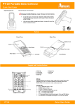
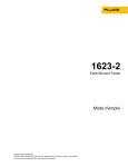
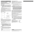
XCell SureLock™ Mini-Cell For leak-free electrophoresis of mini-gels Catalog nos. EI0001, EI0020, EI0002 Rev. Date: 6 May 2010 Manual part no. IM-9003 MAN0000739 Corporate Headquarters 5791 Van Allen Way Carlsbad, CA 92008 T: 1 760 603 7200 F: 1 760 602 6500 E: [email protected] For country-specific contact information visit our web site at www.invitrogen.com User Manual Table of Contents Kit Contents .................................................................................................ii Product Specifications ................................................................................ 1 Description of Parts..................................................................................... 3 Assembling the XCell SureLock™ Mini-Cell.............................................. 5 Gel Electrophoresis Protocol...................................................................... 8 Disassembling the XCell SureLock™ Mini-Cell....................................... 10 Troubleshooting ........................................................................................ 12 Buffers and Running Conditions ............................................................ 13 Related Products........................................................................................ 15 Technical Support ..................................................................................... 17 Purchaser Notification.............................................................................. 18 Safety Information..................................................................................... 19 Sicherheits-Anweisungen......................................................................... 21 Instructions de securite............................................................................. 22 i Kit Contents Types of Kits This manual is supplied with the following kits: Kit XCell SureLock™ Mini-Cell SureLock Retrofit Kit for XCell II™ Mini-Cell XCell SureLock™ Mini-Cell with XCell II™ Blot Module Kit Kit Components Cat. no. EI0001 EI0020 EI0002 The components included with the different kits are listed below. See page 3 for more details. Kit Components ™ XCell SureLock Mini-Cell Gel Tension Wedge (1 each) Buffer Dam (1 each) Lower Buffer Chamber (1 each) Buffer Core (1 each) Mini-Cell Lid (1 each) Gel Knife (1 each) SureLock Retrofit Kit for XCell II™ Mini-Cell Gel Tension Wedge (1 each) Buffer Dam (1 each) SureLock Mini-Cell Lid (1 each) XCell SureLock™ Mini-Cell with XCell II™ Blot Module Kit EI0001 XCell II™ Blot Module Safety Information See page 19 for safety information and explanation of symbols used on the instrument. Intended Use For research use only. Not intended for any animal or human therapeutic or diagnostic use. ii Product Specifications Product Description The XCell SureLock™ Mini-Cell’s unique design allows you to run mini-gels quickly, easily, and leak-free without any clamps or grease. The set-up time is only 30 seconds; just drop the Buffer Core and the Gel Tension Wedge into the Lower Buffer Chamber, insert the gels, and pull the Gel Tension Wedge forward. The perfect no-leak seal results in no mess and consistent performance. Tough polycarbonate construction of the unit boosts durability. Retractable plugs, recessed jacks, and a specially designed lid enhance user safety. You can transfer with the optional XCell II™ Blot Module (Cat. No. EI9051), using the same Lower Buffer Chamber. Mini-Cell Lid Buffer Dam Buffer Core Gel Tension Wedge Lower Buffer Chamber Continued on next page 1 Product Specifications, Continued XCell SureLock™ Mini-Cell Specifications Dimensions: 11 × 12 × 16 cm Upper Buffer Chamber Capacity: 200 mL Lower Buffer Chamber Capacity: 600 mL Material: Polycarbonate Electrode Wire: Platinum (0.010”diameter) Electrical Limits: 1,500 VDC or 75 Watts Temperature Limit: 70°C ™ The XCell SureLock Mini-Cell is impervious to alcohol, but not compatible with chlorinated hydrocarbons (e.g., chloroform), aromatic hydrocarbons (e.g., toluene, benzene) or acetone. Gel Specifications Sample Well Capacity Gel Cassette: 10 cm × 10 cm Thickness: 1.0 mm or 1.5 mm Gel Size: 8 cm × 8 cm Combs: 1 well, 2D well, 5 well, 9 well, 10 well, 15 well, and 17 well The maximum recommended sample volume/well for different Novex® mini-gels is listed below. For additional details on loading volumes and maximum protein load, refer to the Novex® Pre-Cast Gel Electrophoresis Guide or the NuPAGE® Technical Guide. Gel Thickness 1 well 1.0 mm 700 L 400 L 60 L 1.5 mm N/A 600 L N/A 2 2D well 5 well 9 well 10 well 15 well 17 well 28 L 25 L 15 L 15 L N/A 37 L 25 L 25 L Description of Parts Introduction The various parts included with the XCell SureLock™ Mini-Cell are described below. See page 15 for ordering information. Lower Buffer Chamber Cat no. EI0013 Buffer Core Cat no. EI9014 The Lower Buffer Chamber has a capacity of approximately 800 mL of buffer and is used as a heat sink during the electrophoresis of proteins. Buffer Core contains platinum electrodes, gold terminals, and silicone gaskets Cell Safety Lid with Cables Cat no. EI0010 Continued on next page 3 Description of Parts, Continued Gel Tension Wedge Cat no. EI0011 Buffer Dam Cat no. EI0012 The positive locking action of the Gel Tension Wedge ensures trouble-free, leakfree electrophoresis of protein gels. Push the lever on the Gel Tension Wedge forward into a locked position to generate an even horizontal force which seals the gel cassette/Buffer Core assembly firmly into position in the lower buffer chamber Use the Buffer Dam when you need to run only one Novex® gel. Gel Knife 4 Cat no. EI9010 Assembling the XCell SureLock™ Mini-Cell Removing Gel Cassette 1. Cut open the gel cassette pouch with scissors and remove cassette. 2. Drain away the gel packaging buffer. 3. Remove the gel cassette from the pouch and rinse with deionized water. Note: Always handle the cassette by its edges only. Always wear protective clothing when performing laboratory experiments. To avoid contamination from possible residual acrylamide, wear protective gloves when loading and unloading the XCell SureLock™ Mini-Cell and when preparing, staining/destaining, and drying gels. Procedure 1. Peel off the tape covering the slot on the back of the gel cassette. 2. In one fluid motion, pull the comb out of the cassette. This exposes the gel loading wells. 3. Use a pipette to gently wash the cassette wells with 1X running buffer. Invert the gel and shake to remove buffer. Repeat twice. Fill the sample wells with running buffer. Note: Be sure to displace all air bubbles from the cassette wells as they will affect sample running. 4. Lower the Buffer Core into the Lower Buffer Chamber so that the negative electrode fits into the opening in the gold plate on the Lower Buffer Chamber as shown in the figure. Buffer Core Lower Buffer Chamber Lower Buffer Chamber and Buffer Core Front View Continued on next page 5 Assembling the XCell SureLock™ MiniCell, Continued Procedure, continued 5. Insert the Gel Tension Wedge into the XCell SureLock™ behind the buffer core. Make sure the Gel Tension Wedge is in its unlocked position (see next page), allowing the wedge to slip easily into the XCell SureLock™ unit. The Gel Tension Wedge should rest on the bottom of the Lower Buffer Chamber. 6. Insert gel cassettes into the lower buffer chamber. Place one cassette behind the core and one cassette in front of the core. For each cassette, the shorter “well” side of the cassette faces in towards the buffer core. The slot on the back of the cassette must face out towards the lower buffer chamber (see figure below). Buffer Core Notch faces in Second Gel or Buffer Dam Cassette Slot faces out Side View 7. If you are running only one gel, replace the rear gel cassette with the Buffer Dam. Continued on next page 6 Assembling the XCell SureLock™ MiniCell, Continued Procedure, continued 8. Pull forward on the Gel Tension Lever in a direction towards the front of the XCell SureLock™ unit until lever comes to a firm stop and the gels or gel/buffer dam appear snug against the buffer core (see figure below). Locked Position Unlocked Position Buffer Core Lower (anode) Buffer Chamber Front Gel Buffer Core Gel Tension Wedge unlocked Rear Gel Lower (anode) Buffer Chamber Front Gel Gel Tension Wedge locked Rear Gel When fully assembled, cassettes and Buffer Core are in place and Gel Tension Wedge is locked into position. Review the information provided on page 12 to troubleshoot your experiments. 7 Gel Electrophoresis Protocol Sample Loading 1. Prepare your samples using the appropriate sample buffer at the desired protein concentration. 2. Prepare the appropriate running buffer (see page 13). 3. The Upper Buffer Chamber (cathode) is the void formed between the two gel cassettes (or one cassette and the buffer dam) on each side of the buffer core. 4. Fill the Upper Buffer Chamber with 200 mL of the appropriate running buffer (see page 13). Use enough running buffer to completely cover the sample wells. 5. Ensure that the Upper Buffer Chamber is not leaking. If the level of running buffer drops, the electrophoresis core and cassettes are not properly seated. Repeat steps 6 and 7 on page 6. 6. Use the pipette equipped with a round sample loading tip (Cat. no. LC1001) to underlay the samples into the gel wells (see figure below). Lower the tip to the bottom of the sample well and slowly pipet sample into well without contaminating another well with the sample. If you have difficulty distinguishing the sample wells when loading the sample, see Troubleshooting. Note: To obtain the best results and promote a uniform running of the stacking front, load sample buffer in all the wells, whether or not they contain samples. Pipet with sample Running Buffer Sample Sample Well Continued on next page 8 Gel Electrophoresis Protocol, Continued Procedure 1. Fill the Lower Buffer Chamber (anode) by pouring 600 mL of running buffer through the gap between the Gel Tension Wedge and the back of the Lower Buffer Chamber as shown in the figure below. Note: If you are using Tricine and NuPAGE® Gels, we recommend that you fill the lower buffer chamber completely (600 mL) as this will help dissipate heat during the run. For other gel types, a filled lower buffer chamber is recommended, but not required. The XCell SureLock™ Mini-Cell will function as long as the lower buffer chamber is filled enough to cover the slot at the bottom of the cassette. 2. Align the lid on the Buffer Core. The lid can only be firmly seated if the (-) electrode is aligned over the banana plug on the right. If the lid is not properly seated, no power will go through the mini-cell. 3. With the power off, connect the electrode cords to power supply {red to (+) jack, black to (-) jack}. Caution: Power must be off before connecting the XCell SureLock™ Mini-Cell to the power supply. 4. Turn on the power. See page 13 for running conditions for different gel types. 9 Disassembling the XCell SureLock™ MiniCell Procedure 1. At the end of the run, turn off the power and disconnect the cables from the power supply. 2. Remove the lid and unlock the Gel Tension Lever. There is no need to remove the Gel Tension Wedge. 3. Remove the gel cassettes from the mini-cell. Handle gel cassettes by their edges only. 4. Lay the gel cassettes (well side up) on a flat surface, such as the benchtop. Allow one edge to hang ~1 cm over the side of the benchtop. 5. Carefully insert the Gel Knife’s beveled edge into the narrow gap between the two plates of the cassette. Note: Do not push the knife forcefully between the cassette plates or you may cut into the gel. 6. Push up and down gently on the knife’s handle to separate the plates. You will hear a cracking sound which means you have broken the bonds which hold the plates together. Repeat until you have broken the bonds on one side. 7. Rotate the cassette and repeat Steps 5-6, until the two plates are completely separated. 8. Upon opening the cassette, the gel may adhere to either side. Remove and discard the plate without the gel, allowing the gel to remain on the other plate. 9. If blotting, proceed to the Western Transfer Protocol without removing the gel from the plate (refer to IM-9051 for more details). Note: Trying to remove the gel at this point may result in the gel tearing. Proceed to Step 11. Continued on next page 10 Disassembling the XCell SureLock™ MiniCell, Continued Procedure, continued 10. If staining, remove the gel from the cassette plate by one of the two methods: If the gel remains on the shorter (notched) plate, use the sharp edge of the Gel Knife to remove the bottom foot of the gel. Hold the Gel Knife at a 90° angle to the gel and the slotted cassette plate. Push straight down on the knife to cut the gel. Repeat the motion across the gel to cut the entire foot. Hold the cassette plate and gel over a container with the gel facing downward. Use the knife to carefully loosen one lower corner of the gel and allow the gel to peel away from the plate. Gel knife 90° angle Gel foot Pre-cast gel Cassette plate If the gel remains on the longer (slotted) plate, hold the cassette plate and gel over a container with the gel facing downward. Gently push the gel knife through the slot in the cassette, until the gel peels away from the plate. Cut the foot off the gel after fixing and staining, but before drying. 11. Immediately fix, stain or transfer the gel as desired. Maintenance Wash the XCell SureLock™ Mini-Cell with a mild detergent and rinse with deionized water after each use. 11 Troubleshooting Problem Cause Solution Buffers are too dilute Check buffer recipe; remake if necessary. Upper buffer chamber is leaking Make sure the buffer core is firmly seated, the gaskets are in place and the gel tension lever is locked. Voltage is set too low. Set correct voltage. Tape left on the bottom of the cassette Remove tape from bottom of cassette. Connection to power supply not complete Check all connections with a voltmeter for conductance. Insufficient buffer level Make sure the upper buffer (cathode) is covering the wells of the gel. Be sure there is sufficient buffer in the Lower Buffer Chamber to cover the slot at the bottom of the gel. Run is faster than normal with poor resolution Buffers are too concentrated or incorrect. Check buffer recipe; dilute or re-make if necessary. Voltage, current, or wattage is set at a higher limit Decrease power conditions to recommended running conditions (see page 13). Cannot see the sample wells to load sample There is little contrast between the sample well and the rest of the gel Mark cassette at the bottom of the wells with a marker pen prior to assembling the Upper Buffer Chamber. Illuminate the bench area with a light source placed directly behind the XCell SureLock™ unit. Run taking longer than usual Current reading on power supply is zero or very low 12 Appendix Buffers and Running Conditions Introduction Gel Type The buffers and running conditions for the different Novex® mini-gels using the XCell SureLock™ Mini-Cell are listed below. For ordering information on buffers, see page 15. Sample Buffer Running Buffer Power Settings* Run Time Tris-Glycine SDS Running Buffer (LC2675) Voltage: 125 V Constant Expected Current: Start: 30–40 mA End: 8–12 mA 90 minutes Tris-Glycine SDS-PAGE (denaturing, nonreducing) Tris-Glycine SDS Sample Buffer (LC2676) Tris-Glycine SDS-PAGE (denaturing, reducing) Add NuPAGE® Sample Reducing Agent (NP0004) Tris-Glycine (Native) Tris-Glycine Native Sample Buffer (LC2673) Tris-Glycine Native Running Buffer (LC2672) Voltage: 125V Constant Expected Current: Start: 6–12 mA End: 3–6 mA 1–12 hours NuPAGE® Bis-Tris SDSPAGE (denaturing, nonreducing) NuPAGE® LDS Sample Buffer (NP0007) NuPAGE® MES SDS Running Buffer (NP0002) or NuPAGE® MOPS SDS Running Buffer (NP0001) Voltage: 200V Constant Expected Current: Start: 110–125 mA End: 70–80 mA 35–50 minutes NuPAGE® Bis-Tris SDSPAGE (denaturing, reducing) Add NuPAGE® Sample Reducing Agent (NP0004) to sample buffer Add NuPAGE® Antioxidant (NP0005) to running buffer NuPAGE® Tris-Acetate SDS-PAGE (denaturing) NuPAGE® LDS Sample Buffer (NP0007) NuPAGE® TrisAcetate Running Buffer (LA0041) Voltage: 150V Constant Expected Current: Start: 40–55 mA End: 25–40 mA 50 minutes Add NuPAGE® NuPAGE® Tris-Acetate Sample SDS-PAGE Reducing Agent (denaturing, (NP0004) to reducing) sample buffer *Current readings are per gel Add NuPAGE® Antioxidant (NP0005) to running buffer Continued on next page 13 Buffers and Running Conditions, Continued Gel Type Sample Buffer Running Buffer Power Settings* Run Time Tricine SDSPAGE (denaturing, non-reducing) Tricine SDS Sample Buffer (LC1676) Tricine SDS Running Buffer (LC1675) Voltage: 125V Constant Expected Current: Start: 80 mA End: 40 mA 90 minutes Zymogram Tris-Glycine SDS Sample Buffer (LC2676) Tris-Glycine SDS Running Buffer (LC2675) Voltage: 125V Constant Expected Current: Start: 30-40 mA End: 8–12 mA 90 minutes IEF pH 3–7 IEF pH 3–7 Sample Buffer (LC5371) IEF pH 3–7 Cathode Buffer (LC5370) IEF Anode Buffer (LC5300) Voltage: 100V 1 hour 200V 1 hour 500V 30 minutes Expected Current: Start: 5 mA End: 6 mA 2.5 hours IEF pH 3–10 IEF pH 3–10 Sample Buffer (LC5311) IEF pH 3–10 Cathode Buffer (LC5310) IEF Anode Buffer (LC5300) Voltage: 100V 1 hour 200V 1 hour 500V 30 minutes Expected Current: Start: 5 mA End: 6 mA 2.5 hours TBE Hi-Density TBE Sample Buffer (LC6678) TBE Running Buffer (LC6675) Voltage: 200V Constant Expected Current: Start: 10–18 mA End: 4–6 mA 30–90 minutes TBE-Urea TBE-Urea Sample Buffer (LC6876) or Prep TBE-Urea Sample Buffer (LC6877) TBE Running Buffer (LC6675) Voltage: 180V Constant Expected Current: Start: 10–20 mA End: 6–14 mA 50–75 minutes DNA Retardation Hi-Density TBE Sample Buffer (LC6678) TBE Running Buffer (LC6675) at 1/2 X concentration Voltage: 100V Constant Expected Current: Start: 12–15 mA End: 6–15 mA 90 minutes *Current readings are per gel 14 Related Products Many of the components of the XCell SureLock™ MiniCell, as well as additional reagents that may be used for electrophoresis of proteins are available separately from Invitrogen. Ordering information is provided below. For details, visit www.invitrogen.com or call Technical Support (page 17). Additional Products Apparatus ™ XCell SureLock Mini-Cell ™ Quantity Cat. no. 1 kit EI0001 SureLock Retrofit Kit for XCell II Mini-Cell 1 kit EI0020 XCell SureLock™ Mini-Cell w/XCell II™ Mini-Cell 1 kit EI0002 XCell II™ Blot Module 1 EI9051 PowerEase 500 Power Supply 1 EI8600 Replacement Parts Quantity Cat. no. Lower Buffer Chamber 1 EI0013 Gel Tension Wedge 1 EI0011 ® Gel Knife 1 EI9010 Buffer Core with Electrodes 1 EI9014 Lid with Cables 1 EI0010 Buffer Dam 1 EI0012 Buffer Core Replacement Wire 2 EI9022 Gaskets for EI0001 and EI9051 2 EI9016 Repair Kit for Buffer Core (includes wire, wire insulation, post, nut washer) 1 Kit EI9021 Pipette Tips for Gel Loading Quantity Cat. no. Gel Loading Tips (Standard Round) 200/pk LC1001 Flat Gel Loading Tips 200/pk LC1002 Gel Loading Tips (Eppendorf Round) 200/pk LC1010 Continued on next page 15 Related Products, Continued Pre-Mixed Buffers Quantity Cat. no. ® 10 mL NP0007 ® 250 L NP0004 10 mL NP0009 NuPAGE LDS Sample Buffer (4X) NuPAGE Sample Reducing Agent (10X) ® NuPAGE Antioxidant 15 mL NP0005 NuPAGE® MOPS SDS Running Buffer (20X) 500 mL NP0001 NuPAGE® MES SDS Running Buffer (20X) 500 mL NP0002 ® 500 mL LA0041 ® NuPAGE Tris-Acetate SDS Running Buffer (20X) NuPAGE Transfer Buffer (20X) 125 mL NP0006 ® 500 mL LC2675 ® 20 mL LC2676 Novex Tris-Glycine SDS Running Buffer (10X) Novex Tris-Glycine SDS Sample Buffer (2X) ® Novex Tris-Glycine Native Running Buffer (10X) 500 mL LC2672 Novex® Tris-Glycine Native Sample Buffer (2X) 20 mL LC2673 Novex® Tris-Glycine Transfer Buffer (25X) 500 mL LC3675 ® 500 mL LC1675 ® 20 mL LC1676 ® 125 mL LC5310 ® 125 mL LC5370 ® Novex IEF Anode Buffer, for both pH ranges (50X) 100 mL LC5300 Novex® IEF Sample Buffer pH 3-10 (2X) 25 mL LC5311 ® 25 mL LC5371 ® 1L LC6675 ® 10 mL LC6678 ® 10 mL LC6876 ® Novex Prep TBE-Urea Sample Buffer (2X) 20 mL LC6877 Novex® Zymogram Renaturing Buffer (10X) 500 mL LC2670 Novex® Zymogram Developing Buffer (10X) 500 mL LC2671 Novex Tricine SDS Running Buffer (10X) Novex Tricine SDS Sample Buffer (2X) Novex IEF Cathode Buffer pH 3-10 (10X) Novex IEF Cathode Buffer pH 3-7 (10X) Novex IEF Sample Buffer pH 3-7 (2X) Novex TBE Running Buffer (5X) Novex Hi-Density TBE Sample Buffer (5X) Novex TBE-Urea Sample Buffer (2X) 16 Technical Support World Wide Web Contact Us Visit the Invitrogen website at www.invitrogen.com for: Technical resources, including manuals, vector maps and sequences, application notes, SDSs, FAQs, formulations, citations, handbooks, etc. Complete technical support contact information Access to the Invitrogen Online Catalog Additional product information and special offers For more information or technical assistance, call, write, fax, or email. Additional international offices are listed on our web page (www.invitrogen.com). Corporate Headquarters: European Headquarters: 5791 Van Allen Way Inchinnan Business Park Carlsbad, CA 92008 USA 3 Fountain Drive Tel: 1 760 603 7200 Paisley PA4 9RF, UK Tel (Toll Free): 1 800 955 6288 Tel: +44 (0) 141 814 6100 Fax: 1 760 602 6500 Tech Fax: +44 (0) 141 814 6117 E-mail: [email protected] E-mail: [email protected] 17 Purchaser Notification Limited Use Label License No. 5: Invitrogen Technology 18 The purchase of this product conveys to the buyer the nontransferable right to use the purchased amount of the product and components of the product in research conducted by the buyer (whether the buyer is an academic or for-profit entity). The buyer cannot sell or otherwise transfer (a) this product (b) its components or (c) materials made using this product or its components to a third party or otherwise use this product or its components or materials made using this product or its components for Commercial Purposes. The buyer may transfer information or materials made through the use of this product to a scientific collaborator, provided that such transfer is not for any Commercial Purpose, and that such collaborator agrees in writing (a) not to transfer such materials to any third party, and (b) to use such transferred materials and/or information solely for research and not for Commercial Purposes. Commercial Purposes means any activity by a party for consideration and may include, but is not limited to: (1) use of the product or its components in manufacturing; (2) use of the product or its components to provide a service, information, or data; (3) use of the product or its components for therapeutic, diagnostic or prophylactic purposes; or (4) resale of the product or its components, whether or not such product or its components are resold for use in research. For products that are subject to multiple limited use label licenses, the terms of the most restrictive limited use label license shall control. Life Technologies Corporation will not assert a claim against the buyer of infringement of patents owned or controlled by Life Technologies Corporation which cover this product based upon the manufacture, use or sale of a therapeutic, clinical diagnostic, vaccine or prophylactic product developed in research by the buyer in which this product or its components was employed, provided that neither this product nor any of its components was used in the manufacture of such product. If the purchaser is not willing to accept the limitations of this limited use statement, Life Technologies is willing to accept return of the product with a full refund. For information about purchasing a license to use this product or the technology embedded in it for any use other than for research use please contact Out Licensing, Life Technologies, 5791 Van Allen Way, Carlsbad, California 92008 or [email protected] Appendix B: Safety Safety Information Safety During operation, the XCell SureLock™ Mini-Cell must be used with an external DC power supply designed specifically for electrophoresis applications. This power supply must be isolated from ground so that the DC output is floating. The PowerEase™ 500 Programmable Power Supply (page 15) meets these requirements. The maximum electrical operating parameters for the XCell SureLock™ Mini-Cell are: Maximum Voltage Limit: Maximum Power Limit: 1500 VDC* 75 Watts* Maximum Operating Temperature Limit: 70C ™ The XCell SureLock Mini-Cell’s lid is designed such that if the lid is removed, the electrical connection to the unit will be broken. Do not attempt to use the cell without the cell lid. Do not use lids from other mini-cells. The XCell SureLock™ Mini-Cell is designed to meet EN61010-1 Safety Standards. This product is safe to use when operated in accordance with this instruction manual. If this unit is used or modified in a manner not specified in this manual then protection afforded by the unit will be impaired. Alteration of this unit will: Void the warranty. Void the EN61010-1 safety standard certification. Create a potential safety hazard. Invitrogen is not responsible for any injury or damage caused by use of this unit when operated for purposes which it is not intended. All repairs and service should be performed by Invitrogen. The XCell SureLock™ Mini-Cell is classified as Class II of IEC 536 for protection against electrical shock. *The XCell SureLock™ is rated at 1500 VDC, 75 Watts, but for running protein gels, the maximum voltage/wattage recommended is 500 VDC/50 Watts. Continued on next page 19 Safety Information, Continued Symbols on Instrument The following table describes the symbols displayed on the instrument. Informational The symbols used on the XCell SureLock™ Mini-Cell are explained below: Symbols Used on the XCell SureLock™ Mini-Cell to indicate an area where a potential shock hazard may exist. Used on the XCell SureLock™ Mini-Cell to indicate a warning. The operator’s manual should be consulted to avoid possible personal injury or instrument damage. WEEE (Waste Electrical and Electronic Equipment) symbol indicates that this product should not be disposed of in unsorted municipal waste. Follow local municipal waste ordinances for proper disposal provisions to reduce the environmental impact of WEEE. Visit www.invitrogen.com/weee for collection and recycling options. Important The XCell SureLock™ Mini-Cell is manufactured in the USA from domestic and International components. To ensure safe, reliable operation, always operate the XCell SureLock™ Mini-Cell according to instructions provided in this manual. Wear protective gloves and safety glasses when working in a laboratory environment. Invitrogen products are intended for in vitro use only. Invitrogen is not responsible for injuries or damages caused by improper use. 20 Sicherheits-Anweisungen SicherheitsAnweisungen Die SureLock™ Elektrophorese-Zelle mub mit einer geerdeten Gleichstrom-Spannungsquelle betrieben werden, die speziell für die Elektrophorese entwickelt wurde. Um eine Gefährdung des Benutzers auszuschlieben, sollten folgende Laufbedingungen eingehalten werden: Maximale Spannung: 1500 Volt Maximale Leistung: 75 Watt Maximale Temperatur: 70°C Beim Entfernen des Kammerdeckels der SureLock™ ElectrophoreseZelle wird der Stromflub unterbrochen. Die Benutzung der Zelle ohne Deckel ist verboten. Die SureLock™ Elektrophorese-Zelle entspricht den SicherheitsRichtlinien EN 61010-1. Es besteht keinerlei Gefährdung für den Benutzer, wenn die Richtlinien der Gebrauchsanweisung eingehalten werden. Wird die Elektophorese-Zelle in einer Art und Weise benutzt bzw. modifiziert, die nicht in der Gebrauchsanleitung beschrieben ist, werden die Sicherheitvorkehrugen zum Schutz des Betreibers beeinträchtigt. Bei unsachgemäber Handhabung entfallen alle Garantieansprüche und Sicherheitszulassungen (EN61010-1). Invitrogen haftet nicht für Verletzungen oder Schäden jeglicher Art, wenn die Elektrophorese-Zelle für Anwendungen eingesetzt wird, für die die Zelle nicht entwickelt wurde. Alle Reparaturen und Wartungen müssen von Invitrogen oder einem von Invitrogen authorisierten Händler vorgenommen werden. Das Gehäuse der SureLock™ Elektrophorese-Zelle besteht aus Kunststoff und enthält keine leitenden Teile. Die QuickPoint™ Elektrophorese-Zelle ist gegen Stromschlag nach der IEC 536 – Norm in Klasse II eingestuft. Symbolerklärung Weist auf eine Zone hin, wo Gefährdung durch Stromschlag besteht. Lesen Sie die Bedienungsanleitung, um Verletzungen oder Beschädigung des Gerätes zu vermeiden. WEEE (Waste Electrical and Electronic Equipment) 21 Instructions de securite Instructions de securite La Cellule d'Electrophorése SureLock™ doit être uniquement une utilisation avec une alimentation en courant contimu DC externe et spécialement conçue pour en électrophorése. Cette alimentation doit être avec séparation galvanique de façon que la sortie DC du secondaire ai un potentiel électrique flottant. Le domaine d'utilisation de la Celleule d'Electrophorése SureLock™ est limité par les paramétres de fontctionnement suivants: Tension maximum: 1,500 V continu Puissance maximum: 75 W Tempèrature maximum: 70°C La Cellule d'Electrophorése SureLock™ est conçue de façon á ce que lorsque le couvercle de la cuve est ouvert, la connection électrique avec l'unité est interrompue. Il ne faut en aucun cas essayer de faire fonctionner la cuve sans le couvercle. La Cellule d'Electrophorése SureLock™ satisfait aux normes de sécurité EN 61010-1. La sécurité est assurée dans tous les cas d'une utilisation conforme au manuel d'utilisation. Dans le cas ou la cellule serait modifiée ou utilisée de manière non spécifiée dans le manuel d'utilisation, la sécurité de l'utilisateur pourrait être remise en cause. En cas d'utilisation non conforme toutes les garanties sinsi que les certifications de conformité aux normes de sécurité sont abrogeès. La responsabilité de Invitrogen ne péut être mise en cause en cas d' accident et dommages causés par une utilisation non conforme de la Cellue d'Electrophorése. Toute intervention de service ou de réparation doit être unquement effectuée par Invitrogen ou par un agent agrée de Invitrogen. La Cellule d'Electrophorése SureLock™ est classifié par rapport à la norme d'isolation électrique IEC 536 en classe II. Signification des pictogrammes Sur le Cellule d'Electrophorése XCell SureLock™, signale les zones où un risque de choc électrique peut exister. Sur le Cellule d'Electrophorése XCell SureLock™, signale un risque potentiel pour l’utilisateur ou pour l’equipement. Veuillez consulter le mode d’emploi. WEEE (Waste Electrical and Electronic Equipment) ©2010 Life Technologies Corporation. All rights reserved. The trademarks mentioned herein are the property of Life Technologies Corporation or their respective owners. 22 Corporate Headquarters 5791 Van Allen Way Carlsbad, CA 92008 T: 1 760 603 7200 F: 1 760 602 6500 E: [email protected] For country-specific contact information visit our web site at www.invitrogen.com User Manual