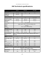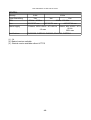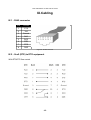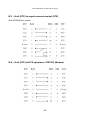
1
XC-31, XC-310, XC-4100
User MANUAL
Version 1.2
DECISION Europe 3 rue de Lattre de Tassigny BP14 85170 ST DENIS LA CHEVASSE
FRANCE
Tel : (33) 02 51 41 41 89 - Fax : (33) 02 51 41 41 90
Web : http://www.xcell.com/ - E-mail : [email protected]
User manual XC-31 XC-310 XC-4100
Table des matières
I.Introduction......................................................................5
I.1 - XC-31- 310 - 4100 serial ports server's serie...................................5
I.2 - Furnished features.............................................................................5
I.3 - Symbolics...........................................................................................5
II.Xcell overview.................................................................7
II.1 - XC-32..................................................................................................7
II.2 - XC-320................................................................................................7
II.3 - XC-4200..............................................................................................7
III.Installation......................................................................8
III.1 - Indicating LEDS of XC-31................................................................8
III.2 - Indicating LEDS of XC-310..............................................................9
III.3 - indicating LEDS of XC-4100..........................................................10
III.4 - Ports and interfaces of XC-31.......................................................11
III.5 - Ports and interfaces of XC-310.....................................................11
III.6 - Ports and interfaces of XC-4100 ..................................................11
III.7 - Cautions..........................................................................................11
III.7.1 - Cleaning XC.................................................................................................11
III.7.2 - Note..............................................................................................................12
III.7.2.1 - About XC-31...........................................................................................12
III.7.2.2 - General note..........................................................................................12
IV.Configuration...............................................................13
IV.1 - Introduction....................................................................................13
IV.2 - Entering IP address.......................................................................13
IV.2.1 - Entering IP address from Xcell administrator..........................................13
IV.2.2 - Entering IP address from a terminal.........................................................14
IV.3 - HTTP Configuration (Netscape, Internet Explorer).....................14
IV.4 - Network interface..........................................................................16
IV.4.1 - Identification................................................................................................16
IV.4.2 - Route checking with PING command.......................................................16
IV.4.3 - Routing table...............................................................................................17
IV.5 - Asynchronous interfaces..............................................................18
IV.5.1 - Software settings........................................................................................18
IV.5.2 - Asynchronous port mode..........................................................................19
IV.5.3 - Type of control............................................................................................19
IV.5.4 - Flow control.................................................................................................20
IV.5.5 - Automatic disconnection of a Modem......................................................20
IV.5.6 - Association of a modem form to a port....................................................21
IV.5.7 - AutoUser mode...........................................................................................21
IV.6 - Saving and restoring Xcell configuration....................................21
IV.6.1 - Saving in FLASH memory..........................................................................21
IV.6.2 - Saving a configuration copy......................................................................21
IV.7 - Audit...............................................................................................22
-2-
User manual XC-31 XC-310 XC-4100
IV.7.1 - Audit on a remote machine........................................................................22
IV.7.2 - Audit on your console................................................................................23
IV.7.3 - Audit in a file...............................................................................................23
IV.7.4 - List of created audits..................................................................................24
IV.7.5 - Delete audit..................................................................................................24
IV.7.6 - Start/stop audit............................................................................................24
V.Rawtty and RemoteCOM..............................................26
V.1 - Introduction.....................................................................................26
V.2 - RemoteCOM....................................................................................26
V.2.1 - RemoteCOM under Windows 95/98............................................................26
V.2.1.1 - Setting up the XC-31- 310 - 4100...........................................................26
V.2.1.2 - Installation of RemoteCOM driver...........................................................27
V.2.2 - RemoteCOM under Windows NT system...................................................30
V.2.2.1 - Setting up the XC-31- 310 - 4100...........................................................30
V.2.2.2 - Installation of RemoteCOM driver...........................................................31
V.2.2.3 - Displaying RemoteCOM service status..................................................33
V.3 - Rawtty..............................................................................................34
V.3.1 - Server configuration....................................................................................34
V.3.2 - Setting up the XC.........................................................................................35
V.3.3 - rawtty, rawclose...........................................................................................35
VI.Mux mode.....................................................................37
VI.1 - Introduction....................................................................................37
VI.2 - TCP Mux.........................................................................................37
VI.3 - UDP Mux.........................................................................................37
VI.4 - Example n°1: Remote management of a PLC by a technician. . .37
VI.4.1 - Description..................................................................................................37
VI.4.2 - Configuration of client's side XC...............................................................38
VI.4.3 - Configuration of server's side XC.............................................................39
VI.5 - Example n°2: Remote management of a PLC by more than one
technician (solution 1)............................................................................39
VI.5.1 - Description..................................................................................................39
VI.5.2 - Solution........................................................................................................40
VI.5.3 - Configuration of client's side Xcell...........................................................41
VI.5.4 - Configuration of server's side Xcell..........................................................41
VI.6 - Example n°3: Remote management of a PLC by more than one
technician (solution 2)............................................................................42
VI.6.1 - Description..................................................................................................42
VI.6.2 - Solution........................................................................................................42
VI.6.3 - Configuration of client's side Xcell...........................................................43
VI.6.4 - Configuration of server side's XC.............................................................44
VI.7 - Example n°4: Remote management of a PLC by more than one
technician (solution 3)............................................................................44
VI.7.1 - Description..................................................................................................44
VI.7.2 - Solution........................................................................................................45
VI.7.3 - Configuration of client's side Xcell...........................................................46
VI.7.4 - Configuration of server's side XC.............................................................47
-3-
User manual XC-31 XC-310 XC-4100
VII.Advanced functions....................................................47
VII.1 - DHCP.............................................................................................47
VII.1.1 - Definition....................................................................................................47
VII.1.2 - DHCP client................................................................................................48
VII.1.3 - DHCP relay.................................................................................................48
VIII.Technical specifications...........................................50
IX.Cabling..........................................................................52
IX.1 - RJ45 connector..............................................................................52
IX.2 - Xcell (DTE) to DTE equipment......................................................52
IX.3 - Xcell (DTE) to asynchronous terminal (DTE)...............................53
IX.4 - Xcell (DTE) to DCE equipment - RS232C (Modem).....................53
IX.5 - Xcell (DTE) to DCE equipment - RS422A.....................................54
IX.6 - Xcell (DTE) to DCE equipment - RS485........................................55
-4-
User manual XC-31 XC-310 XC-4100
I.Introduction
I.1 - XC-31- 310 - 4100 serial ports server's serie
A serial ports server provides real COM ports on the Ethernet network. You can use
modems, barcodes readers or any serial device on the Ethernet network.
Thanks to the Mux mode, you can also establish a communication between to serial
equipments through an asynchronous link. You can, for example, use a terminal on your
Xcell to manage a PLC located on a remote Xcell.
Serial ports server's family is composed by the following products :
p
p
p
XC-31 provides 2 asynchronous ports (RS232C) and one Ethernet port.
XC-310 provides 4 or 8 asynchronous ports (RS232C or RS422/485A) and one
Ethernet port.
XC-4100 provides 4, 8, 12 or 16 asynchronous ports (RS232C or RS422/485A) and
one Ethernet port.
I.2 - Furnished features
You will find the following features with any Xcell :
p
p
p
p
p
A document titled "Getting started with Xcell server/router".
Xcell Technology CD-ROM contains RemoteCOM drivers, Rawtty drivers and a few
usefull softs. Please read the readme.html file for more information.
A DTE DB25 cable (ref F00132) and a DTE DB9 cable (ref F00142). These cables are
PC COM port compatible - RS232C).
A power supply cable.
A 5V power supply (XC-31 and XC-310 only)
I.3 - Symbolics
In all pictures of this documentation, we will use the following symbols :
-5-
User manual XC-31 XC-310 XC-4100
WAN Link
Printer
Ethernet Network
Modem
Lan link
Aquisition de
données
Work
Portable
computer
Serial port server
function / Raw Mode
Gateway
Terminal server
function
Remote access
router function
Mux Mode function
Server
-6-
User manual XC-31 XC-310 XC-4100
II.Xcell overview
II.1 - XC-32
XC-31 provides 2 asynchronous ports. Thanks to the "raw" function of Xcell, you can
connect printers or any other serial equipment (bar-code reader, data acquisition system,
a.s.o...).
Just run on your Unix server the "rawtty" application (or RemoteCom on Windows NT and
95) to redirect the in and out data flow of the specified communication port ('COMx' or
'/dev/ttyx' following the operating system) to one of XC-310 port.
Thanks to the Mux mode, you can also establish a communication between to serial
equipments through an asynchronous link. You can, for example, use a terminal on your
Xcell to manage a PLC located on a remote Xcell.
II.2 - XC-320
XC-310 supports the same functions as XC-31 but provides 4 or 8 asynchronous ports.
II.3 - XC-4200
XC-4100 supports the same functions as XC-310 but provides 4, 8, 12 or 16
asynchronous ports. XC-4100 also uses the XC-4 architecture.
Figure 1 - Using of Xcell to connect serial equipments.
-7-
User manual XC-31 XC-310 XC-4100
III.Installation
This chapter details the first steps to install XC-31, XC-310, XC-4100
III.1 - Indicating LEDS of XC-31
XC 31
The top face of XC-is composed by a line of five LEDS
Designation
Color
State
Meaning
On
Setup mode activated
Off
Normal mode
Setup - Locate
Red
Link
Red
TxD
Green
Data transmission To the network
RxD
Green
Data reception from the network
Power
Green
Clignotemen
Locate function activated
t
On
No presence of the network
Off
Presence of the network
On
Xcell is on
Off
Xcell is off
-8-
User manual XC-31 XC-310 XC-4100
III.2 - Indicating LEDS of XC-310
XC 310
The front panel of XC-310composed by a line of five LEDS
Designatio
n
Setup
Color
Red
State
On
Setup mode activated
Off
Normal mode
Blinking
LAN Link
Red
Meaning
Locate function activated
On
No presence of the network
Off
Presence of the network
LAN Tx
Green
Data transmission from the network
LAN Rx
Green
Data reception from the network
Power
Green
On
Xcell is on
Off
Xcell is off
-9-
User manual XC-31 XC-310 XC-4100
III.3 - indicating LEDS of XC-4100
XC 4100
The front panel of XC-4100 is composed by a line of seven LEDS.
Designation
Setup
Color
Red
State
Meaning
On
Setup mode activated
Off
Normal mode
Blinking
Sync - Fan
fault
Orange
On
One synchrone interface actived at
least
Off
No synchrone interface activated
Blinking
Isdn-Fan fault
Green
Red
Fan fault
On
One isdn interface activated at least
Off
No isdn interface activated
Blinking
Link
Locate function activated
Fan fault
On
No presence of the network
Off
Presence of the network
Tx
Orange
Data transmission from the network
Rx
Green
Data reception from the network
-10-
User manual XC-31 XC-310 XC-4100
III.4 - Ports and interfaces of XC-31
The rear face of XC-31 displays the followings elements :
p
p
p
1 power supply connector.
1 Ethernet port 10baseT.
The front face of XC-31 displays the following elements :
2 asynchronous ports RS232C/V24 noted ''Serial 1
The port n°1 is the console port in setup mode
III.5 - Ports and interfaces of XC-310
The rear face of XC-310 displays the followings elements :
1 power supply connector.
1 Ethernet port 10baseT.
4 or 8 asynchronous ports (RS232C/V24 or RS422/485A)
The port n°1 is the console port in setup mode
p
p
p
III.6 - Ports and interfaces of XC-4100
The rear face of XC-4100 displays the followings elements :
p
p
p
1 power supply connector.
1 Ethernet port 10baseT.
1 on/off button
The front face of XC-4100 displays the following elements :
p
p
p
4, 8, 12 or 16 asynchronous ports (RS232C/V24 or RS422/485A)
1 asynchronous port noted ''Serial 1/Console''.
1 port ''Serial 2''
III.7 - Cautions
The opening of the box is strictly reserved to persons authorized by Decision Europe.
Manipulation of the open box is forbidden.
III.7.1 - Cleaning XC
p
p
Remove the power supply cable from the rear panel
Please use watertown.
-11-
User manual XC-31 XC-310 XC-4100
p
Caution : do not use chemical products which can damage the box paint (Alcohol,
trichlo,.. )
Please be sure the box is completely dry before powering on.
III.7.2 - Note
III.7.2.1 - About XC-31
Security of this equipment is guaranteed only if you use the furnished power supply or an
equivalent model.
Cables must only be plug at very low security voltages (VLSV).
Warning
This is a class A product. In a domestic environment this product may cause radio
interference in which case the user may be required to take adequate measures.
III.7.2.2 - General note
The hardware and software described in this document may change without warning.
The information in this document may change without warning. Xcell Technology reserves
itself the right to revise this publication without having to provide notification for such
revisions. Aslong as reasonable precautions have been taken, Xcell Technology assumes
no responsibility for errors that may appear in this document.
Xcell Technology is a registered trademark of DECISION Europe.
No part of this publication may be copied or reproduced in any form or by means without
prior written consent of Xcell Technology.
Windows and Microsoft Windows are trademarks of Microsoft Corporation. Ethernet is a
trademark of the Xerox corporation. Netscape is a trademark of Netscape
Communications Corporation.
All other brand and product names and trademarks mentioned herein are trademarks of
their respective owners.
-12-
User manual XC-31 XC-310 XC-4100
IV.Configuration
IV.1 - Introduction
The three ways to configure your Xcell are :
p
p
p
With an asynchronous terminal (or a terminal emulator) connected to one of its serial
ports.
From another network host using Telnet protocol.
From a web browser (Netscape, Internet Explorer,...).
Before using Telnet or HTTP protocols, you just need to fix Xcell IP address. This can be
made with Xcell administrator or with a terminal.
IV.2 - Entering IP address
IV.2.1 - Entering IP address from Xcell administrator
Xcell administrator enables you to locate and setup all Xcells of your LAN.
To search for all Xcells on your LAN, click on "Adminstration" then on "Explorer". A
window like this one must appears on your screen :
To change Xcell's IP address, click on "IP address" cell and type new IP adress.
-13-
User manual XC-31 XC-310 XC-4100
IV.2.2 - Entering IP address from a terminal
Use a terminal ( 9600 bauds, 8 bits, no parity ) connected on Xcell's Console part.
The Setup mode can be selected after Xcell startup. When the Setup LED blinks, press
three times on '@' :
The terminal screen should display the following message :
ROOT>>
Now, you have access to a classic line shell (with a vt100, vt220, ansi terminal). Data input
errors may be corrected by using 'left arrow ', 'right arrow' and 'backspace’ keys. The 'up
arrow' and 'down arrow' keys re-edit the last command.
You can now enter IP address and the network where your Xcell is connected, with the
following commands :
IFCONFIG IP <interface> <IP_address>
ROUTE ADD NET <interface> <destination> <gateway> <netmask>
Example :
ROOT>> ifconfig ip eth0 192.168.1.11
Ok!
ROOT>> route add net eth0 192.168.1.0 0.0.0.0 255.255.255.0
Ok!
To save your configuration parameters, it is necessary to write it in permanent memory
(FLASH-EPROM). Enter the save command to do achieve this :
ROOT>> save
Status: Done.
ROOT>>
IV.3 - HTTP Configuration (Netscape, Internet Explorer)
Xcell can be configured in text mode (Console, Telnet) or in graphic mode (HTTP).
The following pages of this manual excusively deal with a text mode configuration.
However, all text mode commands have their equivalents in graphic mode.
To set up parameters in graphic mode, you just need a web browser (Netscape, Internet
Explorer), and to enter Xcell's IP address in URL field :
-14-
User manual XC-31 XC-310 XC-4100
Click on GO, and open a session under the name root. Default password is root.
Now you can configure your Xcell.
-15-
User manual XC-31 XC-310 XC-4100
IV.4 - Network interface
IV.4.1 - Identification
To correctly initialize the network connection, use the ifconfig command to enter the
following parameters :
p
p
p
p
IP address. The location of your Xcell on the network. This address consists in four
numbers separated by dots (.), valid values for each of the four numbers are whole
numbers between 1 and 254, for example "192.168.2.3".
Network mask (netmask). It is a number similar to IP address, which determines what
address is specified by the network and what place on this network is specified by your
Xcell. For an IP address "192.168.2.3", if you enter 255.255.255.0" as a mask value,
this means that your network address is "192.168.2.0".
The maximal transfer unit system (MTU). On an Ethernet system the MTU value is
commonly established at 1500.
Broadcast address. By default, this address is the one of the system with 255 in place
of the machine address. For a network address "192.168.2.0", broadcast address will
be "192.168.2.255".
By default, network mask is configured at "255.255.255.0" (class C) and the MTU at 1500
(Ethernet). Only in some particular cases, you have to change these values.
IV.4.2 - Route checking with PING command
In order to check if Xcell is can be reached inside the network, you can run the ping
command :
ROOT>> ping 192.168.1.20
machine IP address on the
network
PING 192.168.1.20 (192.168.1.20): 56 data bytes
64 bytes from 192.168.1.20: icmp_seq=0 ttl=255 time=0.6 ms
64 bytes from 192.168.1.20: icmp_seq=1 ttl=255 time=38.2 ms
64 bytes from 192.168.1.20: icmp_seq=2 ttl=255 time=2.7 ms
64 bytes from 192.168.1.20: icmp_seq=3 ttl=255 time=2.7 ms
64 bytes from 192.168.1.20: icmp_seq=4 ttl=255 time=2.8 ms
--- 192.168.1.20 ping statistics --5 packets transmitted, 5 packets received, 0% packet loss
round-trip min/avg/max = 0.6/9.4/38.2 ms
ROOT>
IV.4.3 - Routing table
-16-
User manual XC-31 XC-310 XC-4100
Before sending an IP frame, Xcell consults its routing table in order to find an entry
indicating the route to use.
In the following example, terminals connect to server thanks to Xcell.
Note that the server is to be found on the sub-network 192.168.1.0 at the address
192.168.1.2 and that Xcell belongs to the sub-network 192.168.2.0 at the address
192.168.2.2. A bridge helps to the interconnection of the two sub-networks :
Figure 2 - Network example to make a routing table
To send IP frames to server, you must necessarily inform Xcell that these frames run
through the 192.168.2.1 router.
There are three manners for this :
The first consists in informing Xcell that all IP frames intended for the 192.168.1.2 server
have to be sent to the 192.168.2.1 router :
ROOT>> route add host eth0 192.168.1.2 192.168.2.1 255.255.255.255
Ok!
ROOT>> route static
Kernel routing table
Destination
Gateway
Genmask
Typ
Iface
192.168.1.2
192.168.2.1
255.255.255.255
host
eth0
The second consists in informing Xcell that all IP frames intended for the 192.168.1.0
network have to be transmitted to the 192.168.2.1 router :
ROOT>> route add net eth0 192.168.1.0 192.168.2.1 255.255.255.0
Ok!
ROOT>> route static
Kernel routing table
Destination
Gateway
Genmask
Typ
Iface
192.168.2.0
0.0.0.0
255.255.255.0
net
eth0
-17-
User manual XC-31 XC-310 XC-4100
192.168.1.0
192.168.2.1
255.255.255.255
net
eth0
The third, (and most often used manner) consists in informing Xcell that, if the routing
table does not contain any entry corresponding to the IP frame to send, then this one will
be sent (by default) to the 192.168.2.1 router :
ROOT>> route add net eth0 0.0.0.0 192.168.2.1
Ok!
ROOT>> route static
Kernel routing table
Destination
Gateway
Genmask
192.168.2.0
0.0.0.0
255.255.255.0
0.0.0.0
192.168.2.1
0.0.0.0
0.0.0.0
Typ
net
net
Iface
eth0
eth0
IV.5 - Asynchronous interfaces
IV.5.1 - Software settings
Configuration of a serial port can be done with serial command :
You must enter individually each parameter :
ROOT>>
ROOT>>
ROOT>>
ROOT>>
serial
serial
serial
serial
speed 9600 4
csize 8 4
parity none 4
stopb 1 4
Port 4 can then be setup to 9600 bauds, without parity control, with a 8 bits data width and
one stop bit.
To set the port speed of ports 3, 6 and 7 to 19200 bps, type the following command :
ROOT>> serial speed 19200 3 6 7
To set all ports to 38400 bps, enter the following command :
ROOT>> serial speed 38400 all
To set all ports but ports 3 and 5 to 4800 bps, enter :
ROOT>> serial speed 4800 all 3 5
You can see, at every time, all current ports parameters with the following command :
ROOT>> serial show all
-18-
User manual XC-31 XC-310 XC-4100
IV.5.2 - Asynchronous port mode
Each asynchronous port can work in one of the following modes (regardless of the other
ports configurations) :
Terminal mode
Connection of an asynchronous terminal
(Telnet).
Printer mode
Connection of a printer (LPD).
Raw mode
Connection of a passive equipment
(RemoteCOM or rawTTY).
PPP mode
Connection of a remote host to a network or
remote networks interconnection.
(asynchronous PPP).
Rtelnet mode
Access through a TCP/IP network to an
equipment or to an operating system not
equiped with the TCP/IP protocol.
For example, to program the first five Xcell ports in each of these modes, commands
would respectively be :
ROOT
Ok!
ROOT
Ok!
ROOT
Ok!
ROOT
Ok!
ROOT
Ok!
>> serial mode term 1
>> serial mode printer 2
>> serial mode raw 3
>> serial mode ppp 4
>> serial mode rtelnet 5
IV.5.3 - Type of control
A port can be configured in local control or in modem control. In modem control, Xcell will
ignore state of the DCD signal for this port. On the other hand, in modem control, Xcell will
propose to open a session only if the DCD is active. Moreover, if the DCD signal becomes
inactive, Xcell will close all the open sessions on this port.
To configurate port 3 in local control, enter:
ROOT>> serial linectrl local 3
To use a modem on port 2, you have to setup the port with this command :
ROOT>> serial linectrl modem 2
-19-
User manual XC-31 XC-310 XC-4100
IV.5.4 - Flow control
Flow control can have four different values :
Soft control
XON/XOFF. Sending of XON(11H) and XOFF(13H)
characters.
Hard control
RTS/CTS. Signal shift.
Soft and hard control
No control
XON/XOFF and RTS/CTS. This kind of flow control is
used when one want to connect a serial printer on a
port.
No flow control will be performed.
For example, to set up the first four ports of Xcell in each of these flow control modes, you
have to enter the following commands :
ROOT>>
Ok!
ROOT>>
Ok!
ROOT>>
Ok!
ROOT>>
Ok!
serial flowctrl soft 1
serial flowctrl hard 2
serial flowctrl softhard 3
serial flowctrl none 4
IV.5.5 - Automatic disconnection of a Modem
If there is no data traffic during a determined deplay on port where the modem is
connected, Xcell can decide to disconnect the modem (DTR signal deasserted).
For example, to disconnect the modem installed on port 3 if this one is not used during 2
mn, use the following command :
ROOT>> serial timeout 120 3
To disable this option, please set a delay of 0 second.
WARNING !! This automatic disconnection is sometimes managed directly by the modem.
IV.5.6 - Association of a modem form to a port
To use a modem on a port, you have to associate a modem form to this part. A modem
form contains configuration parameters for the modem (see IV-8 Management of a
modem connection).
To associate a modem form named "gen33600" to port 1, enter :
-20-
User manual XC-31 XC-310 XC-4100
ROOT>> serial modem gen33600 1
IV.5.7 - AutoUser mode
AutoUser mode enables Xcell to launch automatically a session on the specified port for a
certain user. To configure Xcell's port 1 in AutoUser mode for a user named "Paul", enter :
ROOT>> serial autouser paul 1
CAUTION !! You must definitely not define any password for the session lauching to be
automatical. (see IV.7 - Creation of a user.).
To come back to usual mode on port 1, enter :
ROOT>> serial autouser none 1
Consult reference manual for more details about commands that are dealt with in this
chapter.
IV.6 - Saving and restoring Xcell configuration
IV.6.1 - Saving in FLASH memory
All parameters are conserved by Xcell in RAM, up to the next Xcell boot. If you want to
conserve all your parameters, you must write them in FLASH memory. Make this
operation with the following command :
ROOT>> save
Status: done.
ROOT>>
IV.6.2 - Saving a configuration copy
You can save a Xcell configuration copy on a remote machine ; thanks to the TFTP (trivial
file transfer protocol) protocol. Xcell parameters will be sent via TFTP to a file previously
created on the remote machine.
Proceed as follows :
Create an empty file on your TFTP server, example with the following UNIX command :
echo -n > /tmp/xcell.conf
chmod 666 /tmp/xcell.conf
-21-
User manual XC-31 XC-310 XC-4100
Indicate to Xcell the IP address of the server where the file will be staved, as well as the
name of this file and start the transfer :
ROOT>> system config server 192.168.1.1
ROOT>> system config path "/tmp/xcell.conf"
ROOT>> system config store
To restore configuration file, execute the next command :
ROOT>> system config load
CAUTION !! The loaded configuration is stocked in RAM. Save it in FLASH memory with
the save command :
ROOT>> save
Status: Done.
ROOT>>
IV.7 - Audit
Audits generate some usefull information to control Xcell's activity or to analyse
configuration errors. These information are displayed in real time or redirected a file. Audit
commands enable you to set type and level of captured information, as well as the
displaying mode of information.
IV.7.1 - Audit on a remote machine
To create an audit on a remote machine, use the audit add command with following
parameters :
AUDIT ADD <syslog | trap> <remote IP> <level> <type>
Syslog / Trap : if you use syslog option , information will be sent to syslogd daemon of
the specified remote machine. If your machine does not run syslogd daemon, you must
install one.
If you use an smtp administration soft, you can display Xcell's audit thanks to the trap
option.
p
p
Remote IP : It is the IP address of the remote machine on which you will display Xcell's
audit.
p
Level : It is preciseness level of audit messages. These differents levels are
-22-
User manual XC-31 XC-310 XC-4100
warning
notice
Minimum (displaying of errors
messages).
Like warning level but there is messages
about Xcell's activity.
info
Like notice level with more detailled
messages about running process.
debug
All existing messages with maximum
details.
Type : It defines type of messages that you want to see in audit. These differents types
are
system
async
Messages about system
parameters (DHCP, RADIUS,
save, ...).
Messages about asynchronous
ports.
net
Messages about network
all
All preceeding types.
IV.7.2 - Audit on your console
To create audit on your console, use the audit add console command in this way :
AUDIT ADD console <level> <type>
Audit will display in your current session's window. You will still be able to enter
commands with this shell.
Level and type parameters do not change.
IV.7.3 - Audit in a file
To send auditin a file, use the audit add buffer command in this way :
AUDIT ADD buffer <level> <type>
Level and type parameters do not change.
You will be able to show this file thanks to audit view and audit last commands. The
audit view command enables you to show the entire audit file.
ROOT>> audit view
-23-
User manual XC-31 XC-310 XC-4100
With the audit last command, you can display the last lines of the audit file :
ROOT>> audit last 10
In this example, you will show the ten last lines of the audit file.
IV.7.4 - List of created audits
The audit show command enables you to display the list of declared audits. Example :
ROOT>> audit show
buffer
0.0.0.0
debug
: async
warning :net system
console 0.0.0.0
warning : all
IV.7.5 - Delete audit
To delete an audit, use one of the following commands :
AUDIT DELETE <syslog | trap> <remote IP> <level> <type>
AUDIT DELETE <buffer | console> <level> <type>
IV.7.6 - Start/stop audit
When you create an audit with the audit add command, it is immediatly actived. But you
must restart a console audit after any reboot of your Xcell. This can be made thanks to the
audit start command :
ROOT>> audit start
Ok!
To stop a console audit, use the audit stop command :
ROOT>> audit stop
Ok!
-24-
User manual XC-31 XC-310 XC-4100
V.Rawtty and RemoteCOM
V.1 - Introduction
Rawtty and RemoteCOM enable a server to use an Xcell asynchronous port as one of its
own ports. To perform this operation, you just have to install a driver on server and to
setup a few parameters on your Xcell.
V.2 - RemoteCOM
RemoteCOM is a driver for Windows systems which enables you to redirect COM ports on
Xcell. RemoteCOM is made to manage flow control signals (DTR, DSR and DCD).
V.2.1 - RemoteCOM under Windows 95/98
V.2.1.1 - Setting up the XC-31- 310 - 4100
Only flow control parameter must be set on the Xcell.
Configuration example with Telnet console :
First, display current ports configuration :
ROOT>> serial show all
Port Mode Speed FlowCtrl LineC Cs Par. Stop ModemName Rtelnet
Time0
1
raw 9600 soft
local 8 none 1
2001
2
raw 9600 soft
local 8 none 1
2002
0
0
If you want to set hard flow control on ports 1 and 2, enter :
ROOT>> serial flowctrl hard 1 2
Then, reset ports with new parameters :
ROOT>> reset port 1 2
Display ports configuration again to see if new parameters are well set :
ROOT>> serial show all
Port Mode Speed FlowCtrl LineC Cs Par. Stop ModemName RtelnetTime0
1
raw 9600 hard
local 8 none 1
2001
0
-25-
User manual XC-31 XC-310 XC-4100
2
raw
9600
hard
local 8
none 1
2002
0
Speed, parity, csize and stop bit are send by RemoteCOM to the Xcell.
RemoteCOM transmits DTR signal and recepts states of DCD and DSR signals.
V.2.1.2 - Installation of RemoteCOM driver
1 - To install RemoteCom driver, open Windows's control panel.
p
p
p
p
p
Click on "Add new hardware"
Ask "No" to Windows's automatic detection.
Click on "Others".
Then click on "Have disk" and find the way to the path in which you have make a copy
of RemoteCOM driver (remcom.inf).
Restart Windows after the installation of the first RemoteCOM port.
2 - Choosing COM port number.
When your system is restarted :
p
p
p
In the control panel, click on "system" and device control tab.
Click on "RemoteCOM(tm)" in the menu "Ports(COM&LPT)" and choose the COM
port's number associated to the RemoteCOM port.
Click on "Refresh", the "RemoteCOM(tm)" label will changes in "COMx".
-26-
User manual XC-31 XC-310 XC-4100
3 - RemoteCOM configuration.
p
p
p
In the device control tab, click on "RemoteCOM(COMx)" in the menu
"Ports(COM&LPT)".
Click on "properties", then change Xcell's IP address and Xcell's port number.
Example : Xcell 192.168.4.23, port 7.
4 - Using RemoteCom.
You can audit RemoteCOM activity using the RemoteCOM application (icon in the task
bar).
p
p
p
p
p
p
Click on RemoteCOM icon.
Click on "Status".
Displaying of connections and associated COM ports.
Displaying of connections/disconnections and errors (log file).
Displaying of transmitted/received datas in real time.
Displaying of active datas.
-27-
User manual XC-31 XC-310 XC-4100
5 - Installating another RemoteCOM port
p
p
p
p
p
p
p
Control panel.
Add new hardware.
Ask "No" to Windows's automatic detection.
Click on "Ports(COM & LPT)".
Choose DECISION EUROPE ->;RemoteCOM(tm).
Restart your system.
Return to step 2 Choosing COM port number.
6 - Troubleshooting.
p
p
p
Check if Xcell is visible on the network. (using ping or telnet).
Check configuration and state of Xcell's port.
Read the log file.
V.2.2 - RemoteCOM under Windows NT system
V.2.2.1 - Setting up the XC-31- 310 - 4100
Only flow control parameter must be set on the Xcell.
Configuration example with Telnet console :
First, display current ports configuration :
ROOT>> serial show all
Port Mode Speed FlowCtrl LineC Cs Par. Stop ModemName RtelnetTime0
1
raw 9600 soft
local 8 none 1
2001
0
2
raw 9600 soft
local 8 none 1
2002
0
-28-
User manual XC-31 XC-310 XC-4100
If you want to set hard flow control on ports 1 and 2, enter :
ROOT>> serial flowctrl hard 1 2
Then, reset ports with new parameters :
ROOT>> reset port 1 2
Display ports configuration again to see if new parameters are well set :
ROOT>> serial show all
Port Mode Speed FlowCtrl LineC Cs Par. Stop ModemName Rtelnet
Time0
1
raw 9600 hard
local 8 none 1
2001
2
raw 9600 hard
local 8 none 1
2002
0
0
Speed, parity, csize and stop bit are send by RemoteCOM to the Xcell.
RemoteCOM transmits DTR signal and recepts states of DCD and DSR signals.
V.2.2.2 - Installation of RemoteCOM driver
RemoteCOM for WINNT is composed of :
p
p
p
A service module: RemoteCOM(service).
A driver : RemoteCOM(driver).
A program for setup, audit and control of RemoteCOM service.
WARNING : Do not mistake RemoteCOM service and RemoteCOM driver (that is also a
service). This one is automatically started and stopped by RemoteCOM service.
To install RemoteCOM, click on the "Setup" file of the installation disk/path.
p
p
p
p
p
p
p
p
Restart your system.
In the "Start" menu, click on :
Programs ->; RemoteCOM ->; RemoteCOM Administration.
Click on "Edit" in the main menu.
Create : select "Create".
Enter XC's IP address (ex : 192.168.4.23) , XC's port number (ex : 7), WINDOWS
device (ex : COM3) and connection's parameters.
Change : select "View&Modify".
Delete : select "Delete".
-29-
User manual XC-31 XC-310 XC-4100
Opening timeout : Default parameter is 10 secondes (rarely modified).
WARNING : You must add some timeouts created by the network. Results of the
connection trie can come after the open timeout delay.
Keepalive : Enables you to detect any error on the network link.
0 means that KEEPALIVE is stopped. A too small value uselessly overloads the network
(15 seconds is a "good" value).
Keep the connection : The network connection will be established at start of
RemoteCOM service. The port will not be used by another station.
Restart connection if error : Automatically restart connection (with a delay of 10
seconds) after a disconnection performed by remote Xcell. RemoteCOM will try to restart
connection every 10 seconds.
Packet mode : Synchronise application that is use RemoteCOM with data flow. The
"data transmitted"(EV_TXEMPTY in WaitCommEvent()) label is right only when
transmitted data have really been send by the remote port.
The "COMSTAT.cbOutQue" field in ClearCommError() is updated in the same way.
Note : With FAX CLASS 1 modem, this mode (used with a buffer size of 128 bytes) make
possible reception and transmission of FAX.
Signals/data synchronised mode : Activate this mode to transmit all signals (TX, RX,
RTS,CTS,DTR,DSR,DCD) synchronised with data. You must not activate flow control to
use this mode.
Buffers size : 1 to 4096 octets
Default size is 2048 (value 0 or 2048).
In some cases, application seems to have send all data but these data are in buffers. If
the application stops the connection before all data have been transmitted, you can
reduce buffers size to fix this problem.
Overhelming of inter-character timeout : 0 to 500 milliseconds.
The Network cut data into several packets. Then, characters of a same "logical" frame (ex:
reply message of a modem ) can be divide and received with an higher delay than delay
of a standard COM port. If you use inter characters timeout option of windows's COM
-30-
User manual XC-31 XC-310 XC-4100
ports, you may have to use this option too.
WARNING : Any modification will be effective after a restart of RemoteCOM service. If
RemoteCOM service is already running, you must stop and restart it.
In the main menu, click on "Service", then click on "Start" (or "Stop" and "Start").
Note : When you have just finished RemoteCOM installation, RemoteCOM service is
disable.
The first time you will restart your system, RemoteCOM will warn you and then you will be
able to choose the activation mode of RemoteCOM service.
You can change service activation mode service at any time with WINNT services control
panel.
V.2.2.3 - Displaying RemoteCOM service status
Click on Service -> parameters
p
p
Select COM port you want display.
Check log box if you want keep information in a file.
p
p
Be sure that RemoteCOM is not used by any application.
Click on Service ->Stop
Click on Service ->Start to reset RemoteCOM with new parameters.
p
Click on Status -> View in the main menu
-31-
User manual XC-31 XC-310 XC-4100
V.3 - Rawtty
V.3.1 - Server configuration
Installation example for a rawTTY device driver on UNIX SCO Open Server :
#./install.sh
Xcell rawTTY installation
Xcell IP address ? ? : 192.168.1.42
>;>;192.168.1.42 Ok [RET,ÆOÆ] Non [æNÆ] DEL-exit ? O
PORTS in RAW mode (ex: 1 2 7 (enter) ) ? : 5 6
>;>; ( 5 6 ) Ok [RET,ÆOÆ] Non [æNÆ] DEL-exit ? O
kernel relinking is running (...)
Ok
INFO:
- REBOOT your system to update
- default logins are off
ttys names are : /dev/tag
use the SCO command : enable to active the logins
-32-
User manual XC-31 XC-310 XC-4100
ex: enable tag01 tag02 tag07
V.3.2 - Setting up the XC
On Xcell, you must setup the corresponding port(s) in "raw" mode:
ROOT>>
ROOT>>
ROOT>>
ROOT>>
ROOT>>
ROOT>>
serial mode raw 5 6
serial speed 9600 5 6
serial parity none 5 6
serial csize 8 5 6
serial stopb 1 5 6
reset port 5 6
V.3.3 - rawtty, rawclose
On a UNIX server, with rawtty and rawclose commands , you can adjust some
parameters of the "Rawtty" function.
WARNING !! These two commands must not be used when the Driver has been installed !
The syntax of the rawtty command is :
rawtty [-keepalive <;delay>;] [-v1] [-d] [-u username] [-c] device xcell_IP port_num
Keepalive helps to regularly check Xcell's physical presence on the network.
A request is carried out every <delay>; second(s), to check if the connection is still valid. If
there is no answer within this time range, connection is cut down.
p
p
p
p
"-v1" option enables to use command with Xcell versions previous to the 3.2 version.
"-d" option enables to enter in debug mode.
"-u" option enables to create a device under another user account.
"-c" option enables to cancel created device, (ex: /dev/raw1), at the end of the rawtty
process.
Two commands enable to increase or to decrease delay of the connected keepalive :
The first command increase keepalive delay with one second.
kill -USR1 pid_rawtty
The second decrease keepalive delay with one second.
kill -USR2 pid_rawtty
Example for a UNIX server:
rawtty /dev/raw4
192.168.1.12
5 &
-33-
User manual XC-31 XC-310 XC-4100
The rawclose command enables to force to close port declared in "rawtty". Syntax:
rawclose server_IP_address
port_number
Example :
rawclose 192.168.1.12 5
-34-
User manual XC-31 XC-310 XC-4100
VI.Mux mode
VI.1 - Introduction
Mux mode enables you to establish an asynchronous link from end to end through an IP
network.
To make this possible, data (composed by characters and changes of signal's states) are
separated into packets. These packets are then transmitted, thanks to TCP or UDP
transfert's protocols, from one serial port to the other.
VI.2 - TCP Mux
The TCP protocol warrants retransmission of lost or mistaken data and manages packets.
This mode must be used in most of the cases.
To configure this connection, you must set the 'client' port in mux mode and the 'server'
port in raw mode.
VI.3 - UDP Mux
To transmit the data flow that forwards the asynchronous link from one end of the network
to the other, we must change this data flow in a characters flow mixed with codes which
match with signal's states. Packaging of data and forwarding of an IP network can
generate delays between characters and changes of signal states if they are in different
packets. It means that out data flow and in data flow can have mismatching
chronogrammes. It can disrupt the good running of some serial transmission's protocols
like ones used in industrial environment.
Thanks to a measured delay between in data flow and out data flow, UDP mux mode
enables most of transmission's protocols to use a connection through an IP network. To
configure this connection, you must set both ports in mux_dg mode.
VI.4 - Example n°1: Remote management of a PLC by a technician
VI.4.1 - Description
A technician wants to manage a PLC located on a remote TCP/IP network thanks to a
terminal (or a terminal emulator).
-35-
User manual XC-31 XC-310 XC-4100
VI.4.2 - Configuration of client's side XC
ROOT>> serial mode mux 1
Ok!
ROOT>> mux ip 192.168.2.1 1
Ok!
ROOT>> mux port 1 1
Ok!
ROOT>> mux dsrredirect none 1
Ok!
ROOT>> mux ctsredirect none 1
Ok!
ROOT>> mux show 1
Port Mode Sync Flush KAlive Remote( IP, port)DCD->DSR->CTS->debug
-----------------------------------------------------------------1
mux No
Yes
0
192.168.2.1 1
none none none No
ROOT>> serial show 1
Port Mode Speed FlowCtrl LineC Cs Par. Stop ModemName RtelnetTimeO
-----------------------------------------------------------------1
mux 9600 soft
local 8 none 1
2001
0
VI.4.3 - Configuration of server's side XC
-36-
User manual XC-31 XC-310 XC-4100
ROOT>> serial mode raw 1
Ok!
ROOT>> mux dsrredirect none 1
Ok!
ROOT>> mux ctsredirect none 1
Ok!
ROOT>> mux show 1
Port Mode Sync Flush KAlive Remote( IP, port)DCD->DSR->CTS->debug
-----------------------------------------------------------------1
raw No
Yes
0
0.0.0.0
0
none none none No
ROOT>> serial show 1
Port Mode Speed FlowCtrl LineC Cs Par. Stop ModemName RtelnetTimeO
-----------------------------------------------------------------1
raw 9600 soft
local 8 none 1
2001
0
VI.5 - Example n°2: Remote management of a PLC by more than one
technician (solution 1)
VI.5.1 - Description
Two technicians each have a terminal and they want to manage, one after the other, a
PLC located on a remote TCP/IP network.
-37-
User manual XC-31 XC-310 XC-4100
VI.5.2 - Solution
You cannot establish two mux TCP connections to the same destination port at the same
time.
To solve this problem, we will establish each mux TCP connection only when technician's
terminal will be powered.
The technician must power off his terminal to permit the other technician to manage the
PLC.
When a terminal is powered, there is at least one signal activated (RTS for a terminal or
DTR for a terminal emulator). You just have to link this signal to serial port's DCD entry of
Xcell and to configure management of DCD signal by Xcell (serial linectrl modem). TCP
connection will be established only if terminal is powered. This connection will be stopped
if DCD signal is not on (terminal is off).
VI.5.3 - Configuration of client's side Xcell
Make a cable with terminal's RTS (or DTR) signal linked on serial port's DCD signal.
ROOT>> serial mode mux 1
Ok!
ROOT>> serial linectrl modem 1
Ok!
ROOT>> mux ip 192.168.2.1 1
Ok!
ROOT>> mux port 1 1
Ok!
ROOT>> mux dsrredirect none 1
Ok!
ROOT>> mux ctsredirect none 1
Ok!
ROOT>> mux show 1
Port Mode Sync Flush KAlive Remote( IP, port)DCD->DSR->CTS-> debug
-----------------------------------------------------------------1
mux No
Yes
0
192.168.2.1 1
none none none No
ROOT>> serial show 1
Port Mode Speed FlowCtrl LineC Cs Par. Stop ModemName RtelnetTimeO
------------------------------------------------------------------38-
User manual XC-31 XC-310 XC-4100
1
mux
9600
soft
modem 8
none 1
2001
0
VI.5.4 - Configuration of server's side Xcell
ROOT>> serial mode raw 1
Ok!
ROOT>> mux dsrredirect none 1
Ok!
ROOT>> mux ctsredirect none 1
Ok!
ROOT>> mux show 1
Port Mode Sync Flush KAlive Remote( IP, port)DCD->DSR->CTS->debug
-----------------------------------------------------------------1
raw No
Yes
0
0.0.0.0
0
none
none none No
ROOT>> serial show 1
Port Mode Speed FlowCtrl LineC Cs Par. Stop ModemName RtelnetTimeO
-----------------------------------------------------------------1
raw 9600 soft
local 8 none 1
2001
0
VI.6 - Example n°3: Remote management of a PLC by more than one
technician (solution 2)
VI.6.1 - Description
-39-
User manual XC-31 XC-310 XC-4100
VI.6.2 - Solution
The solution above needs that the technician powers off his terminal to allow another
technician to manage the PLC. If the first technician forgets to power off his terminal, the
PLC is not reachable for the second technician. Another solution is to automatically break
the unused connection after a specified timeout.
Connection will be automatically relaunched when the technician will type any character
on his keyboard.
On client's side Xcell :
p
p
p
p
p
Link terminal's DTR signal and DCD signal of serial port n°1(make a cable).
Activate DTR signal on port n°1 (mux defaultdtr yes 1).
Configure management of DCD signal by Xcell (serial linectrl modem 1).
Configure Xcell to wait a character before launching the connection (serial quick no 1).
Specify the timeout delay of the unused connection (serial timeout 180 1).
On server's side Xcell :
p
Be sure that DTR signal state on client Xcell will not be changed by DSR signal state of
server Xcell (mux dsrredirect none 1).
-40-
User manual XC-31 XC-310 XC-4100
Two conditions must be satisfied to establish the connection :
p
p
DCD signal on : DTR is on and is linked to DCD of the serial port, the condition will
ever be satisfied. But we must be sure that no change of client XC's DTR signal's state
occurs. It is the reason why we stop redirection of DSR signal (mux dsrredirect none 1).
Receive a character : thanks to the serial quick no command, Xcell will wait for a
character on its serial port before establishing the connection.
VI.6.3 - Configuration of client's side Xcell
ROOT>> serial mode mux 1
Ok!
ROOT>> serial linectrl modem 1
Ok!
ROOT>> serial timeout 180 1
Ok!
ROOT>> serial quick no 1
Ok!
ROOT>> mux defaultdtr yes 1
Ok!
ROOT>> mux ip 192.168.2.1 1
Ok!
ROOT>> mux port 1 1
Ok!
ROOT>> mux dsrredirect none 1
Ok!
ROOT>> mux ctsredirect none 1
Ok!
ROOT>> mux show 1
Port Mode Sync Flush KAlive Remote( IP, port) DCD-> DSR-> CTS->
debug
-------------------------------------------------------------------1
mux No
Yes
0
192.168.2.1 1
none
none none No
ROOT>> serial show 1
Port Mode Speed FlowCtrl LineC Cs Par. Stop ModemName RtelnetTimeO
-----------------------------------------------------------------1
mux 9600 soft
modem 8 none 1
2001
180
-41-
User manual XC-31 XC-310 XC-4100
VI.6.4 - Configuration of server side's XC
ROOT>> serial mode raw 1
Ok!
ROOT>> mux dsrredirect none 1
Ok!
ROOT>> mux ctsredirect none 1
Ok!
ROOT>> mux show 1
Port Mode Sync Flush KAlive Remote( IP, port) DCD->DSR->CTS->debug
-----------------------------------------------------------------1
raw No
Yes
0
0.0.0.0
0
none
none none No
ROOT>> serial show 1
Port Mode Speed FlowCtrl LineC Cs Par. Stop ModemName RtelnetTimeO
-----------------------------------------------------------------1
raw 9600 soft
local 8 none 1
2001
0
VI.7 - Example n°4: Remote management of a PLC by more than one
technician (solution 3)
VI.7.1 - Description
-42-
User manual XC-31 XC-310 XC-4100
VI.7.2 - Solution
The solution above assign the PLC to a technician for a minimum of 3 minutes, even if his
terminal is off.
This solution have all advantages of the two preceeding solutions. Access to the PLC will
be assigned to the first technician who will try to establish the connection. If the technician
power off his terminal, the PLC will be immediatly accessible to the second technician.
One the other hand, if the technician forgets to power off his terminal, the PLC will be
accessible to the second technician after 3 minutes.
On client's side Xcell :
p
p
p
p
p
p
p
Link DTR (or RTS) signal of the terminal to DSR signal of serial port n°1 (make a
cable).
Enable redirection of DSR signal to DTR signal of server Xcell (mux dsrredirect dtr 1).
Link DTR signal and DCD signal of serial port n°1 (make a cable).
Activate DTR signal of serial port n°1 (mux defaultdtr yes 1).
Configure management of DCD signal by Xcell (serial linectrl modem 1).
Configure Xcell to wait a character before launching the connection (serial quick no 1).
Specify the timeout delay of the unused connection (serial timeout 180 1).
On server's side Xcell :
p
p
p
Link DTR signal and DSR signal of serial port n°1 (make a cable).
Activate DTR signal of serial port n°1 (mux defaultdtr yes 1).
Enable redirection of DSR signal to DTR signal of client Xcell (mux dsrredirect dtr 1).
DSR signals of client and server's Xcell must absolutly be activated at startup. If DSR
signal on client's side Xcell is not activated at startup, Xcell can't establish the initial
connection.
Moreover, an undetermined DSR signal on server's side Xcell can force client Xcell to
break initial connection before this connection can be established.
State of DTR (or RTS) signal on the terminal will be applied to DCD on client Xcell. This
Xcell will be able to establish or break the connection matching with terminal state (on or
off).
Others parameters (serial quick yes and serial timeout 180) allow to start the
-43-
User manual XC-31 XC-310 XC-4100
connection only if Xcell is receive a character.
VI.7.3 - Configuration of client's side Xcell
ROOT>> serial mode mux 1
Ok!
ROOT>> serial linectrl modem 1
Ok!
ROOT>> serial timeout 180 1
Ok!
ROOT>> mux defaultdtr yes 1
Ok!
ROOT>> mux ip 192.168.2.1 1
Ok!
ROOT>> mux port 1 1
Ok!
ROOT>> mux ctsredirect none 1
Ok!
ROOT>> mux show 1
Port Mode Sync Flush KAlive Remote( IP, port)DCD->DSR->CTS-> debug
-----------------------------------------------------------------1
mux No
Yes
0
192.168.2.1 1
none dtr none No
ROOT>> serial show 1
Port Mode Speed FlowCtrl LineC Cs Par. Stop ModemName RtelnetTimeO
-----------------------------------------------------------------1
mux 9600 soft
modem 8 none 1
2001
180
VI.7.4 - Configuration of server's side XC
ROOT>> serial mode raw 1
Ok!
ROOT>> mux ctsredirect none 1
Ok!
ROOT>> mux defaultdtr yes 1
Ok!
ROOT>> mux show 1
Port Mode Sync Flush KAlive Remote( IP, port)DCD->DSR->CTS->debug
-----------------------------------------------------------------1
raw No
Yes
0
0.0.0.0
0
none dtr none No
ROOT>> serial show 1
Port Mode Speed FlowCtrl LineC Cs Par. Stop ModemName RtelnetTimeO
-----------------------------------------------------------------1
raw 9600 soft
local 8 none 1
2001
0
-44-
User manual XC-31 XC-310 XC-4100
VII.Advanced functions
VII.1 - DHCP
VII.1.1 - Definition
DHCP is a client-server protocol that aimed at a dynamical attribution of the IP addresses
to the machines of a network.
At the starting point, each network machine sends a request to the DHCP server and is
given an IP address. Xcell integrates a DHCP client that enables it to get an IP address
from a DHCP server.
A problem occurs at the networks interconnection: the DHCP requests are frames that do
not go through the routers. Consequently, for two connected networks to use the same
DHCP server, the router must play the part of a DHCP relay; that is to say that it must pick
the DHCP requests up and transmit them back to the DHCP server.
Xcell from the network 192.168.2.0 will transmit the DHCP requests from the two
machines back to the DHCP server (192.168.1.1). Both interconnected networks can thus
use the same DHCP server.
VII.1.2 - DHCP client
Xcell holds a DHCP client function. If a DHCP server is active on your network, Xcell can
receive its IP address and many others parameters from the DHCP server. In factory
configuration, Xcell boots with the DHCP mode active. The system dhcp client mode
command enables you to select the running mode of DHCP client.
SYSTEM DHCP MODE <dhcp | bootp | none>
The bootp mode enables Xcell to act as a BOOTP client (Bootstrap Protocol). This
protocol, which is the predecessor of DHCP protocol, supports less options than DHCP.
To deactivate XC's DHCP client, use the none option.
Xcell does not know the DHCP server IP address. It broadcast is request on the LAN to
join the DHCP server. If you want to specify a particular DHCP server IP address, just use
the system dhcp server command.
Example :
ROOT>> system dhcp server 192.168.10.1
If you want to go back to the broadcast method, enter the following command :
ROOT>> system dhcp server 255.255.255.255
-45-
User manual XC-31 XC-310 XC-4100
When Xcell is booting (if the DHCP client is active), it sends its DHCP request on the LAN
and waits for a reply. If it does not receive a reply after 30 seconds, Xcell assumes that
the request fails. Then, Xcell use IP address and other parameters saved in flash memory.
To modify the reply timeout, use the dhcp clent timeout command.
Example :
ROOT>> system dhcp timeout 60
WARNING !! To validate DHCP commands, you must save new parameters in flash
memory. The next time Xcell will boot, it will use these new parameters.
VII.1.3 - DHCP relay
Xcell holds the function of DHCP relay. To activate this function, you just have to use the
system dhcp relay command. This syntax command is the following :
DHCP RELAY <server1/server2> <IP adress>
If the IP address of your DHCP server is 192.168.1.1, the following command will activate
XC's DHCP relay :
ROOT>>dhcp relay server 1 192.168.1.1
Note that you can enter IP address of a second DHCP server. In this case, Xcell will
retransmit DHCP requests to both servers and will take care of the first reply that it will
receive.
To launch the DHCP relay, enter :
ROOT>>dhcp relay enable yes
To stop the DHCP relay, enter:
ROOT>>dhcp relay enable no
-46-
User manual XC-31 XC-310 XC-4100
VIII.Technical specifications
XC-31
XC-310
XC-4100
10 base T
Yes (1)
Yes
Yes
10 base FL
Multimode
Yes (1)
LAN ETHERNET
ASYNCHRONOUS
Numbers of ports
2
4,8
4,8,12,16
RS232C Interface
Yes (1)
Yes (1)
Yes (1)
RS422/485A
Interface
Yes (1)
Yes (1)
Yes (1)
Overvoltage
15kV ESD
Signals
XON / XOFF, RTS / CTS, DTR, DSR, DCD
Speed
440 kbd
Cabling
RJ45 (Option DB25M/DB9)
SECURITY
Embedded Firewall
Yes
Yes
Yes
Time range
Yes
Yes
Yes
Yes (3)
Yes (3)
Yes
HTTPS SSLV2-V3
Secured Remote
COM
SSL V3 - DES 40 ou 56 bits, RC4 40 ou 128 bits, RSA 512 ou
1024 bits
ADMINISTRATION
HTTP
Yes
Yes
Yes
Yes (2)
Yes (2)
Yes
Yes
Yes
Yes
Yes (2)
Yes (2)
Yes
Telnet Console
Yes
Yes
Yes
Serial ports ( I / O )
Yes
Yes
Yes
SNMP MIBII, MIB
Xcell
Java
DHCP client, relay
MISCELLEANEOUS
Protocols
RemoteCOM
Mux mode
IP, TCP, UDP, ICMP, ARP, Finger, TFTP, Telnet, RTelnet, DHCP,
BOOTP, HTTP, SNMP, Syslog
2
4,8
4,8,12,16
Yes
Yes
Yes
-47-
User manual XC-31 XC-310 XC-4100
GENERAL
Memory
8 Mo
Timer WatchDog
Yes
CPU
Size
Power supply
16 Mo
Yes
32 bits - 40 Mhz
69*135*27 mm
Yes
32 bits- 133 Mhz
220*166*31 mm
Externe, 100V à 240V - 47 à 63 Hz
-13 max
446*187*44 mm
Interne, 85V à 265V - 47 à
68 Hz
30W max
Certifications
EN55022B, CISPR22, EN60950, EN41003, CISPR24
(1) : Or
(2): Basical version available
(3) : Basical version available without HTTPS
-48-
User manual XC-31 XC-310 XC-4100
IX.Cabling
IX.1 - RJ45 connector
PIN
Circuit
1
CTS
2
TxD
3
Ground
4
RxD
5
DCD
6
DTR
7
RTS
8
DSR
Figure 8 - RJ45 Front view
IX.2 - Xcell (DTE) to DTE equipment
With RTS/CTS flow control
-49-
User manual XC-31 XC-310 XC-4100
IX.3 - Xcell (DTE) to asynchronous terminal (DTE)
With DTR/DSR flow control
IX.4 - Xcell (DTE) to DCE equipment - RS232C (Modem)
-50-
User manual XC-31 XC-310 XC-4100
RJ45-DB25 Male - Comx 232
Reference : F00132
Update B
RJ45 - DB9 Male - Comx 232
Reference : F00142
Update B
19/08/98
19/08/98
IX.5 - Xcell (DTE) to DCE equipment - RS422A
Update C
RJ45 - DB25 Male - Comx 422
Reference : F00172
28/0699
-51-
User manual XC-31 XC-310 XC-4100
Update C
RJ45 - DB9 Male - Comx 422
Reference : F00162
28/06/99
IX.6 - Xcell (DTE) to DCE equipment - RS485
Update A
RJ45 - DB9 Male - Comx 485
Reference : F00181
02/07/99
-52-