1
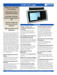
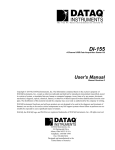
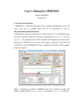
GL220 midi Logger
Built-in 4.3" WQVGA TFT
LCD Color Display
Stand-alone or PCconnected operation
10 Analog Channels
Input-to-output &
channel-to-channel
Isolation
USB PC Interface
With its color monitor and internal
memory the GL220 is a compact,
lightweight, multi-channel data logger that
provides 10 analog measurement channels,
in addition to four channels each of
discrete logic and pulse inputs. The GL220
also supports one external trigger input and
four alarm outputs. The GL220 is equipped
with a 2 GB internal flash memory to
allow the direct capture of acquired data,
and its built-in USB port may be used to
connect any standard USB flash drive for
incremental capacity. Alternatively, the
USB interface may be connected to a PC
to allow data upload in real time or from
memory, as well as remote configuration
and real time data acquisition.
Wide Voltage Measurement
Range
Each GL220 analog channel can measure
from 20 mV to 50 VFS across eleven
programmable measurement ranges.
Full Electrical Isolation Per
Channel
Each analog GL220 channel is electrically
isolated from all others and from
instrument ground to allow accurate
and safe measurements in industrial
applications where ground potential
differences are common.
Humidity Measurements
Use the GL220 to measure humidity with
an optional sensor.
Features
Voltage, Current, and
Temperature Measurements
Use the GL220 to measure voltages,
currents, 4-20 mA process currents, as well
as thermocouple-based temperatures.
Four Pulse Inputs for Speed
and Counting Measurements
The GL220 provides four discrete input
channels that can be used for counting and
rotational speed measurement applications.
Real Time and Post-recorded
Calculations
The GL220 may be programmed to calculate average value, peak value, minimum
value, rms and arithmetic operations.
Four Alarm Outputs
Program the GL220 to trigger its alarm
outputs as a function of analog input signal
level judgment, pulse judgment, or logic
pattern.
Total of Four Discrete Inputs
for Logic Measurements
Use the GL220 to measure the binary
status of any external system.
Flexible Triggering Options
The GL220 allows data capture to be
started or stopped based upon signal
level, an external event, date/time, alarm,
duration, or Boolean channel combinations.
Analog signal triggers can be programmed
based upon level and window tests: above
threshold, below threshold, inside window,
or outside window.
Flexible Power Requirements
Power the GL220 from its provided
international AC adaptor, from an optional
built-in battery pack, or from any 9 to 24
VDC source using an optional cable.
PC Connectivity and Memory
Expansion via USB Interface
Allows data transfer to the PC either in
Wide Sample Interval Selections real time or from the GL220’s memory.
Sample intervals can be programmed to be
one of sixteen values ranging from 10 ms
to one hour.
Bright TFT LCD Color Display
The focal point of the GL220 is its 4.3”
built-in WQVGA color display that
allows real time trending, data review, and
complete instrument configuration.
Engineering Units Scaling
Each GL220 channel allows up to four
break points to be programmed for accurate
scaling into meaningful units like psi,
grams, newtons, gallons per minute, etc.
Also allows complete configuration of the
GL220. Connect any standard USB Flash
Drive to the USB port for external memory
expansion.
PC Software Bundle Included
The GL220 includes a Windows
application for direct capture,
measurement, and monitoring of GL220
data. In addition to waveform and data
value capture and display, the application
can export data to an Excel file for further
analysis and report creation. The software
includes built-in help for quick reference.
DATAQ Instruments, Inc. • 241 Springside Drive • Akron, Ohio 44333 • Tel: 330-668-1444 • Email: [email protected] • www.dataq.com
GL220 Display, I/O, and Control Overview
330-668-14442
www.dataq.com
GL220 Analog Input Circuit and Measurement Ranges
Each GL220 analog input channel features electrical isolation using a photo MOS relay switching method to maintain safe
and accurate measurements in demanding industrial environments.
+
50Ω
500kΩ
0.05µF
500kΩ
0.05µF
50Ω
Channel
Switching
Relay
Voltage Measurement Ranges per Channel
Range
Maximum SPAN
Minimum SPAN
Minimum Resolution
20mV
-22.000 to +22.000mV
0.200mV
0.001mV
50mV
-55.00 to +55.00mV
0.50mV
0.01mV
100mV
-110.00 to +110.00mV
1.00mV
0.01mV
200mV
-220.00 to +220.00mV
2.00mV
0.01mV
500mV
-550.0 to +550.0mV
5.0mV
0.1mV
1V
-1.1000 to +1.1000V
0.0100V
0.0001V
2V
-2.2000 to +2.2000V
0.0200V
0.0001V
5V
-5.500 to +5.500V
0.050V
0.001V
10V
-11.000 to +11.000V
0.100V
0.001V
20V
-22.000 to +22.000V
0.200V
0.001V
50V
-55.00 to +55.00V
0.50V
0.01V
Process Current Measurement (with external 250-ohm resistor)
Range
Maximum SPAN
Minimum SPAN
Minimum Resolution
1-5 V
-5.500 to +5.500V
0.050V
0.001V
Temperature Measurement Ranges per Channel (note no RTD measurements)
Range
Maximum SPAN
Minimum SPAN
Measurement Range
K
-200 to +1370°C
J
-200 to +1100°C
T
-200 to +400°C
R
E
Minimum Resolution
0 to +1600°C
-270 to +2000°C
50°C
-200 to +900°C
B
+600 to +1920°C
S
0 to +1760°C
N
0 to +1300°C
W
0 to +2315°C
Optional Humidity Measurement Range
0.1°C
Range
Maximum SPAN
Minimum SPAN
Minimum Resolution
0 to 100%
0 to +110%
1.0%
0.1%
www.dataq.com3
330-668-1444
Typical GL220 Analog Signal Connections
Analog Input Terminal Configuration
Voltage input
DC Voltage
Thermocouple input
Compensation wire is
used if it is required.
Current input
DC current
Shunt resister
Ex: The current is converted to the voltage in
the shunt register.
For 4 to 20mA current input, installing 250
ohms (0.1%) resister for converting 1 to 5V.
+
......................................................... High -voltage terminal (terminal for high voltage signals)
-
......................................................... Low-voltage terminal (terminal for low-voltage input signals)
Item
Description
Input configuration
Isolated input, scanning
Analog voltage
20, 50, 100, 200, 500 mV/F.S.; 1, 2, 5, 10, 20, 50, V/F.S.; 1-5V
Thermocouples
K, J, E, T, R, S, B, N, W (WRe 5-26)
A/D resolution
16-bit (Effective resolution: About 1/40,000 of the +/- range)
Filter
Off, 2, 5, 10, 20, 40
Filter operation is on a moving average basis.
The average value of the set sampling count is used.
Usable Channels at Different Sampling Speeds
Sampling Speed:
Number of usable channels:
Measurement
phenomenon
Voltage:
Temperature:
10ms
20ms
50ms
100ms
1s
1
2
5
10
10
●
●
●
●
●
●
●
330-668-14444
www.dataq.com
Program the GL220 for Real-World Trigger Conditions
The GL220 can adapt to just about any trigger condition you might encounter. Data recording can be stopped or started as
a function of analog signal level, a definable alarm condition, an external event, or specific date and time. Beyond initiating a data capture cycle, the GL220 can also be programmed to set a digital output to flag an external alarm condition.
And after a trigger condition is executed you can program the GL220 to automatically rearm itself to wait for another
trigger event, or stop entirely. You can even program the GL220 to detect and alarm on a thermocouple burnout condition.
Here’s a summary of the GL220’s trigger and alarm features:
GL220 Trigger and Alarm Overview
Setting
Selections Available
Off, Level, Alarm, External Input, Time, Day, Duration
[Level]
Start
side
source
setting
Mode
Analog: Off, ↑H, ↓L, Window In, Window Out; Logic: Off, ↑H, ↓L; Pulse: Off, ↑H, ↓L, Window In, Window Out
Combination
Level OR, Level AND, Edge OR, Edge AND
Level
Set numeric value
[Alarm]
Alarm port #
1•2•3•4
[Date]
Date
From 2005.1.1 to 2035.12.31
Time
From 0:0:0 to 23:59:59
Day of week
Off or On setting for each of Sunday through Saturday
Time
From 0:0:0 to 23:59:59
[Weekly]
[Time]
[Level]
Stop
side
source
setting
From 0:0:1 to 9999:59:59
Mode
Analog: Off, ↑H, ↓L, Window In, Window Out; Logic: Off, ↑H, ↓L; Pulse: Off, ↑H, ↓L, Window In, Window Out
Combination
Level OR, Level AND, Edge OR, Edge AND
Level
Set numeric value
[Alarm]
Alarm port #
1•2•3•4
[Date]
Date
From 2005.1.1 to 2035.12.31
Time
From 0:0:0 to 23:59:59
Day of week
Off or On setting for each of Sunday through Saturday
Time
From 0:0:0 to 23:59:59
[Weekly]
[Time]
From 0:0:1 to 9999:59:59
Repeated capturing
Alarm
level
settings
Off, On
Mode
Analog: Off, ↑H, ↓L, Window In, Window Out; Logic: Off, ↑H, ↓L; Pulse: Off, ↑H, ↓L, Window In, Window Out
Level
Set numeric value
Output
1•2•3•4
Detection Method
Level, Edge
Alarm Hold
On, Off
Send Burnout Alarm
On, Off
GL220 Trigger Modes
Above Threshold
Below Threshold
Measurement starts (alarm generated)
Measurement starts (alarm generated)
CH1
CH1
Inside Window
Outside Window
Measurement starts (alarm generated)
Measurement starts (alarm generated)
CH1
CH1
www.dataq.com5
330-668-1444
GL220 Logic, Pulse, Alarm, and External Trigger Connections
The logic alarm cable (B-513: Option) allows access to the GL220’s logic/pulse input, external trigger input, external
sampling input, and alarm signal output.
Connect the logic alarm cable (B-513: Option) to the external input/output terminal as shown below.
Logic/Pulse Specifications
Trigger input/external sampling input specifications
Item
Description
Item
Description
Number of input channels
4
Number of input channels
1
Input voltage range
0 to +24V max. (single-ended
ground input)
Input voltage range
0 to +24V max. (single-ended
ground input)
Threshold level
Approx. +2.5V
Threshold level
Approx. +2.5V
Hysteresis
Approx. 0.5 V (+2.5 to +3 V)
Hysteresis
Approx. 0.5 V (+2.5 to +3 V)
Alarm output specifications and Circuit
Item
Description
Number of output channels 4
Output format
Open collector output
+5V, pull-up resistance 10
KΩ
330-668-14446
www.dataq.com
External Memory and USB Connections, and an Optional Battery Pack
The GL220 provides the added benefit of PC connectivity to its USB port, which doubles as a method to expand the GL220’s internal 2 GB memory using standard USB flash memory. Flash drives may be hot-swapped as they fill to accommodate long term measurements. When the USB port is connected to a PC you can upload measurement protocols to the
GL220, monitor acquired data in real time, or download previously acquired data. Up to ten GL220’s may be simultaneously connected to one PC through USB hubs (there is no synchronization between units). Finally, an optional battery
pack may be added to the GL220 to allow power-independent data recording whenever and wherever it’s required.
USB Flash Drive Memory Expansion
USB-to-PC Interface Connection
Optional B-517 Battery Pack
www.dataq.com7
330-668-1444
GL220 Display Quick-look
The GL220’s keyboard and display are key components you’ll use for any typical data recording session. The display is
a full color TFT LCD (thin-film transistor liquid crystal display), the same technology used in modern flat-panel televisions. The display measures 4.3 inches diagonally, and offers 480 × 272 pixels of bright, clear, high contrast resolution.
The GL220’s keyboard allows full access to the instrument’s menu system as viewed through its display. Navigation is
straightforward and intuitive using the keyboard’s navigation and ENTER keys that form the center of the array. Other
keys support special operations that are clearly annotated.
GL220 Display Close-up and Modes
Display Close-up
Keyboard Close-up
MONITOR
Digital Screen
Trigger Settings
AMP Settings
Alarm Settings
330-668-14448
www.dataq.com
GL220 “Ring Capture” and External Sampling
The GL220’s ring capture feature provides a continuous recording solution for measurement situations where events need
to be recorded, but their occurrence is separated by long and unpredictable time intervals. Ring capture employs a pingpong memory approach to data recording with a definable memory length, which may be adjusted to ensure that a recorded event is retained long enough for manual intervention to stop recording and allow data retrieval. External sampling
allows the GL220 to be marginally synchronized to an external trigger signal.
The Ring Capture Concept
Start capturing data
Captured data is saved into File 1.
When the specified number of data points are saved into File 1, the captured data is saved into File 2.
The number of data points to capture is specified in the “Ring Capture Points” menu.
When the specified number of data points are saved into File 2, the captured data is saved into File 3.
File1 is deleted at this point.
When the specified number of data points are saved into File 3,
the captured data is saved into File 4.
File2 is deleted at this point.
When the specified number of data points are saved into File 4,
the captured data is saved into File 5.
File3 is deleted at this point.
Repeat action.
Stop capturing data
File1
File2
File3
File4
File5
When capturing is stopped at the STOP POINT above, File4 and File 5 remain.
These files are consolidated into one file and it is saved. The “ring capture” is complete.
File4
File5
Filexx・・・: Saved
External Sampling
www.dataq.com9
330-668-1444
GL220 Included and Optional Accessories
Included PC Software
Item
Description
Compatible OS
Windows XP/Vista/Windows 7
Functions
Main unit control, realtime data capture, data conversion, data replay
Main unit settings
AMP settings, Data Capture settings,Trigger Alarm settings, Report settings, Other settings
Captured data
Realtime data (CSV, Binary); Internal memory (CSV, Binary); USB memory (CSV, Binary)
Display
Analog waveforms, logic waveforms, pulse waveforms, digital values
Display modes
Y-T View, Digital View, Report View, X-Y View between Cursors (only during replay)
File conversion
Between cursors, All data, Thinning function
Monitor functions
Alarm monitor enables sending of email to the specified address
Report function
Automatic creation of daily or monthly files
Maximum/Minimum
The maximum, minimum and current values are displayed during measurement
Included Accessories
Item
Description
Quick Start Guide
GL220-UM-8 xx
CD-ROM
GL220-CDM 0 x M (User’s Manual, Application software)
AC cable/AC adapter
100 to 240 VAC, 50/60 Hz, one set of region-specific power cables
Optional Accessories
Item
Option No.
Description
Battery pack
B-517
7.2V/2200mAh
Logic Alarm Cable
B-513
Bare tips (2m)
DC power cable
B-514
Bare tips (2 m)
Humidity sensor
B-530
3m, with dedicated power connector
Carrying Case
B-536
Durable carrying case designed specifically for the GL220
Optional Battery Pack model B-517
Item
Description
Capacity
7.4V/2200mAh 17Wh
Battery type
Lithium secondary battery
When using the LCD display: approx. 5 hours; When using the screensaver: approx. 6 hours
Note: When capturing to internal memory at 1 s, sampling, using new battery packs at +25°C environment.
Running time
Note: Running time depends on the operating environment, the amount of charge left in the battery and connecting USB
memory.
Charging method
Mount in the main unit, or use a separate battery charger
Time required for charging Main unit: approx. 4 hours
Switchover in the case of Because the battery is used together with the AC adapter, the power supply will be switched automatically to the battery in
power failure
the event of a power failure. Note: The AC adapter is the primary power source.
Operating environment
Running on battery: 0 to 40°C, Battery being charged: 15 to 35°C
When the battery is running low, measured data is saved and the file is closed automatically (during internal memory and
Other functions
USB memory capture). The remaining battery power is displayed.
Optional Humidity Sensor model B-530
Item
Description
Alowable temperature range
-25 to 80°C
Allowable Humidity Range
0 to 100%
Relative humidity measurement accuracy
Response time
Sensor output
Sensor power source
Power consumption
External dimensions
Cable length
±3% RH (5 to 98% RH at 25°C)
15 s (90% response when membrane filter installed)
0 to 1 VDC
5 to 16 VDC
approx. 4mA
14mm × 80 mm (excluding cable)
3m
330-668-144410www.dataq.com
GL220 External Dimensions
91.6
102
15
16.5
2
40
194
162
16.1
67
M4 L5 insert screw
Dimension precision: Error ± 5 mm
Unit: mm
www.dataq.com11
330-668-1444
GL220 Specifications
Data save functions:
Overall Specifications
Number of analog inputs:
External input/output:
10 channels
Trigger input or external sampling pulse/logic input
4 channels or pulse input 4 channels, alarm output
4 channels
PC interface: USB (Full speed) standard
Internal memory devices: Approx. 2 GB internal memory
USB memory slot (Full speed supported) standard
Data backup functions: Setup conditions: EEPROM; Clock: lithium battery
Clock accuracy: ± 0.002% (approx. 50 seconds per month)
(ambient temperature 23°C)
Operating Environment: 0 to 45°C, 5 to 85%RH (0 to 40°C when operated
in batteries/15 to 35°C when battery is charging)
Withstand voltage: Between each input channel and GND: 1 minute at
350 Vp-p; Between each input channels: 1 minute
at 350 Vp-p
Power supply: AC adapter: 100 to 240 VAC, 50/60 Hz
DC input: 8.5 to 24 VDC (max. 26.4 V)
Battery pack (option): 7.4 VDC (2200 mAh)
Power Consumption: AC Power consumption (when AC adapter is
used)
Condition
LCD on
Screensaver on
Normal
Consumption
12 VA
11 VA
Consumption during
battery recharge
29 VA
28 VA
DC Power consumption
DC
Voltage
+24V
+24V
+12V
+12V
+8.5V
+8.5V
External Dimensions:
Weight:
Vibration-tested conditions:
Condition
LCD on
Screensaver on
LCD on
Screensaver on
LCD on
Screensaver on
Normal
Consumption during
Consumption
battery recharge
0.18 A
0.6 A
0.15 A
0.57 A
0.31 A
Can’t Recharge
0.26 A
Can’t Recharge
0.45 A
Can’t Recharge
0.37 A
Can’t Recharge
194 × 117 × 42 mm
520g (excluding AC adapter and battery)
Equivalent to automobile parts Type 1 Category A
classification
Capture to internal memory; Capture to USB
memory; The setup data can be saved (Main or
USB memory); Copy of data screen can be saved
(Main or USB memory)
Ring capture: Function: ON, OFF; Number of recording points:
1000 to 2000000 (When ring capture is ON, the
memory space that can be used for capture is onethird of the free space or less.)
Calculation between Calculation type : +, -. ×, ÷; Input target : Analog
Channels: channels 1 through 10
Statistical Calculation: Types of operation : Average value, peak value, max/
min value, RMS; Number of operations : 2 max. can
be set simultaneously; Calculation method : Realtime
calculation and calculation between cursors (during
replay) (Realtime calculation results are displayed in
the Digital + Calculation Display screen.)
Search functions: Function: Search the captured data for the required
number of points; Search type: Channel Pulse,
Logic, Level, Alarm search
Annotation input func- Function: A comment can be input for each chantion: nel; Inputtable characters: Alphanumerics; Number
of characters: 31 (Displayed up to 18 characters in
the Waveform + Digital screen or 14 characters in
the Digital + Calculation Display screen)
Analog Channel Specifications
Number of inputs:
Input terminal type:
Input method:
Scan speed
Measurement Ranges
Voltage:
Temperature:
Humidity:
Measurement accuracy*
Voltage:
Temperature:
PC Interface
Interface types: USB (full speed)
Functions: Data transfer to PC (real time, memory)
PC control of the GL220
USB functions: USB drive mode:Transfers and deletes file from
internal memory
Real time data transfer speed: 10 ms/1ch maximum
Overall Functional Specifications
Display Screen: Waveform + Digital screen, All Waveform screen,
Digital + Calculation Display screen, Expanded
digital screen. (Can be switched using the dedicated key (toggle operation). For the Expanded
Digital screen, the number of channels and the
display channel must be specified.)
Sampling interval*: 10, 20, 50, 100, 125, 200, 250, 500 ms; 1, 2, 5, 10,
20, 30 s; 1, 2, 5, 10, 20, 30 min; 1 h, External
(* 50 ms and below can be selected according to
input settings and number of measured channels.)
Waveform expansion/ Time axis: 1, 2, 5, 10, 20, 30 sec/Div
contraction
1, 2, 5, 10, 20, 30 min/Div
1, 2, 5, 10, 12, 24 h/Div
Voltage axis: variable span
Scaling function: 4 points can be set for each channel.
Functions during cap- Double-screen display; Exchange of USB memory;
ture: Saving of data between cursors
Reference contact compensation accuracy:
A/D converter:
Temperature coefficient:
Input resistance:
Allowable signal source
resistance:
Maximum permissible
input voltage:
10
M3 screw type terminal
Photo MOS relay scanning system; all channels
isolated, balanced input
10 ms/1 ch maximum
20, 50, 100, 200, 500 mV; 1, 2, 5, 10, 20, 50 V; 1-5
F.S.
Thermocouples: K, J, E, T, R, S, B, N, W
0 to 100% (Voltage 0V to 1V scaling conversion)
0.1% of Full Scale
Measurement Temperature
Range (°C)
0 ≤ Ts ≤ 100
100 < Ts ≤ 300
R/S
R: 300 < Ts ≤ 1600
S: 300 < Ts ≤ 1760
400 ≤ Ts ≤ 600
B
600 ≤ Ts ≤ 1820
-200 ≤ Ts ≤ -100
K
-100 < Ts ≤ 1370
-200 ≤ Ts ≤ -100
E
-100 < Ts ≤ 800
-200 ≤ Ts ≤ -100
T
-100 < Ts ≤ 400
-200 ≤ Ts ≤ -100
J
-100 < Ts ≤ 100
100 < Ts ≤ 1100
N
0 ≤ Ts ≤ 1300
W
0 ≤ Ts ≤ 2000
Reference contact compensation accuracy
TC
Measurement
Accuracy (°C)
±5.2
±3.0
±(0.05% of rdg +2.0)
±(0.05% of rdg +2.0)
±3.5
±(0.05% of rdg +2.0)
±(0.05% of rdg +2.0)
±(0.05% of rdg +1.0)
±(0.05% of rdg +2.0)
±(0.05% of rdg +1.0)
±(0.1% of rdg +1.5)
±(0.1% of rdg +0.5)
±2.7
±1.7
±(0.05% of rdg +1.0)
±(0.1% of rdg +1.0)
±(0.1% of rdg +1.5)
±0.5
Internal/External switching
Method :ΔΣ method; Resolution :16-bit (Effective
resolution: About 1/40,000 of the +/- range)
Gain : 0.01% of F.S./°C; Zero : 0.02% of F.S./°C
(Occurs when sampling speed is 10, 20, or 50 ms.)
1 MΩ ±5%
Within 300Ω
Between +/– input terminals :60 Vp-p
Between input terminal/input terminal :60 Vp-p
Between input terminal/GND :60 Vp-p
330-668-144412www.dataq.com
GL220 Specifications (continued)
Withstand voltage:
Insulation resistance:
Common mode rejection
ratio:
Noise:
Filter:
Between input terminal/input terminal :1 minute at
350 Vp-p; Between input terminal/GND :1 minute
at 350 Vp-p
At least 50 MΩ (at 500 VDC)
At least 90 dB (50/60 Hz; signal source 300 Ω or
less)
At least 48 dB (with +/– terminals shorted)
Off, 2, 5, 10, 20, 40; Filter operation is on a
moving average basis. The average value of the
set sampling count is used. If the sample interval
exceeds 5 seconds, the average value of data
obtained in a sub-sample (5 seconds) is used.
* 23°C ±3°C when 30 minutes have elapsed after the power was switched on (filter On (10),
1 s sampling, GND connected).
Alarm judgment modes:
Discrete I/O Specifications
Input/Output types:
Input specifications:
Integral TFT LCD Display
Display:
4.3-inch TFT color LCD (WQVGA: 480 × 272
dots)
Displayed languages: English, French, Japanese, German, Chinese,
Korean
Backlight life: 20000 hr (when brightness is down to 50%),
depends on operation environment
Backlight: Screensaver function (10, 30 sec., 1, 2, 5, 10, 30, 60
min.)
Internal Memory Devices
Memory capacity: Internal memory: Approx. 2GB Flash Memory
USB memory: Unlimited (However, one file must
be 2GB at the maximum.)
Memory contents: Setup conditions, measured data, screen copy
Trigger Function Specifications
Repeat trigger: Off, On
Trigger types: Start: Data capture starts when a trigger is generated.
Stop: Data capture stops when a trigger is generated.
Trigger conditions: Start: Off, Level, Alarm, External, Time, Date,
Weekly
Stop: Off, Level, Alarm, External, Time, Date,
Weekly
Level trigger judgment Combination : Level OR, Level AND, Edge OR,
modes: Edge AND
Analog channel judgment mode : H (↑), L (↓),
Window In, Window Out
Logic channel judgment mode : H (↑), L (↓)
Pulse channel judgment mode : H (↑), L (↓), Window In, Window Out
Detection method : Level, Edge
Analog channel judgment mode : H (↑), L (↓),
Window In, Window Out
Logic channel judgment mode : H (↑), L (↓)
Pulse channel judgment mode : H (↑), L (↓), Window In, Window Out
Alarm output
specifications:
Pulse input
Revolutions mode
(engines, etc):
Counts mode
(electric meters, etc.):
Inst. mode:
Maximum number of
pulse inputs:
Trigger input (1 ch) or External sampling input
(1 ch); Logic input (4 ch) or Pulse input (4 ch);
Alarm output (4 ch); Switch between Logic and
Pulse; Switch between Trigger and External
sampling; The logic alarm cable B-513 (option) is
required to use the external I/O function.
Input voltage range : 0 to +24V (single-ended
ground input); Input signal : No-voltage contact
(a-contact, b-contact, NO, NC), Open collector,
Voltage input; Input threshold voltage : Approx.
+2.5 V; Hysteresis : Approx. 0.5 V (+2.5 to + 3 V)
Output format: Open collector output (5 V, pull-up
resistance 10 KΩ)
<Maximum ratings of output transistor>
• Collector-GND voltage : 30 V
• Collector current : 0.5 A
• Collector dissipation : 0.2 W
Function: Counts the number of pulses per second;
enables them to be converted to rpms.
Spans: 50, 500, 5000, 50 k, 500 k, 5 M, 50 M, 500
M PRM/F.S.
Function:Displays a count of the number of
pulses for each sampling interval from the start of
measurement.
Spans: 50, 500, 5000, 50 k, 500 k, 5 M, 50 M, 500
M C/F.S.
Function:Counts the number of pulses for each
sampling interval. Resets the count value after
each sampling interval.
Spans: 50, 500, 5000, 50 k, 500 k, 5 M, 50 M, 500
M C/F.S.
Maximum input frequency : 50kHz
Maximum number of count : 50kC/sampling (16bit counter)
Ordering Guide
Description
Order No.
Description
Order No.
Battery pack
7.2V/2200mAh lithium battery pack.
GL220
Compact, lightweight, multi-channel data logger
with 10 analog measurement channels, 20mV to
50V Full Scale measurement range, and 2 GB
internal flash memory.
DC Power Cable
GL220
2-meter DC power cable, bare tips.
Humidity Sensor
3-meter with dedicated power connector.
Logic/Alarm Cable
2-meter logic/alarm cable, bare tips.
DATAQ Instruments, Inc.
241 Springside Drive
Akron, Ohio 44333
Phone: 330-668-1444
Fax: 330-666-5434
Data Acquisition Product Links
(click on text to jump to page)
Data Acquisition | Data Logger | Chart Recorder | Thermocouple | Oscilloscope
DATAQ, the DATAQ logo and WinDaq are registered trademarks of DATAQ Instruments, Inc. All rights reserved. Copyright © 2013 DATAQ Instruments, Inc.
The information on this data sheet is subject to change without notice.
B-517
B-514
B-530
B-513