1
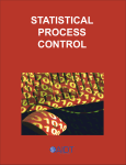
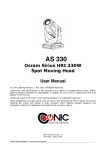
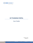
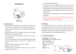
4312775.51
FCC Test report for LED Tube
Models ZY-T8-31W2400 series
Guangzhou, date of issue: 2013-09-06
Author Ryan Liang
By order of James Industry Group Co., Ltd at Hong Kong, China
Author :
Ryan Liang
Pages : 20 pages
Reviewed :
Tim Yan
Annex : NIL
DEKRA Testing and Certification (Shanghai) Ltd. Guangzhou Branch
Building A3, No.3 Qiyun Road, Science City, Guangzhou Hi-Tech Industrial Development Zone, Guangzhou, P.R. China
Tel +86 20 6661 2000 Fax +86 20 6661 2001 www.dekra-certification.com
Version: 3.0
- Page 2 of 20 -
CONTENTS
4312775.51
page
1
Conclusion ............................................................................................................. 3
2
2.1
2.2
2.3
Summary ............................................................................................................... 4
Applied standards .................................................................................................. 4
Reference standards .............................................................................................. 4
Overview of results ................................................................................................ 4
3
Classification .......................................................................................................... 5
4
4.1
4.2
4.3
4.4
4.5
General Information ............................................................................................... 6
Model description ................................................................................................... 6
Product Information ................................................................................................ 8
Customer Information............................................................................................. 8
Product labeling ..................................................................................................... 9
User information..................................................................................................... 9
5
5.1
5.2
5.3
5.4
Test information ................................................................................................... 10
Test facility ........................................................................................................... 10
Measurement procedure ...................................................................................... 10
Test data .............................................................................................................. 10
Environmental conditions ..................................................................................... 10
6
6.1
6.2
6.3
Conducted emissions ........................................................................................... 11
Measurement procedure ...................................................................................... 11
Measurement equipment ..................................................................................... 11
Measurement data ............................................................................................... 12
7
7.1
7.2
7.3
Radiated emissions .............................................................................................. 15
Measurement procedure ...................................................................................... 15
Measurement equipment ..................................................................................... 15
Measurement data ............................................................................................... 16
8
Test setup and arrangement ................................................................................ 18
9
Product Internal Photo ......................................................................................... 19
Version: 3.0
- Page 3 of 20 -
1
4312775.51
CONCLUSION
The device under test (DUT) as mentioned in this report complies with the stated
requirements of the FCC Part 15, Class B.
The tested system is classified as digital device Class B marked for use in a residential
environment notwithstanding use in commercial, business and industrial environments.
The conclusion and results stated in this test report are based on a non-recurrent examination
of sample(s) provided by the applicant.
The tests described in this report do not result in the right to use any approval mark as
conferred by DEKRA Testing and Certification (Shanghai) Ltd. Guangzhou Branch As far as
the tests were based on certain specifications; these are mentioned in the report.
Version: 3.0
- Page 4 of 20 -
2
4312775.51
SUMMARY
This chapter presents an overview of standards and results. Refer to the next chapters for
details of measured test results and applied test levels.
2.1
Applied standards
Standard
Year
Title
FCC part 15
2013
Federal Communications Commission (FCC) – Radio
Frequency Devices
2.2
Reference standards
Standard
ANSI C63.4
2.3
Year
Title
2009
American National Standard for Methods of Measurement
of Radio-Noise Emissions from Low-Voltage Electrical and
Electronic Equipment in the Range of 9 kHz to 40 GHz
Overview of results
Emission tests
Result
Conducted emission
PASS
Radiated emission
PASS
Version: 3.0
- Page 5 of 20 -
3
4312775.51
CLASSIFICATION
This chapter presents an overview of the applicable classification and procedure.
The following procedure has been selected to confirm the compliance of the device under test:
Verification procedure: The Device under Test (DUT) is subject to the Verification
procedure. The Verification procedure is defined in 47CFR Part 2 section 2.902 and
described in section 2.951 through 2.957 of the FCC rules.
Base on client’s declaration, the following applicable Class has been selected:
Class A : The intended user environment of the device under test is limited to
industrial environments and classified as a digital device class A.
Class B : The intended user environment of the device under tests is in commercial
and light-industrial environments and classified as a digital device class B.
For the device under test the following measurement clauses are applicable:
47CFR Part 15 Subpart B Unintentional radiators.
Section 15.107(b) Conducted emissions – Class A
Section 15.107(a) Conducted emissions – Class B
Section 15.109(b) Radiated emissions – Class A
Section 15.109(a) Radiated emissions – Class B
Version: 3.0
- Page 6 of 20 -
4
GENERAL INFORMATION
4.1
Model description
4312775.51
The apparatus as supplied for the test is LED Tube, model ZY-T8-31W2400 AIDS is intended
for residential use, the products contain electronic control circuitry but without earth
connection and no component susceptible to magnetic fields.
All models use same LED driver and same construction, the difference is the rating, the
difference list as below table 1:
Model
ZY-T8-31W2400 AIDS, ZY-T8-31W2400 AIDT
ZY-T8-31W2400 AINS, ZY-T8-31W2400 AINT
ZY-T8-31W2400 BIDS, ZY-T8-31W2400 BIDT
ZY-T8-31W2400 BINS, ZY-T8-31W2400 BINT
ZY-T8-31W2400 CIDS, ZY-T8-31W2400 CIDT
ZY-T8-31W2400 CINS, ZY-T8-31W2400 CINT
ZY-T8-31W2400 DIDS, ZY-T8-31W2400 DIDT
ZY-T8-31W2400 DINS, ZY-T8-31W2400 DINT
ZY-T8-31W1800 AIDS, ZY-T8-31W1800 AIDT
ZY-T8-31W1800 AINS, ZY-T8-31W1800 AINT
ZY-T8-31W1800 BIDS, ZY-T8-31W1800 BIDT
ZY-T8-31W1800 BINS, ZY-T8-31W1800 BINT
ZY-T8-31W1800 CIDS, ZY-T8-31W1800 CIDT
ZY-T8-31W1800 CINS, ZY-T8-31W1800 CINT
ZY-T8-31W1800 DIDS, ZY-T8-31W1800 DIDT
ZY-T8-31W1800 DINS, ZY-T8-31W1800 DINT
Rating
power
Use same
driver
31W
Use same
driver
Table 1
Hence, model ZY-T8-31W2400 AIDS was subject for full test, and the corresponding data is
representative of derivative models list in table 1 as well.
Version: 3.0
- Page 7 of 20 -
4312775.51
Figure 1 model ZY-T8-31W2400 AIDS
The Operating Modes as stated in the User Manual are on mode and off mode.
Version: 3.0
- Page 8 of 20 -
4.2
Product Information
Equipment under test
LED Tube
Trade mark
James
Tested Type
ZY-T8-31W2400 AIDS
U nominal
P rated
100Vac, 60Hz, Class II, 31W
Highest frequency used
in the device
less than 108 MHz
Representative Type
ZY-T8-31W2400 series
U nominal
P rated
Highest frequency used
in the device
4.3
4312775.51
100Vac, 60Hz, Class II, 31W
less than 108 MHz
Customer Information
Applicant /
Manufacturer
James Industry Group Co., Ltd
Contact person
Mr DENG JINSHENG
Telephone
+852-3173 3712
Telefax
+852-3173 3713
Address
Room 1205(S01), 12/F., Tai Sang Bank Bldg 130-132 DES
VOEUX RD, CENTRAL, HONGKONG
Factory
DONGGUAN ZHIYUAN LIGHTING TECHNOLOGY CO.,
LTD
Contact person
Mr DENG JINSHENG
Telephone
+86-13500093572
Telefax
+86-769-22991702
Address
ChuangYe Industry Park, XinXiBian, LiXinNiuShan,
DongCheng District, DongGuan City, GuangDong Province,
China 523128
Version: 3.0
- Page 9 of 20 -
4.4
4312775.51
Product labeling
According to section 15.19, the DUT shall have the following statement labeled to its housing
on a conspicuous location:
“This device complies with Part 15 of the FCC Rules. Operation is subject to
the following two conditions: (1) This device may not cause harmful
interference, and (2) this device must accept any interference received,
including interference that may cause undesired operation”.
4.5
User information
The user- or instruction manual shall:
Caution the user that changes or modifications not expressly approved by the responsible
party for compliance could void the user’s authority to operate the equipment.
Inform the user about special RF emission protection measures, which are delivered with the
product, for example shielded cables.
Contain the following statement in case of a Class B digital device:
“This equipment has been tested and found to comply with the limits for a Class B digital
device, pursuant to part 15 of the FCC rules. These limits are designed to provide reasonable
protection against harmful interference in a residential installation. This equipment generates,
uses and can radiate radio frequency energy and, if not installed and used in accordance with
the instructions, may cause harmful interference to radio communications. However, there is
no guarantee that interference will not occur in a particular installation. If this equipment does
cause harmful interference to radio or television reception, which can be determined by
turning the equipment off and on, the user is encouraged to try to correct the interference by
one or more of the following measures:
- Reorient or relocate the receiving antenna
- Increase the separation between the equipment and the receiver
- Connect the equipment into an outlet on a circuit different from that to which the receiver is
connected
- Consult the dealer or an experienced radio/TV technician for help “
Version: 3.0
- Page 10 of 20 -
5
TEST INFORMATION
5.1
Test facility
4312775.51
The FCC has per public notice declared these measurement facilities to be reviewed and to
be in compliance with the requirements of Section 2.948 of the FCC Rules.
5.2
Measurement procedure
The DUT was configured for testing in a typical user configuration. The maximum test
configuration was put to the tests. The DUT was tested as complete system.
5.3
Test data
Location
DEKRA Testing and Certification (Shanghai) Ltd.
Guangzhou Branch
Address
Building A3, No.3 Qiyun Road, Science City, Guangzhou
Hi-Tech Industrial Development Zone, Guangzhou, P.R.
China
Date
2013-07-02 to 2013-08-09
Supervised by
Ryan Liang
5.4
Environmental conditions
Tests have been performed in a controlled laboratory environment, where the environmental
conditions are maintained within the applicable ranges.
Ambient temperature
15 °C – 35 °C
Relative Humidity air
30% - 60%
Version: 3.0
- Page 11 of 20 -
6
CONDUCTED EMISSIONS
6.1
Measurement procedure
4312775.51
In accordance with section 15.107 the conducted radio frequency disturbance voltages
between each of the power lines (live and neutral) and the ground terminal are determined
over the frequency range from 150 kHz to 30 MHz.
The test set-up is in accordance with the requirements of ANSI C63.4.
The AC power line conducted emission measurements were performed at the line voltage of
120 Vac and at the power frequency of 60 Hz.
The initial step in collecting conducted data is a peak scan measurement over the frequency
range of interest. Significant peaks are marked, and these peaks are re-measured using a
quasi peak and average detector. This procedure is implemented in the utilized test receiver
by the incorporated EMI firmware. The test receiver used also meets the requirement as
mentioned in section 15.35 “measurement detector functions and bandwidths”. The test
receiver employs a CISPR quasi-peak detector function with a bandwidth of 9-10 kHz.
6.2
Measurement equipment
Instrumentation
Model
Serial no.
Cal interval
EMI receiver
R&S
ESCI
Annual
LISN
R&S
ENV216
Annual
CABLE
R&S
3M
Annual
Shielded room
Feite Electronic
--
Annual
Version: 3.0
- Page 12 of 20 -
6.3
4312775.51
Measurement data
Limits
47CFR subpart B clause 15.107 (a) (Class B)
Standard
Frequency [MHz]
Limit QP [dB(µV)]
–
Limit AV [dB(µV)]
0,15
– 0,50
66
56 *)
56
0,50
– 5,0
56
46
0,50
– 30,0
60
50
-
46 *)
*) Limits decreasing linearly with the logarithm of the frequency
Port
AC mains
Test method
LISN
Test-mode
On mode
Results
Live
Att 10 dB AUTO
dBµV
90
1 MHz
RBW
9 kHz
MT
1 s
PREAMP ON
10 MHz
80
1 PK
MAXH
2 AV
MAXH
70
FCCBQ
TDS
60
FCCBA
50
40
6DB
DC
30
20
10
0
-10
150 kHz
30 MHz
Version: 3.0
- Page 13 of 20 -
Trace1:
4312775.51
EDIT PEAK LIST (Final Measurement Results)
FCCBQ
Trace2:
FCCBA
Trace3:
---
TRACE
FREQUENCY
LEVEL dBµV
DELTA LIMIT dB
1
Quasi Peak
150 kHz
62.33
-3.66
2
Average
206 kHz
32.56
-20.79
2
Average
262 kHz
28.09
-23.27
1
Quasi Peak
270 kHz
39.73
-21.38
1
Quasi Peak
1.99 MHz
41.46
-14.53
2
Average
1.994 MHz
28.18
-17.81
1
Quasi Peak
2.754 MHz
37.36
-18.63
2
Average
3.266 MHz
27.79
-18.21
1
Quasi Peak
4.814 MHz
43.16
-12.83
2
Average
4.934 MHz
30.30
-15.69
2
Average
6.858 MHz
30.85
-19.14
1
Quasi Peak
7.366 MHz
35.60
-24.40
1
Quasi Peak
10.654 MHz
36.04
-23.96
2
Average
29.61 MHz
28.48
-21.51
1
Quasi Peak
29.938 MHz
37.69
-22.30
No other significant emissions were measured at the frequency range of interest employing
both the QP and AV detectors.
Neutral
Att 10 dB AUTO
dBµV
90
1 MHz
RBW
9 kHz
MT
1 s
PREAMP ON
10 MHz
80
1 PK
MAXH
2 AV
MAXH
70
FCCBQ
TDS
60
FCCBA
50
40
6DB
DC
30
20
10
0
-10
150 kHz
30 MHz
Version: 3.0
- Page 14 of 20 -
Trace1:
4312775.51
EDIT PEAK LIST (Final Measurement Results)
FCCBQ
Trace2:
FCCBA
Trace3:
---
TRACE
FREQUENCY
LEVEL dBµV
DELTA LIMIT dB
1
Quasi Peak
150 kHz
62.34
-3.65
2
Average
194 kHz
39.43
-14.43
1
Quasi Peak
258 kHz
42.05
-19.43
1
Quasi Peak
1.238 MHz
33.17
-22.82
1
Quasi Peak
1.994 MHz
41.65
-14.34
2
Average
1.998 MHz
28.14
-17.86
1
Quasi Peak
2.558 MHz
36.41
-19.59
2
Average
2.634 MHz
29.38
-16.61
2
Average
4.69 MHz
29.98
-16.01
1
Quasi Peak
4.814 MHz
38.90
-17.09
2
Average
6.682 MHz
30.13
-19.86
1
Quasi Peak
6.746 MHz
41.50
-18.49
1
Quasi Peak
29.058 MHz
36.57
-23.42
2
Average
29.774 MHz
28.43
-21.56
No other significant emissions were measured at the frequency range of interest employing
both the QP and AV detectors.
Refer to chapter 8 for the test set-up.
Conclusion:
PASS
Version: 3.0
- Page 15 of 20 -
7
RADIATED EMISSIONS
7.1
Measurement procedure
4312775.51
In accordance with section 15.109.a the field strength levels of radiated emissions from this
digital device class B at a measurement distance of 3 meters were determined.
If the highest internal frequency used in the DUT is less than 108 MHz, then the frequency
range of interest shall be measured to 1 GHz. The measurements are conducted in
accordance with the methodology as described in ANSI C63.4, as required by sections 15.31
and 15.33 of 47CFR.
Below or equal to 1 GHz, preliminary radiation measurements are performed in a semi
anechoic room at a 3 meter measurement distance. The measurement receiver calculates the
resulting field strength using the correction factors for cable loss and antenna. The final
measurements are performed in the semi anechoic room at a 3 meter measurement distance
too. At those frequencies where relevant significant levels were detected during the pre-scan
the actual field strength level is measured using the CISPR quasi-peak detector with
bandwidth of 120 kHz.
The highest levels measured with horizontal or vertical polarization are mentioned on the next
page.
7.2
Measurement equipment
Instrumentation
Model
Serial no.
Cal interval
EMI receiver
R&S
ESCI
Annual
Antenna
(30MHz-3GHz)
SCHWARZBECK
VULB9163
CABLE
SCHWARZBECK
10M
Annual
Chamber
ETS.LINDGREN
9*6*6
Annual
Annual
Version: 3.0
- Page 16 of 20 -
7.3
4312775.51
Measurement data
Limits
Standard
47CFR subpart B clause 15.109 (a) (Class B)
Measuring distance
3 meters
Frequency [MHz]
QP [dB(µV/m)]
microvolts/meter
30 – 88
40,0
100
88 – 216
43,5
150
216 – 960
46,0
200
960– 1000
53,9
500
Port
Enclosure with cabling
Test set-up
3 m Semi-Anechoic chamber
Test mode
On mode
Results
Horizontal
Att 10 dB
dBµV
/m
1 PK
MAXH
70
100 MHz
RBW
120 kHz
MT
10 ms
PREAMP ON
1 GHz
60
TDS
50
FCC-B
40
6DB
DC
30
20
10
0
30 MHz
1 GHz
No significant emissions were recorded employing the QP detector at the frequency range of
interest (More than 20 dB below limits).
Version: 3.0
- Page 17 of 20 -
4312775.51
Vertical
Att 10 dB
dBµV
/m
1 PK
MAXH
RBW
120 kHz
MT
1 s
PREAMP ON
100 MHz
70
1 GHz
60
TDS
50
FCC-B
40
6DB
DC
30
20
10
0
30 MHz
1 GHz
Trace1:
EDIT PEAK LIST (Final Measurement Results)
FCC-B
Trace2:
---
Trace3:
---
TRACE
1
Quasi Peak
FREQUENCY
35.44 MHz
LEVEL dBµV/m
25.21
DELTA LIMIT dB
-14.78
No other significant emissions were recorded employing the QP detector at the frequency
range of interest.
Refer to chapter 8 for the test set-up.
Conclusion:
PASS
Version: 3.0
- Page 18 of 20 -
8
4312775.51
TEST SETUP AND ARRANGEMENT
The photograph shows the tested device.
Figure 2 Conducted Emission test setup
Figure 3 Radiated emission test setup
Version: 3.0
- Page 19 of 20 -
9
4312775.51
PRODUCT INTERNAL PHOTO
Internal view
LED view
Version: 3.0
- Page 20 of 20 -
4312775.51
Driver PCB View
Driver PCB view
Version: 3.0