1
MARC X
User’s Guide
The MARC X conforms the following standards:
EN 55022: 1998 + A1: 2000 + A2: 2003; class A
EN 55024: 1998 + A1: 2000 + A2: 2003; class A
In order for an installation of this product maintain compliance with the limits of a class
A device, shielded audio cables must be used, not longer than 50 cm. Attention: This is
a device of the class A and can cause interference to radio or television reception
within the residential area. The user is encouraged to try to correct the interference by
suitable measures.
© March 2007, v2.2 MARIAN.
Hardware Design by MARIAN
“SyncBus” developed by MARIAN
All rights reserved. No part of this User's Guide may be reproduced or transmitted in any form or by any
means, electronically or mechanical, including photocopy, translation, recording, or any information
storage and retrieval system, without permission in writing from MARIAN.
All trademarks are the property of the respective owners.
MARIAN is not liable for any damage to the software, hardware and data and costs resulting from it,
which are caused by improper handling or installation of the hardware.
Technical changes are reserved.
Table of Contents
1.
Features
3
2.
Scope of Supply
4
3.
System Requirements
4
4.
Ports
5
4.1.
4.1.1.
4.1.2.
4.1.3.
4.2.
4.3.
4.4.
MARC X PCI Card
Audio Ports
SyncBus Port
Ports for Extender Cards
MIDI/Wordclock Extender Card "MWX"
Analog I/O Extender Card "ANX"
AES/EBU Extender Card “DGX”
5
5
6
6
7
8
8
5.
Hardware Installation
8
6.
Driver Installation
10
6.1.
6.2.
6.3.
6.4.
6.5.
6.6.
6.7.
About MME, DirectX, WDM-Audio, ASIO and GSIF
Installation on Windows 95 (Release 950 and 95a)
Installation on Windows 95 (Release 95b and 95c)
Installation on Windows 98
Installation on Windows ME
Installation on Windows 2000
Installation on Windows XP
10
11
11
12
12
13
13
7.
MARC X Manager
14
7.1.
7.1.1.
7.1.2.
7.1.2.1.
7.1.2.2.
7.1.2.3.
7.1.3.
7.1.3.1.
7.1.3.2.
7.1.3.3.
Audio Settings
Operating the Control Elements
Mixer
Input and Playback Channels
Master Section
Configuring the View
Controlling the Outputs
Output Channels
Optical Output
Configuring the View
14
15
16
17
18
19
19
20
21
21
7.2.
7.2.1.
7.2.2.
7.2.3.
7.2.4.
7.2.5.
7.2.6.
7.2.7.
7.2.7.1.
7.2.7.2.
7.2.8.
7.2.8.1.
7.2.8.2.
7.2.8.3.
7.2.9.
7.2.9.1.
7.2.9.2.
Operating Mode, Clock, MIDI and other Settings
Operating Modes
Clock Settings
Internal Clock
Wordclock Output
Start/Stop Synchronization
Clock and Sample Rate Conflicts
Setting up the driver interfaces in Windows™ 95/98/ME
Section "Direct Sound"
Section “GigaSampler/GigaStudio”
Setting up the driver interfaces in Windows™ 2000/XP
MME and DirectSound
Section “Classic MME Drivers”
Section “GigaSampler/GigaStudio”
MIDI Settings
Section "Command Filters"
Section "System Data Filters"
22
22
23
25
25
26
27
28
28
29
30
30
31
31
32
33
34
8.
ASIO Settings
35
9.
Software Samplers and Synthesizers
37
10.
Technical Data
38
11.
Service and Support
39
Welcome
thank you very much for your decision to purchase one of the products
from the MARC product series.
Please consider taking some time to study this guide. Besides
traditional installation and operation instructions it contains information,
that will make the handling with the MARC X easier for you.
We wish you lots of fun and success in working with the MARC X.
1.
Features
Your MARC X provides special characteristics. In the following you will
get a short overview:
•
•
•
•
•
•
•
•
•
•
•
Stereo analog I/O, 24 bit/96 kHz
Stereo digital I/O S/PDIF, 24 bit/96 kHz
8-channel digital I/O ADAT, 24 bit/48 kHz
Port for an internal digital audio CD/DVD drive
Port for an internal analog audio CD/DVD drive
2 MIDI I/Os
Wordclock I/O, Superclock I/O
32-channel DSP mixer, hardware-based, latency-free
Latency-free and flexible monitoring
DAT marker support
MARIAN SyncBus for synchronization with other MARIAN sound
systems
• Multiple card support (up to 4 cards can be installed)
The analog I/O extender card "ANX" (not included in the scope of
supply – separately available as accessory) further provides the
following characteristic:
• 2 additional stereo analog I/Os, 24 bit/96 kHz
The Digital I/O extender card "DGX" (not included in the scope of
supply – separately available as accessory) provides the following
characteristic:
• 2 AES/EBU Inputs and Outputs (4 channels)
• 2 Input Sample Rate Converter
3
2.
Scope of Supply
First of all, please check, whether you received the following
components undamaged and complete.
•
•
•
•
MARC X PCI card
Extender card for MIDI and Wordclock “MWX”
Ribbon cable for internal connection of “MWX” with the MARC X
Cable for connecting the digital audio signal of an internal digital
audio CD/DVD drive
• MIDI cable adapter
• User’s Guide
• CD-ROM incl. drivers
If you have additionally purchased the analog I/O extender card “ANX”,
the following components are supplied:
• Analog I/O extender card "ANX"
• Ribbon cable for the internal connection of the "ANX" and MARC X
• Power cable for connecting the "ANX" to the internal power supply of
the PC
If you have additionally purchased the AES/EBU I/O extender card
“DGX”, the following components are supplied:
•
•
•
•
•
•
3.
DGX extender
XLR breakout cable with 2 AES/EBU connectors
Ribbon cable for the internal connection of the "DGX" and MARC X
Power connector
Driver CD
DGX Manual
System Requirements
In order to be able to operate the MARC X, your PC should meet the
following requirements:
•
•
•
•
•
AT compatible PC with a spare PCI slot
Pentium or AMD processor with 350 MHz or higher
Windows™ 95/98/ME/2000/XP
Microsoft DirectX 9
For extender cards "MWX", “ANX” and “DGX”:
- a spare slot in the PC housing – PCI or ISA slot is not required
• For extender card “DGX”: Windows™ 2000/XP
Please note, that the audio software you use may ask for different
requirements.
4
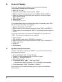
4.
Ports
4.1.
MARC X PCI Card
The ports of the MARC X.
4.1.1.
Audio Ports
Analog devices are connected to the MARC X using ¼’’ TRS jacks.
Please exclusively use high-quality and shielded cables in order to
achieve maximum audio quality.
You can connect additional analog devices using the optional analog
I/O extender card "ANX".
For connecting S/PDIF devices, you can use electrical (RCA) as well
as optical jacks (TOSLINK).
ADAT devices are connected using optical ports (TOSLINK).
If you want to use optical digital ports, you need optical connection
cables, which you can purchase at specialist shops.
For the processing of the audio signal of your CD/DVD-ROM drive, you
can either use an analog input or an electric digital input. Basically, you
should prefer using a digital CD input, because this kind of connection
offers optimum audio quality. For information of which ports are
provided by your CD/DVD-ROM drive, please refer to the appropriate
manual.
5
4.1.2.
SyncBus Port
If you use several MARC cards or other cards developed by MARIAN,
you can connect the SyncBus ports of the individual cards using a
cable. This SyncBus cable is available as accessory. If you want to
order one, please get in touch with our Sales Department (see
attachment).
The SyncBus of your MARC X has two tasks: on one side it
synchronizes the sample rate and ensures that several cards run
sample-accurately and synchronously when they are operated
concurrently. On the other side it takes care of the synchronous starting
and stopping of several internal audio devices. For details on the
settings see chapters 7.2.2 and 7.2.5.
4.1.3.
Ports for Extender Cards
The MARC X further provides a port for the MIDI/Wordclock extender
card "MWX" and a port for the optional analog I/O extender card "ANX"
and the optional AES/EBU extender card “DGX”. “ANX” and “DGX” can
not be operated simultaneously.
6
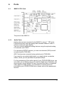
4.2.
MIDI/Wordclock Extender Card "MWX"
The picture on the left shows
all ports of the "MWX".
Using the Wordclock input
you can synchronize the
MARC X in a Wordclock
environment. If the extender is
connected at the end of the
Wordclock bus, then the
Wordclock input of the
extender needs to be
terminated. This is assured by
setting the jumpers on the
pins 2-3 of the jumper block. If the Wordclock termination is not
required, then please set the jumpers on the pins 1-2 of the jumper
block.
The Wordclock input also accepts Superclock. An according
configuration is required and is performed in the clock settings of the
driver software (see chapter "7.2.2 Clock Settings“).
For using the Wordclock input with Superclock, a termination is
urgently required to ensure a stable operation!
The Wordclock output allows the operation of the MARC X as clock
master in a Wordclock environment. It can also be configured as
Superclock output (see chapter "7.2.4 Wordclock Output“).
You can connect the supplied MIDI cable to the 9-pin D-SUB port. It
has four DIN jacks for two MIDI I/Os. Connect your external MIDI
device to these jacks.
7
4.3.
Analog I/O Extender Card "ANX"
This extender card is not included in the MARC X scope of supply. You
can order this card separately and you will receive additionally four
analog I/Os in 24 bit/96 kHz.
4.4.
AES/EBU Extender Card “DGX”
This extender card is not included in the MARC X scope of supply. You
can order this card separately and you will receive additionally two
AES/EBU I/O and Input Sample Rate Converters.
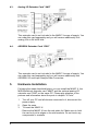
5.
Hardware Installation
Following the steps described below, you can install the MARC X, the
MIDI/Wordclock extender card "MWX" and the optional analog I/O
extender card "ANX" on the same PC. Please pay attention to the
pictures and information about the ports in chapter "4 Ports".
1.
Turn off your PC and all devices connected to it, disconnect the
power supply.
2. Open the case.
3. To insert the MARC X:
- Remove the MARC X from the anti-static foil. Make sure to hold
the card only at its edges or the slot brackets. Do not touch any
components or contacts.
8
- Insert the card carefully and rectangular into a spare PCI slot.
Ensure that the card was inserted properly into the slot.
- Screw the card on the slot bracket to the case.
- If you want to operate the MARC X concurrently with other
4.
-
-
-
5.
-
-
6.
MARIAN cards, then all cards need to be connected by the
SyncBus. For this, plug the port of a SyncBus cable to the
according port of the MARC X, and the others on the according
ports of the other cards.
To insert the MIDI/Wordclock extender card "MWX":
Remove the extender card from the anti-static foil. Make sure to
hold the card only at its edges or the slot brackets. Do not touch
any components or contacts.
If you want to use the Wordclock input, then set the Wordclock
termination according to your requirements.
Plug the ribbon cable into the matching connector.
Insert the extender card into a spare case’s output, which can also
belong to an unused slot on the motherboard. Ensure that the
extender was inserted properly into the slot.
Screw the extender card on the slot bracket to the case.
Connect the other end of the ribbon cable with the MARC X.
To insert the optional extender cards "ANX" or “DGX”:
Remove the extender card from the anti-static foil. Make sure to
hold the card only at its edges or the slot brackets. Do not touch
any components or contacts.
Plug the power cable into the designated port.
Plug the "ANX"/”DGX” ribbon cable into the designated port.
Screw the card on the slot bracket to the case.
Connect the other end of the power cable to the spare port inside
your PC.
Plug the other end of the ribbon cable into the MARC X
Close the PC case and reconnect it to the power supply.
9
6.
Driver Installation
6.1.
About MME, DirectX, WDM-Audio, ASIO and GSIF
You can use the Marc X with many audio software applications. The
Marc X driver software with all its interfaces makes that possible. An
audio application uses a driver interface to transfer the audio data and
the MIDI data to and from the Marc X hardware. In many audio
applications you are able to setup a specific driver interface to be used.
For connecting software and hardware you can use the driver
interfaces MME, DirectX or DirectSound, WDM-Audio, ASIO 2.0 and
the Tascam GigaSampler Interface (GSIF). WDM-Audio can be used
only with Windows™ 2000/XP.
You can configure several driver interface according your personal
needs. Please refer chapter “7.2.7 Setting up the driver interfaces in
Windows™ 95/98/ME” and “7.2.8 Setting up the driver interfaces in
Windows™ 2000/XP”.
If you use an ASIO compatible audio software, you will achieve
extremely higher performance of the system as well as shorter latency
periods. In an ideal case 2 ms are possible!
10
6.2.
Installation on Windows 95 (Release 950 and 95a)
1.
2.
3.
4.
5.
6.
7.
6.3.
Start your PC after installing the hardware.
At startup Windows automatically recognizes the newly installed
device and starts the Hardware Wizard.
The “A new hardware component was found” window appears.
When selecting the driver which is to be installed, please select the
option “Driver from disk provided by hardware manufacturer” and
confirm your selection.
Insert the supplied CD in your CD-ROM drive.
Select your CD-ROM drive using the “Browse” button, change to
\marcx\win9x\english directory and confirm your selection.
Windows copies the driver files and installs MARC X.
After finishing the installation, your MARC X is ready to be
operated without having to restart the system.
Installation on Windows 95 (Release 95b and 95c)
1.
2.
3.
4.
5.
6.
7.
Start your PC after installing the hardware.
At startup Windows automatically recognizes the newly installed
device and starts the Hardware Wizard.
The Wizard for device driver updates appears.
Insert the supplied CD in your CD-ROM drive and click "Next".
Windows now searches for the updated drivers, but it cannot find
any. Click “Other position” and click “Browse” in the opening
window. Change to the \marcx\win9x\english directory on the CD
and confirm it by clicking the “OK” button.
Windows copies the driver files and installs the MARC X. During
this process you are asked again for the driver's directory. Select
the directory as described previously in step 5.
After finishing the installation, your MARC X is ready to be
operated without having to restart the system.
11
6.4.
Installation on Windows 98
1.
2.
3.
4.
5.
6.
7.
6.5.
After finishing the installation click “Finish”. The driver will be
enabled and the MARC X is ready to be operated without having to
restart the system.
Installation on Windows ME
1.
2.
3.
4.
5.
6.
7.
12
Start your PC after installing the hardware.
At startup Windows automatically recognizes the newly installed
device and starts the Hardware Wizard.
During the start of Windows the Hardware Wizard searches for
new drivers. Click “Next” to start the search.
Enable the “Search for the best driver for your device” option and
confirm by clicking “Next”.
Insert the supplied CD in your CD-ROM drive.
Select your CD-ROM drive in the next dialog, change into the
\marcx\win9x\english directory and click “Next”. The Hardware
Wizard searches the CD-ROM for the appropriate drivers and
finally displays the names of the drivers.
Click “Next”; Windows copies the driver files and installs the
MARC X.
Start your PC after installing the hardware.
At startup Windows automatically recognizes the newly installed
device and starts the Hardware Wizard.
Insert the supplied CD in your CD-ROM drive.
Enable the “Search for the best driver for your device” option and
confirm by clicking "Next".
The Windows Hardware Wizard now searches for the best drivers
and finds all Marc X drivers on the CD. Choose the drivers for
Windows 95/98/ME (folder “\marcx\win9x”) and your preferred
language. Confirm this dialog with „Next“
Windows copies the driver files and installs the MARC X.
After finishing the installation click "Finish”. The driver will be
enabled and the MARC X is ready to be operated without having to
restart the system.
6.6.
Installation on Windows 2000
1.
2.
3.
Start your PC after installing the hardware.
Logon using administrator rights.
At startup Windows automatically recognizes the newly installed
device and starts the Hardware Wizard.
4. During the start of Windows the Hardware Wizard searches for
new drivers. Click "Next" to start the search.
5. Enable the “Search for the best driver for your device” option and
confirm by clicking "Next".
6. Insert the supplied CD in your CD-ROM drive.
7. Confirm the next dialog with „Next“
8. Confirm the next window also with „Next“
9. Ignore the message „Digital signature not found“ and continue the
installation with „Yes“
10. Windows copies the driver files and installs the MARC X.
11. After finishing the installation click "Finish”. The driver will be
enabled and the MARC X is ready to be operated without having to
restart the system.
6.7.
Installation on Windows XP
1.
2.
3.
4.
5.
6.
7.
8.
Start your PC after installing the hardware.
Logon using administrator rights.
Insert the supplied CD in your CD-ROM drive.
Windows automatically recognizes at startup the newly installed
device and starts the Hardware Wizard.
Enable the option „Install Software automatically“ and confirm by
clicking „Next“.
Ignore the next message and click „Continue“
Windows copies the driver files and installs the MARC X.
After finishing the installation the MARC X is ready to be operated
without having to restart the system.
13
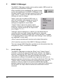
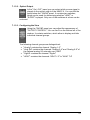
7.
MARC X Manager
The MARC X Manager enables you to perform audio, MIDI as well as
clock and synchronization settings.
After successful driver installation the symbol shown
on the right appears for the MARC X Manager in the
Windows taskbar. With a simple mouse-click you can
open a menu, in which you can select what kind of
settings you want to change.
"Mixer" opens the 32-channel DSP mixer, in
which all available audio signals are mixed to
three sums. In chapter "7.1.2 Mixer" these
settings are explained in more detail.
“Output Control“ opens the output control
window, in which you can determine the signal
routing for outputs as well as the output level
(see chapter "7.1.3 “).
"Settings" opens a dialog box, in which you can determine the
operating mode, and also change the settings for clock and
synchronization, DirectSound and GSIF, as well as MIDI. In chapter
"7.2 Operating Mode, Clock, MIDI and other Settings“ these settings
are explained in more detail.
„About“ opens a window with version and contact information.
„Exit“ ends the execution of the MARC X Manager software.
The user manual “DGX Extender” contains more information about the
integration of “DGX” in the Marc X Manager.
7.1.
Audio Settings
The MARC X Manager provides the "Mixer" and “Output Control“
windows, in which you can perform all audio settings. The "Mixer"
window visualizes the DSP based 32-channel mixer of the MARC X.
This mixer is integrated into the card's hardware and allows
instantaneous mixing of all available input signals as well as of all
playback signals to three stereo sums without additional CPU load. The
“Output Control“ window visualizes all available physical outputs. It
allows to route any output to one of the available input signals,
playback signals as well as one of the mixer's sums and to determine
the volume of an output. Both windows are subdivided in stereo
channels.
14
7.1.1.
Operating the Control Elements
The channels contain control and display elements.
In the following you will find some operating instructions:
• All rotary-buttons, faders and switches can be operated by using the
left mouse button.
• Active switches are illuminated.
• Rotary-buttons and faders can be reset to the standard value, e.g.
0 dB, by double-clicking the left mouse button.
• Each rotary-button and fader has a numeric value display, which can
be edited by double-clicking the left mouse-button followed by your
input using the keyboard. The input is finalized by the pressing the
<Enter> key or by selecting another control element.
• Each channel contains a stereo level indicator with peak LED’s (top)
and a "PRE" switch (bottom). If the switch is active, the level of the
source signal is indicated.
The peak LED’s are switched permanently to "PRE" and signal a
clipping of the source signal.
If level or peak indicators are switched to “PRE”, the level of the
signal prior the GAIN control is measured. The only exception are
the analog input channels. Since the GAIN is controlled in the AD
converter directly, “PRE” switched level or peak indicators
measure the level of the signal after the GAIN control but prior the
fader.
15
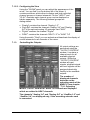
7.1.2.
Mixer
The "MIXER" allows mixing of available input signals and playback
signals to three stereo sums – to AUX1, AUX2 and the master sum.
The Mixer is divided in an input, a playback and a master section.
Within the input section an "INPUT" channel is assigned to each of the
Marc X inputs.
Within the playback section a "PLAY" channel is assigned to each of
the identical names playback devices, which can be found in the audio
device lists of your audio application.
Within each channel you can set the percentage of the channels signal
at the sum signals "AUX 1", "AUX 2" and the main sum. The master
section of the mixer contains a sum channel "MASTER". Here you can
set up the volume of the three sum signals.
The number of displayed channels depends on the operating
mode of the MARC X (see chapter "7.2.1 Operating Modes"). In the
operating mode "NON-ADAT Mode" ADAT inputs and outputs are
not available and will not be displayed in the mixer.
The input channels "Analog 3-4" and "Analog 5-6" or
“AesEbu 1-2” and “AesEbu 3-4” are displayed only, if the
according extender card is connected.
16
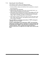
7.1.2.1. Input and Playback Channels
The input section of the mixer contains a separate "INPUT" channel for
each available input signal. The playback section of the mixer contains
a separate "PLAY" channel for each available playback device. In the
upper part of each channel, the channel is labeled with its name. Thus,
the corresponding input or playback channel can be uniquely identified.
If an input has several connection options (e.g. digital input: optical and
electrical, digital CD), then these options are offered at the top in the
channel in a dropdown list. Each channel provides the following
options:
• Using the "GAIN" control you can set the signal's
amplification prior the fader and the AUX controls.
The "GAIN" controls of the analog input
channels are in a darker red color in contrast to
all other channels. These "GAIN" controls set the
pre-amplification directly in the analog-digital
converter. This changes the level for all
applications globally, which take recordings
from this input. The “GAIN" controls of the
ADAT, the digital and the analog play channels
influences the signal level only within the mixer.
• Using the yellow rotary-buttons "AUX 1" and "AUX
2" the percentage of the signal in the according sum
can be determined. A "PRE" switch is assigned to
each of the AUX controls. If this switch is active, the
fader has no influence on the percentage of the
signal in the according sum.
• Using the blue rotary-button "BAL" (balance) you
can regulate the volume ratio between the left and
the right channel of the stereo signal.
• Using the fader in the lower part of the channel you can set the
signal's percentage on the main sum signal.
• Using the "Mute" switch you can mute the signal of the channel for
all sum signals. This way the signal of the channel is no longer
contained in the AUX sums or the main sum.
• If the "SOLO" switch is active in one or more channels, the main sum
contains exclusively the signals of these channels. The "SOLO"
switch has no influence to the AUX sums.
Each channel contains a stereo level indicator with peak LED’s (top)
and a "PRE" switch (bottom). If the switch is active, then the level of
the source signal is indicated.
There are some situations where the signal level cannot be
displayed for digital input channels. The cause is an improper clock
situation. In this case, two red LED’s illuminate the bottom of the
level indicator. Please refer chapter “7.2.2 Clock Settings” to learn
more about it.
17
The GAIN controllers of the analog inputs influence the level of
the source signal.
The peak LED’s are switched permanently to "PRE" and signal a
clipping of the source signal.
If level or peak indicators are switched to “PRE”, the level of the
signal prior the GAIN control is measured. The only exception are
the analog input channels. Since the GAIN is controlled in the AD
converter directly, “PRE” switched level or peak indicators
measure the level of the signal after the GAIN control but prior the
fader.
7.1.2.2. Master Section
The MASTER section is on the right side of the mixer. It
contains the sum channel "MASTER". In this channel the
volumes of the sum signals can be regulated:
• Using the two yellow rotary-buttons you can regulate the
volume of the sum signals "AUX 1" and "AUX 2".
• For setting the volume of the main sum you can use the
two faders in the bottom part of the channel. They are
assigned each to the left and right channel of the stereo
sum.
• Using the "Link" switch the two faders are connected with
each other and one fader controls the other. In this case
relative differences in volume are maintained.
• If at least one channel has activated the “Solo” switch,
the “Solo” LED in the master section illuminates.
• The channel contains a stereo level indicator with peak
LED’s (top) and "PRE" switch (bottom). If this switch is
active, then the level of the main sum signal prior the
fader is indicated.
The peak indicator is switched permanently to "PRE"
and signals a clipping of the main sum signal prior the fader.
18
7.1.2.3. Configuring the View
Using the "SHOW" panel you can adjust the appearance of the
mixer. You can find it on the bottom left of the mixer. It
contains switches, which allow to display and hide individual
channel groups or channel elements. For the "INPUT" and
"PLAY" channels each channel group can be displayed or
hidden separately. The following channel groups are
distinguished:
• "Analog" contains the channel "Analog 1-2"
• "Anlg Ext" contains the channels "Analog 3-4" and "Analog
5-6" of the optional analog I/O extender card "ANX"
• "Digital" contains the channel "Digital"
• "ADAT" contains the channels "ADAT 1-2" to "ADAT 7-8"
Using the switch "Parts" you can activate and deactivate the display of
control elements for all channels of the mixer.
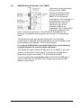
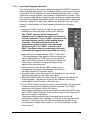
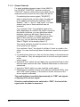
7.1.3.
Controlling the Outputs
All output settings are
performed using the
"OUTPUT CONTROL"
window. It contains a
channel each for all
available physical
outputs. Within the
"OUTPUT CONTROL"
window all input
signals, playback signal
and sum signals can be
assigned absolutely
flexibly to the available
outputs.
The number of
displayed channels
depends on the
operating mode of the
MARC X (see chapter
"7.2.1 Operating
Modes"). In the "NON-ADAT Mode" no channels are displayed
which are related to ADAT channels.
The channels "Analog 3-4" and "Analog 5-6" or “AesEbu 1-2” and
“AesEbu 3-4” are displayed only, if the according extender card
is connected.
19
7.1.3.1. Output Channels
For each available physical output of the MARC X,
the "OUTPUT CONTROL" window contains an
"OUTPUT" channel, where the source signal can be
selected and the volume for this output can be set:
For selecting the source signal ("SOURCE"),
which is played back via this output, the channel
in the upper part contains the switches "Play",
"Master", "Aux 1", "Aux 2"“ and "Input". For each
channel only one of these switches can be
activated.
If you activate “Play”, the playback signal of an
audio application is routed to the output. Using the
drop down list below, you can determine whose
playback signal can be heard. Each list entry
corresponds to a Marc X playback device name,
which is also used by your audio application.
Thus, e.g. you can hear the playback signal of
“Marc X Digital” at the analog output 1-2.
The central switches provide the selection of one
of the mixer's sum signals.
If you activate “Input”, the signal of an Marc X input is routed to the
output. You can use the drop down list below to specify the required
input.
• For setting the volume you can use the two faders in the bottom part
of the channel. They are assigned each to the left and right channel
of the
output signal.
• Using the "Link" switch the two faders are connected with each other
and one fader controls the other. Relative differences in volume are
maintained.
• Using the "Mute" switch you can mute the output signal.
• Each channel contains a stereo level indicator with peak LED’s (top)
and "PRE" switch (bottom). If the switch is active, the level of the
source signal is indicated.
The peak indicator is switched permanently to "PRE" and signals
a clipping of the source signal.
If level or peak indicators are switched to “PRE”, the level of the
signal prior the fader is measured.
20
7.1.3.2. Optical Output
In the "Opt. OUT“ panel you can select which source signal is
played on the optical output of the MARC X. You can find the
panel below the "SHOW" panel. It contains two switches,
which can be used for determining whether "ADAT" or
"S/PDIF" is played. Only one of the switches at a time can be
activated.
7.1.3.3. Configuring the View
Using the "SHOW" panel you can adjust the appearance of
"OUTPUT CONTROL". You can find it on the bottom left of the
window. It contains switches, which allow to display and hide
individual channel groups.
The following channel groups are distinguished:
•
•
•
•
"Analog" contains the channel "Analog 1-2"
"Anlg Ext" contains the channels "Analog 3-4" and "Analog 5-6" of
the optional analog I/O extender card "ANX"
"Digital" contains the channel "Digital"
"ADAT" contains the channels "ADAT 1-2" to "ADAT 7-8"
21
7.2.
Operating Mode, Clock, MIDI and other Settings
You can find the dialog box for these settings by selecting the menu of
the MARC X Manager – "Settings". Here you can determine the
operating mode of the MARC X as well as the settings for clock and
synchronization, DirectSound and GSIF, and MIDI.
Please note that some settings and labeling are different in Windows™
95/98/ME and Windows™ 2000/XP.
The user manual “DGX Extender” contains more information about the
integration of “DGX” in the Marc X Settings.
7.2.1.
Operating Modes
The setting "Operating Mode” has global influence on the behavior of
the MARC X. The MARC X can be operated in two different modes:
• in "ADAT Mode", for using all inputs and outputs including the ADAT
channels. In this mode the sample frequency for all available
channels is limited to a maximum of 48 kHz + 15% pitch.
• in "NON-ADAT Mode“. This mode excludes the usage of ADAT
inputs and outputs. In this mode a sample frequency of up to 96 kHz
+ 15% pitch is allowed for all remaining channels.
The "ADAT Mode" limits the maximum available sample frequency
to 48 kHz + 15% Pitch. The "NON-ADAT Mode" excludes the
usage of ADAT channels.
22
7.2.2.
Clock Settings
For digital audio processing a clock is always required. You could
easily compare this with the engine of a car. If the engine does not run,
you cannot drive the car.
The clock is the engine that powers the digital audio processing. The
sample rate is derived from the speed of the clock.
In the "Clock Setup" you determine, which of the clock sources is used
for recording, playback, mixer and monitoring of the MARC X. The
selected clock source generates the sample rate, which is used to
perform these functions.
If you have selected "Internal Clock", then
the MARC X generates the clock itself and
is independent from other external devices.
This setting is also called Clock Master.
External devices can receive the clock,
which is generated by the MARC X, if they
are connected by the Wordclock output,
S/PDIF output or ADAT output. These
devices can be configured as Clock Slave
and then work synchronously with the
MARC X.
For "S/PDIF Input" and "ADAT Input" the clock results from the digital
audio input signal.
If you select "Wordclock Input", the clock on the Wordclock of the
"MWX" input is interpreted and used as Wordclock.
If you select "Superclock Input", the clock on the Wordclock input of the
"MWX" is interpreted and used as Superclock.
If you select "SyncBus Clock“, the clock of another MARIAN card,
which is configured as clock master, is used.
Please note, that only if you select "Internal Clock”, the application
program is able to determine the sample rate. For all other clock
sources the sample rate is determined by external connected devices.
In such cases MARC X works as clock slave and consequently
synchronously with the external clock.
If you select another clock source as "Internal Clock", please
ensure, that a suitable is connected to the according port,
switched on and outputs a valid signal or valid clock.
For processing digital audio input signals, e.g. for recording,
monitoring, mixing or gathering the input level, it is necessary, that the
MARC X locks onto the digital input signal. In order to achieve this, you
will have to switch the clock source of the MARC X to the appropriate
input, e.g. for using the S/PDIF input, you have to switch to "S/PDIF
Input" and for using the ADAT input, choose "ADAT Input".
23
Or you activate the option "Choose Clock Source automatically". If this
option is active, the driver of the MARC X first of all chooses "Internal
Clock". If you start using one of the digital audio input signals, then the
driver of the MARC X will switch to a suitable clock source. The driver
switches to "Internal Clock" again, when the digital audio input is no
longer used.
If the digital signal of the input is based on the used clock source, then
the required switch-over to the clock source of the digital audio input is
not necessary. Examples:
1.
You work with an external ADAT device, e.g. the ADAT converter
MARIAN ADCON or the ALESIS ADAT XT. If the "Internal Clock"
is selected as clock source for the MARC X, it works as clock
master. If you configure the MARIAN ADCON as clock slave
(AD/DA Mode) or set the clock select of the ADAT XT for instance
to "EXT 44.1 kHz“, these devices return the receiving clock from
the MARC X using its digital audio signal back to the MARC X - the
input signal of the MARC X is also based on its own internal clock.
2. You work with ADAT and S/PDIF devices, which have a Wordclock
input. Select "Internal Clock" as clock of the MARC X (clock
master) and connect the Wordclock output of the MARC X (port on
"MWX") with the Wordclock inputs of your devices. Configure
them, so that they operate as clock slave of the Wordclock input.
The clock of the digital audio signals of these devices is now
based on the internal clock of the MARC X. Now the MARC X is
able to process these signals at its digital inputs. Also a
simultaneous processing of both signals is possible, because the
clock of these signals is synchronized.
3. You work with external ADAT and S/PDIF equipment, which is
embedded in a Wordclock environment with an existing Wordclock
master. Select "Wordclock Input" for the MARC X, which now
operates as clock slave. The digital audio input signals of the
MARC X (S/PDIF and ADAT) are now based on the same clock,
which you have set to be used ("Wordclock Input"). This way you
can use S/PDIF and ADAT input signals without having to switch
to the according clock source.
You setup this condition in the MARC X driver by using the option
"Clock of digital audio inputs is synchronized with this clock". Activate
this option, if one of the above-mentioned clock configurations can be
compared with your conditions. In this case the driver allows to use a
digital audio input, even if the suitable clock source is not set.
Activate the option "Card is SyncBus Master”, if the MARC X should
operate as clock master for the SyncBus. The clock of the configured
clock source will be put on the SyncBus and can be used by other
connected MARIAN cards as clock source. These cards then operate
as clock slave of the MARC X and consequently synchronously.
24
If several cards are to be synchronized using the SyncBus,
exactly one card has to be configured as master. All other cards
have to be configured as slave.
If you work with an ASIO application program, all clock settings will be
performed within this program. In this case clock settings performed in
the MARC X Manager are ignored. Please refer to the user's guide of
your ASIO application program in order to learn how clock sources are
selected. In all cases the ASIO driver of the MARC X assumes, that the
clocks of the digital input signals are based on the clock source, which
you have selected. Internally it activates the option "Clock of digital
audio inputs is synchronized with this clock”.
7.2.3.
Internal Clock
"Default Rate"
This input field contains the sample rate, which
the internal clock is operated with, as long as
the MARC X is not used by recording or
playback. If the internal clock is the active clock source, then the mixer
as well as the signal routing operates with this sample rate.
Some application programs finish to work with MARC X on a short-term
basis, if you stop the recording or playback, or if you re-position the
playback cursor (Song Position Pointer) during playback. If you use
another sample rate than the configured one, when working with such a
program, then setting the "Default Rate" could have cracks as a
consequence. We recommend to enter the same sample rate in to this
input field, which you use for your application program.
7.2.4.
Wordclock Output
The Wordclock output of the MARC X always
outputs the clock of the currently selected clock
source. At this point you determine, whether
the clock output of the "MWX" should output
this clock as Wordclock or as Superclock.
25
7.2.5.
Start/Stop Synchronization
If you use a MME, WDM-Audio or DirectSound
application program with more than one
recording or playback device of the MARC X,
you will have to determine, whether you want
to operate these devices synchronously or
independently from each other.
"Independent Start/Stop" allows an independent start/stop of the
devices, i.e. assuming to have separate sound cards. Most radio
automation programs and also DJ programs require this setting.
"Synchronous Start/Stop" guarantees that all used devices are started
and stopped sample-synchronously. This is required for multi-channel
projects of most hard-disk recording programs.
"SyncBus synchronous Start/Stop" guarantees that all used devices
are started and stopped sample-synchronously, even if they are
positioned on different MARIAN sound systems, which are connected
by the SyncBus. This is required for multi-channel projects of most
hard-disk recording programs, if you use devices of several MARIAN
cards.
If you work with an ASIO application program, then these settings are
automatically performed by the ASIO drivers of the MARC X.
26
7.2.6.
Clock and Sample Rate Conflicts
Based on the samples described in chapter "7.2.2 Clock Settings" it is
likely that it may lead to situations, in which certain request to the
MARC X cannot be served. Examples:
• You already use the internal clock for recording or playback and also
try to use the S/PDIF or ADAT input. It's possible that a clock switchover is necessary, which however would "interfere“ a running
recording or playback. In this case the MARC X drivers will refuse
the usage of S/PDIF or ADAT inputs.
• You use a MARC X device with a certain sample rate and you want
to you use one more device with a differing sample rate. In this case
the drivers will also refuse the last mentioned, because only one
sample rate at a time can be active.
• The MARC X is configured as clock slave and consequently
operates synchronously with an external clock source. If you try to
use a device with a sample rate which differs from the external
sample rate, the driver will refuse the usage of this device.
If one of the above-mentioned or a comparable situation occurs, then
the driver will inform you with a suitable warning or error message.
Often this is obstructive, because some application programs and the
Microsoft DirectX test all available recording and playback devices at
start-up, which subsequently leads to an accumulation of such
conflicts. For quite some time you would be busy to confirm these
messages of the driver by clicking "OK". This is the reason why these
error message are disabled after installation.
If you have problems when using recording or playback devices and
you want to see their causes, the error message by switching off the
option "Deactivate error message caused by clock and sample rate
conflicts"). Warning and error message can be quite useful when
searching for problem causes.
27
7.2.7.
Setting up the driver interfaces in Windows™ 95/98/ME
Here you can determine the settings for application programs which
use DirectSound or the TASCAM GigaSampler Interface (GSIF) in
Windows™ 95/98/ME.
7.2.7.1. Section "Direct Sound"
In this section you determine the settings for applications, which use
DirectSound as driver interface.
Here are some information in advance: the ideal settings for the
DirectSound usage depend on some factors in your PC. Because of
this we cannot recommend any ideal settings, but can provide you
some information on what's behind the possibilities for the settings. You
will have to test yourself, what settings will suit best. Anyway, using the
standard settings will ensure a trouble-free operation.
”Adjust Latency Manually”
Moving the time control changes the size of the audio buffer on the
card. If the settings for the latency period is too low, it may result in
interruptions. In this case you will have to increase the latency period.
28
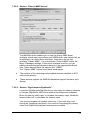
"Restrict playback format to:"
When using certain audio programs with DirectSound it may happen,
that the DirectX system attempts to open the driver using a different
sample format, than the audio programs intends to use. This results in
a real time conversion of the signal format by the DirectX system. This
conversion may have negative influence on the sound and system
performance.
If a playback using DirectSound does not sound correct, you will have
to set the signal format, which you use in the audio software. This way
the DirectX system is forced to exclusively open the driver using the set
format in the MARC Manager and the real time conversion is
inapplicable.
”Available Playback Devices limited to:”
Here you can adjust the (stereo) output for DirectSound applications,
which have no selection of the output. The output of the audio signals
is then restricted to this (stereo) output.
7.2.7.2. Section “GigaSampler/GigaStudio”
We cannot inform you about the ideal settings for GSIF but will explain
to you, what the terms stand for. In order to find the most suitable
settings you will have to test.
“Granularity” and “Latency”
The granularity specifies the size of the audio data blocks, which are
transferred to the hardware by the GigaSampler. The smaller the
latency was set, the smaller the data blocks will have to be, in order to
avoid interruption during playback (granularity: “Fine”). Though the
system is more stressed because of the larger data overhead during
the transfer, the reaction time for the sampler playback is shorter.
Larger data blocks (granularity: “Coarse”) stress the system less, but
the reaction time is longer and leads more easily to interruptions during
playback.
For ideal results try to set the values of the two faders as low as
possible.
29
7.2.8.
Setting up the driver interfaces in Windows™ 2000/XP
7.2.8.1. MME and DirectSound
Audio applications, who do not use ASIO, GSIF or direct WDM-Audio
(like Cakewalk Sonar), communicate with Microsoft MME or Microsoft
DirectSound drivers instead of communicating with the MARIAN drivers
directly. The Microsoft drivers in turn communicate with the MARIAN
WDM-Audio drivers.
For audio applications, who use these Microsoft drivers, apply:
•
They can playback simultaneously using the same playback device.
The Microsoft Kernel Mixer mixes the playback signals of the
applications into one stereo stream and routes it to one physical output
device. If playback takes place with different sample rates, the
Microsoft Kernel Mixer converts the sample rate of the playback
streams to the highest sample rate required.
Hint: You can improve the quality of this conversion! (See Control
Panel | Sounds and Audio Devices | Audio | Sound Playback |
Advanced | System Performance)
•
The described simultaneous playback of different applications fails, if
the output device is already in use by ASIO, GSIF, "Classic MME" or
direct WDM-Audio.
•
The number of the available recording and playback devices is limited:
- under Windows 2000 to 10 devices each (20 channels)
- under Windows XP to 32 devices each (64 channels)
This limitation applies to the number of all audio devices installed in the
system.
You can use "Classic MME" or ASIO to walk around this limitation.
•
The minimum possible latency is limited to app. 30ms through the
Microsoft Kernel Mixer architecture.
Use ASIO or GSIF to walk around this limitation.
•
Some audio applications show additional audio devices with their
names appended by "(3+4)" or "(5+6)". This is caused by an anomaly
of the Microsoft MME/DirectSound system. Please ignore these
devices and do not use them.
•
Some audio applications require the MARIAN driver because of its
additional hardware support functions:
- Hardware Punch In Monitoring
- Hardware Pitch Support
- Hardware Audio Signal Routing
- Hardware Audio Signal Level Measurement
These functions are not supported by the Microsoft drivers. Please
supply this audio applications with the "Classic MME" devices.
30
7.2.8.2. Section “Classic MME Drivers”
The MARIAN driver enables you to use the former MME driver
interface, which was conventional until WDM-Audio was introduced, as
an addition to all other driver interfaces. From now, we call this
interface "Classic MME". You can activate "Classic MME" within the
Marc X Manager settings. If this driver interface is active, you get
additional recording and playback devices in the appropriate device
lists. These devices have the name suffix "(MME)".
The "Classic MME" device have these advantages:
•
The number of the recording and playback devices available is NOT
limited (see above)
•
These devices support the MARIAN hardware support functions (see
above)
7.2.8.3. Section “GigaSampler/GigaStudio”
In section GigaSampler/GigaStudio you can setup the latency between
a Tascam GigaStudio MIDI event and the resulting sound playback.
Move the latency slider right, to increase the latency value. Mode the
latency slider left, to decrease the latency value.
You should increase the latency value only, if you hear drop outs
during the GigaStudio playback. As a result of increasing the latency
value, the GigaStudio playback becomes more stable.
31
The latency also depends on the playback sample rate. You can
choose another sample rate to show the resulting latency value – you
will not change the sample rate. The actual GigaStudio sample rate is
shown in blue color.
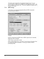
7.2.9.
MIDI Settings
In this tab you can edit and especially filter all MIDI commands
processed by the MARC X.
"Device"
Here you can select the MIDI input or MIDI output for the command,
which you wish to change.
"MIDI stream optimization active"
When enabling this option, you filter all unnecessary information from
the transmitted MIDI commands. This way you achieve shorter
processing times.
32
7.2.9.1. Section "Command Filters"
In the Command Filter section channel related commands are
processed. There are three view modes available: "View by
command", "View by channel" and "View by matrix".
The related level for the "View by command" are the individual MIDI
commands. This gives you the possibility to filter or transmit a
command on the individual MIDI channels. Using the On” and Off”
buttons you can filter or transmit the command.
Please note, that enabling a checkbox means setting the
appropriate filter, i.e. the non-transmission of the MIDI command.
The related level of the "View by channel" are the individual MIDI
channels and provides the filtering or transmission of the individual
commands for the selected channel.
The "View by matrix" shows all settings in an overview. The columns
show the 16 MIDI channels and the rows show the MIDI commands.
33
7.2.9.2. Section "System Data Filters"
In this section you can filter the channel independent MIDI commands
like system commands. All performed settings also apply for the
selected MIDI device.
34
8.
ASIO Settings
The picture on the
right shows the
ASIO controls
panel of the
MARC X driver.
You can open this
panel within your
ASIO application
program. Please
refer the manual
of this program to
learn where the
ASIO control
panel can be
opened.
By enabling the
checkboxes in
front of the entries
of the inputs and
outputs you
determine, which
devices the ASIO
application can
'see' and use.
You can change the listed "Name (Alias)" in the first column by doubleclicking the entry. This way you can rename it as you like.
Hint: Only activate the playback and recording devices which you
really want to use within you project! Each activated device
reserves system resources and CPU load – even if you do not
use the device in you audio project.
Please note that additional settings are necessary to use all
selected devices within your ASIO application. For details please
refer to the manual of your application program.
If you activate an ADAT or S/PDIF recording device, please ensure that
the according input signal is based on the clock source which you
choose within your ASIO application. Only in this case a proper
recording is possible. Please see chapter “7.2.2 Clock Settings” for
more details.
The slider "Execution priority" determines in "high" position, that the
transmission of ASIO data is given a high processor priority. In the
position "low" it is given to real time calculation of Plug-Ins.
Every audio application uses buffers to transfer the audio data to and
from the hardware. These buffers work like containers. During playback
35
the application fills the container with the playback data and the driver
empties this container. The size of the container determines the latency
between a live event (like a midi event or live recording) and the
resulting playback. The latency grows with the size of the buffer.
You can setup the buffer size with the field “Buffersize in Samples”.
Here you can tell the driver how many samples should fit in the
container. The resulting latency value, expressed as a time value like
milliseconds, depends on the sample rate. The most ASIO audio
applications show this value when you close the ASIO setup dialog of
the driver.
36
9.
Software Samplers and Synthesizers
Software samplers and synthesizers normally supply MIDI output
devices for other audio applications which want to use the software
sampler as an instrument. If such an application starts, then normally
this application opens the MIDI output devices and this in turn causes
the software sampler to initialize its audio engine with the configured
audio outputs.
This occurs even if you have NOT started the software sampler
application.
In this situation the software sampler and the other audio application
may conflict, if they use the same audio output. If you use other driver
interfaces than Microsoft MME or DirectSound, you can use the Marc X
with different audio applications at the same time but never the same
output device simultaneously.
Therefore this hint:
•
First start the software sampler/synthesizer and setup an audio output
device which will NOT be used by the other audio application. Start the
audio application (sequencer) afterwards.
•
If you start an ASIO or GSIF application the first time, then it will use
the device "Marc X Analog 1-2" for recording and playback.
The Windows Multimedia System also supplies a software synthesizer
called "Microsoft GS Wavetable SW Synth". This synthesizer has also
a MIDI output port with the same name. Since there is no explicit setup
for the output device, the "Microsoft GS Wavetable SW Synth" always
uses the standard playback device configured in "Control Panel |
Sounds and Multimedia | Audio".
37
10.
Technical Data
•
•
•
•
•
Stereo Analog I/O (1/4’’ TRS jack)
Stereo Digital I/O S/PDIF (RCA and TOSLINK)
8-channel Digital I/O ADAT (switch able to TOSLINK)
Audio Connector for internal Digital Audio CD/DVD drive
Audio Connector for internal Analog Audio CD/DVD drive
•
•
•
•
•
•
•
•
•
•
Sample formats: 8, 16, 20, 24, 32 Bit Mono/Stereo
Sample rates Analog: 8 - 96 kHz +/- 15% Pitch
Sample rates Digital: 32 - 96 kHz +/- 15% Pitch
Sample rates ADAT: 32 – 48 kHz +/- 15% Pitch
Frequency response @ 44,1 kHz: 20 Hz to 20 kHz
Frequency response @ 96 kHz: 20 Hz to 40 kHz
Maximum input and output level: +8 dBu
Signal-to-noise ratio S (N+D) AD: 104 dB(A)
Signal-to-noise ratio S (N+D) DA: 114 dB(A)
THD: 0,005%
Included Wordclock/MIDI extender board „MWX“
• 2 MIDI I/O via adapter cable
• Wordclock I/O, Superclock I/O (BNC)
Optional Analog I/O extender board „ANX“
• 2 Stereo Analog I/O (1/4’’ TRS jack)
Optional AES/EBU extender board „DGX“
•
•
•
•
•
•
•
38
2 AES/EBU I/O (XLR via breakout cable)
Output voltage 3Vss on 110 Ohm
Output sample rate: 8 – 108 kHz
Input sensibility approx. 200mVss
Input impedance: 110 Ohm
Input sample rate: 32 - 96 kHz
Input sample rate converters:
Input SNR:
128dB
Input THD+N : 0,00032%
Max. sample rate ratio In/Out: 1:3 resp. 3:1
11.
Service and Support
If you have any questions or problems during the installation or
operation of your MARC X please perform the following steps:
1.
Ensure that you always have the latest driver installed. You find
the current driver files on the following internet page:
www.marian.de/en/downloads
2.
Have a look in our Audio Guide, which has been published on the
internet, whether you can find a solution to your problem or an
answer to your question. Here you also find the Audio Guide:
www.marian.de
3.
If any questions still remain, you can contact us via the internet
using our support form at:
www.marian.de/en/support
or give us a phone call:
+49 341 5893222.
Interesting news, information and driver updates you can find here:
www.marian.de.
You can contact our Sales Department on the internet at
www.marian.de or [email protected].
39


![[English] 1 MB](http://vs1.manualzilla.com/store/data/005724727_1-d0907da86b06d0402fef0dce028404c5-150x150.png)