1
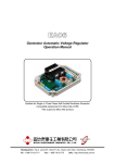
ADVR-2200M Universal Hybrid Analog-Digital Voltage Regulator Operation Manual Hybrid Universal Analog / Digital 1 or 3 Phase 3.5 Amp Self Excited, Shunt, Auxiliary Winding, Harmonic Power or PMG Automatic Voltage Regulator Easy to Set-Up and Program Install Manual Headquarters : No.3, Lane 201, Chien Fu St., Chyan Jenn Dist., Kaohsiung, TAIWAN Tel : + 886-7-8121771 Fax : + 886-7-8121775 URL : http://www.kutai.com.tw SECTION 1 : SPECIFICATION Sensing Input (E1, E2, E3) RMS Reading Voltage 220 600 Vac, 1 phase / 3 phase DIP switch setting 180 280 Vac @ 220 Vac 330 515 Vac @ 380 / 440 Vac 420 660 Vac @ 480 / 600 Vac Frequency 50/60 Hz, DIP switch setting Power Input (P1, P2) Voltage 60 300 Vac, 1 phase 2 wire Frequency 50 500 Hz Auxiliary Input (P3, P4) Voltage 40 300 Vac, 1 phase 2 wire Frequency 40 500 Hz Excitation Output (F+, F-) 110V 1 phase Continuous 63 Vdc 3.5A Max. 90 Vdc 7A for 10 secs. 220V 1 phase Continuous 125 Vdc 3.5A Max. 180 Vdc 7A for 10 secs. 220V 3 phase Continuous 150 Vdc 3.5A Max. 215 Vdc 7A for 10 secs. Resistance ≧ 13 ohms @ power input 110 Vac ≧ 25 ohms @ power input 220 Vac Max. 100 ohms Fuse Spec. Slow blow 5 x 20 mm S505-5A External Voltage Adjustment (VR1, VR2) Max. +/- 5% @ 500 ohms 1 watt potentiometer Max. +/- 10% @ 1K ohm 1 watt potentiometer Voltage Regulation Less than +/- 0.5% ( with 4% engine governing ) Build Up Voltage 5 Vac 25 Hz residual volts at power input terminal Soft Start Ramp Time 4 sec. +/- 10% Response Time Less than 20 milliseconds Static Power Dissipation Max.12 watts Burden in SHUNT & PMG Wiring 550 VA @ power input 110 Vac 1100 VA @ power input 220 Vac Quadrature Droop Input (C1, C2) CT 1A or 5A greater than 5VA (DIP switch setting) Sensitivity +/- 7% @ PF +/- 0.5 (Droop adjustable) Analogue Input (A1, A2) Input resistance greater than 2K ohms Max. Input +/- 5 Vdc or +10 Vdc Sensitivity 1 Vdc for 2.5% Generator Volts (adjustable) Under Frequency Protection (Factory Presets) 50 Hz system presets knee point at 45 Hz 60 Hz system presets knee point at 55 Hz Over Excitation Protection Set point 125 Vdc +/- 4 % @ power input 220 Vac Inverse-time curve. This function can be turned off. Voltage Thermal Drift Less than 3% at temperature range -40 to +70 ˚C Under-Frequency Knee Point Thermal Drift Less than +/- 0.1 Hz at -40 to +70 ˚C Environment Operation Temperature Storage Temperature Relative Humidity Vibration -40 to +70 ˚C -40 to +85 ˚C Max. 95% 5.5 Gs @ 60 Hz Dimensions 150.0 (L) x 135.0 (W) x 55.5 (H) mm 5.91 (L) x 5.31 (W) x 2.19 (H) inch Weight 470 g +/- 2% 1.04 lb +/- 2% EMI Suppression Internal electromagnetic interference filtering ___________________________________________________________________________________________ 2 ADVR-2200M SECTION 2 : OUTLINE / SIZE / INSTALLATION REFERENCE Unit : mm Figure 1 Outline Drawing ATTENTION 1. AVR can be mounted directly on the engine, genset, switchgear, control panel, or any position that will not affect operation. For dimension reference, please see Figure 1. 2. All voltage readings are to be taken with an average-reading voltmeter. 3. Terminal:“Fast-On” terminals 6.35 mm (1/4 inch). SECTION 3 : DIP SWITCH PROGRAMMING ON SW1 ON SW1 SW2 1 2 SW1-1 & SW1-2 Sets the Generators Sensing Voltage 1 2 3 4 5 6 SW2 SW2-1 Set Sensing Voltage for 1 or 3 Phase SW2-2 Set Generator Frequency SW2-3 Set Over Excitation Protection ON or OFF SW2-4 & 5 Sets Generator Capacity SW2-6 Sets Capacity of Droop CT ___________________________________________________________________________________________ ADVR-2200M 3 SECTION 4 : ADJUSTMENTS U/F Under Frequency Protection Adjustment When generator s p e e d falls below the knee point, the under frequency protection circuit will activate and the voltage and frequency begin to decrease in linear descend. Select frequency 50 or 60 Hz according to the generator in use. LED Indicator lit up when the generator is in U/F (Under Frequency Protection) and O/E (Over Excitation Protection). DROOP Droop Adjustment When paralleling, the AVR increase or decrease its voltage output, when phase current leads or lag the voltage. The increase and decrease range can be preset by the DROOP adjustment. DIP U/F Dip Adjustment When U/F protection is activated, the voltage droop ratio can be adjusted via this DIP (POT). The adjustable range is 310 V/Hz. STAB Stability Adjustment Correct stability adjustment must be conducted while the generator is operating without load. First adjust the STAB potentiometer (POT) anticlockwise until the voltage becomes unstable, and then slightly adjust it clockwise (About1/5 turn). When the voltage just reaches the critical point (Knee point) of stabilization, where the voltage is stable yet very close to becoming unstable. VOLT Voltage Adjustment Generator rated output voltage adjustment. Must be in accordance with the DIP Switch SW1-1 & 2 voltage range setting. TRIM Trim Adjustment When terminal A1 and A2 are biased with a DC voltage (010V), the TRIM is then used to adjust the influence on the output voltage of the AVR. If the TRIM (POT) is adjusted fully counterclockwise, any bias voltage will not cause any influence. On the contrary if the TRIM is adjusted fully clockwise, then any signal will produce a maximum 10% effect. Figure 2 SECTION 5 : WIRING CONNECTIONS ON P3 P4 Aux. Power Input P4 and P1 are concurrent (internal short circuit) ON ON C2 Set the DIP SW Correctly C2 P4 P4 CT is only used when paralleling ADVR-2200M VR1 0 to 10 Vdc Analog lnput Only use when Paralleling to Correct (PF) E1 E2 VR2 A1 A1 A2 A2 P2 P1 F+ F- E1 CT. N E3 P2 P1 F+ F- R N Stator Wires Generator PMG Figure 3 PMG Connection Exciter R E2 CT. T S Exciter T S ADVR-2200M VR1 VR2 E3 Set the DIP SW Correctly P3 P3 VR1 & VR2 are Normally Bridged and Voltage is Adjusted on the PCB 1K Ohm 1W ON C1 C1 Stator Wires Generator Figure 4 Shunt Connection (220V) ___________________________________________________________________________________________ 4 ADVR-2200M ON ON C1 C2 Set the DIP SW Correctly P3 P4 ADVR-2200M VR1 VR2 A1 A2 E1 E2 E3 P2 P1 F+ F- (Harmonic) AUX. wires CT. Exciter T S R N Stator Wires Generator Figure 5 Auxiliary Winding (AUX.) Connection Shunt with IVT wiring diagram ON ON C1 C2 Set the DIP SW Correctly P3 P4 ADVR-2200M VR1 VR2 A1 OUT1 OUT2 S1 S2 Droop % A2 Time ON Test IVT Fuse Output Ready Test Batt-Volt OVLD B E1 B+ E2 E3 P2 P1 F+ F- CT. + Exciter T S R N Stator Wires Generator Figure 6 IVT-1260 / IVT-2460 & ADVR-2200M Wiring Connection 1. 2. 3. 4. 5. 6. ATTENTION All AC voltage readings are average value only. Use a remote 500 ohms 1 watt external VR for +/- 5% adjustment range. (keep shorted if not used) Use a remote 1K ohm 1 watt external VR for +/- 10% adjustment range. Sensing Voltage can be set from 220 – 600 Vac Program SW1-1 & 2 correctly. For single phase sensing bridge E2 & E3 and move SW2-1 to OFF. If your PMG is not working you can also power the AVR in shunt using terminals P1 & P2 connected to the output of the generator as long as it’s less than 277 Vac. ※ Use only the replacement fuses specified in this user manual. ※ Appearance and specifications of products are subject to change for improvement without prior notice. ___________________________________________________________________________________________ ADVR-2200M 5