1
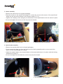
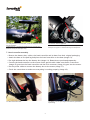
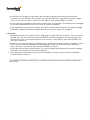
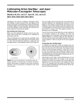
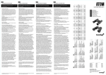
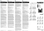
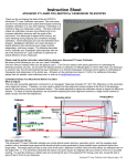
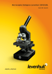
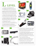
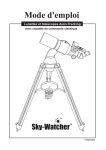
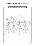
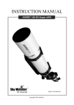
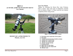
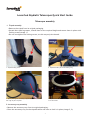
Levenhuk SkyMatic Telescopes Quick Start Guide
Telescope assembly
1. Tripod assembly
• Remove the tripod from its original packaging.
• Spread the tripod legs apart, extend them to the required height and secure them in place with
locking screws (image 1).
• Do not overtighten the locking screws, as this may strip the thread.
1. Tripod locking screw
2. Tripod bracket for the accessory tray
3. Upon placing the accessory tray on the bracket, rotate
the tray to fix it in place
4. Tripod head without the mount. The clamping screw
is in the center
2. Accessory tray assembly
• Remove the accessory tray from its original packaging.
• Place the accessory tray on the tripod bracket and twist to lock it in place (image 2, 3).
1
3. Mount assembly
• Remove the mount from its original packaging.
• Place the mount on the tripod head (image 4), so that the screw at the center of the tripod head
slides into the slot at the bottom of the mount (image 4, 5, 6).
• Tighten the clamping screw (image 4) at the bottom of the tripod head to lock the mount in place.
• Do not overtighten the screw, as this may strip the thread.
5. Attaching the mount to the tripod head
6. Clamping screw of the tripod head
4. Optical tube assembly
• Remove the optical tube from its original packaging.
• Do not remove the dust cap from the objective lens during assembly and try not to touch the
optics, as this may damage the coating.
• Attach the optical tube to the dovetail plate on the mount and secure it in place with the locking
thumbscrew (image 7).
• Do not overtighten the thumbscrew, as this may strip the thread.
7. Locking thumbscrew on the mount
8. Dovetail plate on the optical tube
2
5. Finderscope assembly
• Remove the finderscope and its mount from the original packaging.
• Slide the rubber ring to the center of the finderscope, insert the finderscope into its mount and
secure it in place with thumbscrews.
• Slide the finderscope mount into the dovetail plate on the optical tube (image 8) and lock it in
place with the thumbscrew (image 9).
• Do not overtighten thumbscrews, as this may strip the thread.
• Align the finderscope with adjustment screws, as necessary (image 10).
9. Tighten this thumbscrew to lock the finderscope mount
in place
10. Adjustment screws for alignment of the optical axis
6. Eyepiece and diagonal mirror assembly
• Remove the 25-mm eyepiece and diagonal mirror from their original packaging*.
• Loosen the thumbscrew on the focuser and remove the plastic cap. Insert the eyepiece into the
diagonal mirror* and then insert the diagonal mirror into the focuser (image 11). For models
without diagonal mirrors**, the eyepiece should be inserted directly into the focuser (image 12).
3
11. Fully assembled optical tube, with the diagonal mirror
and an eyepiece
12. Focuser with an eyepiece
**There is no need to use a diagonal mirror with reflectors;
therefore an eyepiece is inserted directly into the focuser.
*Diagonal mirror is included in standard kits of refractors and
Maksutov-Cassegrain telescopes only.
7. Hand controller assembly
• Remove the battery box, cables, the hand controller and its base from their original packaging.
• Attach the base to a tripod leg and place the hand controller on the base (image 13).
• Put eight AA batteries into the battery box (image 14). Batteries are purchased separately.
• Connect the hand controller to the mount with a special cable. Make sure the RJ-6 connector
(image 15) goes into the hand controller and the RJ-4 connector (image 16) goes into the mount.
• Use the power cable to connect the battery box to the mount (image 17).
• Check the connections to make sure everything is working properly (image 18).
13. Hand controller base
14. Battery box accepts eight AA batteries (purchased
separately)
4
15. RJ-6 connector of the hand controller cable
16. RJ-4 connector of the hand controller cable goes into
the mount
8. Finishing the assembly
• Make sure the telescope is completely leveled (check the spirit level on one of the tripod legs to
confirm (image 19).
• Upon finishing the assembly, remove the dust cap from the objective lens (image 20).
• You can now proceed with setting up the database and observing the night sky.
17. Power cable connected to the mount
18. If both cables are connected properly, the hand
controller starts operating. A beep will notify you of this
5
20. Dust cap of the objective lens
19. Spirit level (the bubble has to be within the center
ring)
First setup
Before you can use the database of your new telescope for celestial observations, you need to set it
up with the hand controller. Follow this simple procedure:
1. Make sure the mount is leveled and the tripod is stable.
2. Enter the current coordinates with the hand controller: input the longitude first, followed by
the latitude, e.g. 060 04' W 49 09' N. Use the scroll keys to select the required cardinal direction
(W for west, E for east, N for north and S for south). Input the current time zone in hours and
minutes (+ for Eastern Hemisphere, – for Western Hemisphere). Confirm each input by pressing
ENTER.
Note: use maps.google.com to find out your current coordinates and worldtimezone.com to find
out your current time zone.
3. Enter the current date in MM/DD/YYYY format. Confirm the input by pressing ENTER.
4. Enter the current time in 24-hour format. Confirm the input by pressing ENTER.
5. Upon entering the current time, you will be prompted to set up the daylight saving time. Use
scroll keys to select YES or NO and press ENTER to confirm.
6. Once you are finished with these settings, a Begin alignment? message will appear on the
screen.
Select the alignment method you want to use (Brightest Star Align or 2-Star align) and press
ENTER to confirm.
Brightest Star Align
• You will be prompted to select the region of observations from eight options, i.e. N, NE, E, SE, S,
SW, W, NW. Each direction covers a span of 90° along the azimuth. Select the required region
and confirm by pressing ENTER.
• The hand controller will then compile a list of bright stars in the observed region. The first line
denotes the name and magnitude of the star. The second line tells you the approximate location
of the star. Choose a star from the list and press ENTER to continue.
6
• You will have to navigate to the chosen star manually with the direction keys on the hand
controller. You can increase the rotation rate with the RATE key on the hand controller (ranges
from 0 to 9). Once the star is centered in the field of view, press ENTER to confirm.
• You will then be prompted to select the secondary star for alignment. The telescope will navigate
to this star automatically, but you will have to center it manually.
• If the alignment has been done properly, you will be notified with Alignment Successful message.
Otherwise, Alignment Failed will appear and the process will have to be repeated.
2-Star align
• The hand controller will compile a list of bright stars, visible from your location. Select the most
familiar star with the scroll keys and press ENTER. Manually navigate to the selected star with
the direction keys on the hand controller, then center it in the field of view. Press ENTER once
you have centered it.
• Another list of stars will appear, prompting you to choose the secondary star for alignment. Select
one of the stars and the telescope will automatically rotate to the chosen object. Manually
center the star in the field of view and press ENTER to confirm.
• If the alignment has been done properly, you will be notified with Alignment Successful message.
Otherwise, the process will have to be repeated.
7. Upon aligning the telescope, you can use the database to observe any of the forty thousand
celestial objects within it.
_____________________________________________________________________________________
* For additional information on operating your new telescope, please refer to the User Manual supplied with
the telescope.
7
Levenhuk Limited Warranty
All Levenhuk telescopes, microscopes, binoculars and other optical products, except for accessories, carry a
lifetime warranty against defects in materials and workmanship. Lifetime warranty is a guarantee on the
lifetime of the product on the market. All Levenhuk accessories are warranted to be free of defects in
materials and workmanship for six months from date of retail purchase. Levenhuk will repair or replace such
product or part thereof which, upon inspection by Levenhuk, is found to be defective in materials or
workmanship. As a condition to the obligation of Levenhuk to repair or replace such product, the product must
be returned to Levenhuk together with proof of purchase satisfactory to Levenhuk.
This warranty does not cover consumable parts, such as batteries.
A Return Authorization (RA) Number must be obtained in advance of return. Contact the local Levenhuk branch
to receive the RA number to be displayed on the outside of your shipping container. All returns must be
accompanied by a written statement setting forth the name, address and telephone number of the owner,
including a description of any claimed defects. Parts or products for which replacement is made will become the
property of Levenhuk.
The customer will be responsible for all costs of transportation and insurance to and from Levenhuk or its
authorized dealers and will be required to prepay such costs.
Levenhuk will use reasonable efforts to repair or replace any product covered by this warranty within thirty days
of receipt. If a repair or replacement will require more than thirty days, Levenhuk will notify the customer
accordingly. Levenhuk reserves the right to replace any product that has been discontinued from its product line
with a new product of comparable value and function.
This warranty does not apply to any defects or damages resulting from alteration, modification, neglect, misuse,
usage of improper power sources, damage in transportation, abuse, or any cause other than normal use, or to
malfunction or deterioration due to normal wear.
Levenhuk disclaims all warranties, express or implied, whether of merchantability or fitness for a particular use,
except as expressly set forth herein. The sole obligation of Levenhuk under this limited warranty will be to
repair or replace the covered product, in accordance with the terms set forth herein. Levenhuk disclaims
liability for any loss of profits, loss of information, or for any general, special, direct, indirect or consequential
damages which may result from breach of any warranty, or arising out of the use or inability to use any Levenhuk
product. Any warranties which are implied and which cannot be disclaimed will be limited in duration to a term
of six months for accessories from the date of retail purchase.
Some states/provinces do not allow the exclusion or limitation of incidental or consequential damages, so the
above limitations and exclusions may not apply to you. This warranty gives you specific legal rights, and you may
have other rights which vary from state to state or province to province.
Levenhuk reserves the right to modify or discontinue any product without prior notice.
NOTE: This warranty is valid to USA and Canadian customers who have purchased this product from an
authorized Levenhuk dealer in the USA or Canada. Warranty outside the USA or Canada is valid only to customers
who purchased from an authorized Levenhuk dealer in the specific country or international distributor. Please
contact them for any warranty service.
If warranty problems arise, or if you need assistance in using your product, contact the local Levenhuk branch:
Levenhuk Worldwide:
USA: www.levenhuk.com
Canada: www.levenhuk.ca
Czech Republic: www.levenhuk.cz
Netherlands: www.levenhuk.nl
Poland: www.levenhukoptics.pl
Russia: www.levenhuk.ru
Ukraine: www.levenhuk.ua
EU: www.levenhuk.eu
Purchase date ________________________________ Signature _____________________________________ Stamp
Levenhuk, Inc. 1935 Brandon Court, Suite A-1 Chicago, IL 60139 USA.
Levenhuk ® is registered trademark of Levenhuk Inc. Copyright © 2006-2014 Levenhuk, Inc. All rights reserved.
www.levenhuk.com
8