1
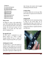
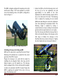
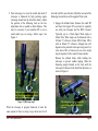
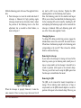
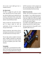
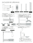
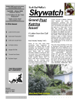
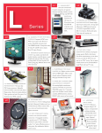
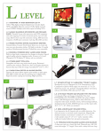
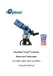
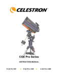
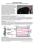
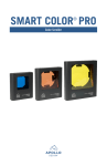
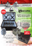
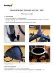
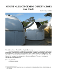
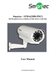
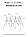
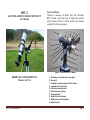
DSV-2
ALTITUDE-AZIMUTH TELESCOPE MOUNT
User Manual
Your New Mount
Thanks for choosing the Desert Sky Astro Products
DSV-2 mount. Take some time to familiarize yourself
with its features (Figure 1). Please read the user manual
completely before using mount.
12
11
10
9
20
18
19
13
17
5
6
16
8
15
7
14
4
3
2
1
Figure 1: Parts of the DSV-2 mount
DESERT SKY ASTRO PRODUCTS
Phoenix, AZ, USA
DSV-2 User Manual Rev -
1) Mounting socket (underside of base plate)
2) Base plate
3) Azimuth bearing housing & built-in column
4) Azimuth slow motion knob
5) Altitude slow motion knob
6) Altitude bearing housing
7) Panning handle
8) Right side dovetail clamp
9) Right side dovetail clamp knob
10) Altitude brake
Page 1
11) Bubble level
12) Left side dovetail clamp knob
13) Left side dovetail clamp
14) Left side dovetail clamp set screws (3)
15) QBS adjustment plate
16) QBS balancing weight
17) QBS balancing track
18) QBS adjustment plate slots (2)
19) QBS adjustment knobs (2)
20) QBS short dovetail adapter
Package contents
The shipping box contains a fully assembled DSV-2
mount, a fully assembled Quick Balance System (QBS)
unit, Velcro dot balance point markers, a Velcro strip and
wrenches. Other items may be present in the box
depending on your specific order. Please remove
protective wrapping prior to use.
mount, telescopes and accessories used and equipped
with mounting bolt that matches the mount.
Leveling the Mount
Use the built-in bubble level to level the mount. While
perfect leveling is not required, an out of level mount will
not perform well.
Attaching the QBS
The QBS attaches to the left or right side dovetail clamp
by sliding the short dovetail adapter into the
corresponding dovetail clamp, as shown in Figure 2. To
facilitate installation, place the balancing weight so that it
is aligned with the altitude axis. Tighten dovetail knob to
secure QBS in place.
Recommended Payload
The DSV-2 mount is recommended for use with
Refractor telescopes up to 102mm f/7, SchmidtCassegrain telescope (SCT) up to 8” aperture and
Maksutov-Cassegrain telescope (MCT) up to 6” aperture.
Attaching mount to a tripod
The mount attaches to a tripod (sold separately) by
threading the tripod’s mounting screw onto the mount
mounting socket. Recommended tripods are Desert Sky
Astro Products Surveyor-Style Tripod or any heavy duty
tripod capable of supporting the combined weight of the
DSV-2 User Manual Rev -
Figure 2: Attaching the QBS
Page 2
The QBS is shipped configured for mounting to the right
side dovetail clamp. If left side installation is desired,
reverse the balancing track so the QBS is configured as
shown in Figure 3.
Figure 3: QBS in left side clamp configuration
Attaching a telescope and setting up QBS
QBS must be setup prior to operating the mount. Proper
balancing of the altitude axis is essential for the correct
operation of the DSV-2 mount.
Prepare the telescope to be used with the mount by
installing the star diagonal, finder, tube rings and the
lightest eyepiece you will regularly use. The telescope
must be equipped with a Vixen-style dovetail bar adapter
in order to be attached to the DSV-2 mount. Prepare the
QBS by applying the supplied Velcro strip to the top
edge of the balancing track.
DSV-2 User Manual Rev -
1. Adjust the QBS so that the balancing track is all
the way up on the rear adjustment slot and
approximately in the middle of the front
adjustment slot, and the balancing weight is all the
way to the back end of the track. The balancing
track is adjusted by loosening the two knurled
QBS knobs and sliding the track on the adjustment
slots, then tightening the adjustment knobs. The
balancing weight is adjusted by turning it
counterclockwise to loosen, sliding it to the desired
position and turn weight clockwise to set in place.
Insert the telescope and slide the telescope back or
forth on the dovetail clamp (or the telescope on the
tube rings) to balance the telescope in the
front/back direction as shown in Figure 4. Tighten
dovetail clamp knob once telescope is balanced.
Small EP
Velcro strip
Slide telescope back or forth to balance,
tighten dovetail clamp knob after balancing.
Balancing weight all the way back and balancing
track all the way up on adjustment slot.
Figure 4: QBS setup step 1
Page 3
2. Point telescope at or near the zenith and check if
telescope is balanced for high pointing angles
(telescope should not tip forward or back). Adjust
the position of the balancing track on the rear
adjustment slot as needed to obtain balance. This
may be necessary if your smallest EP is not so
small and/or you are using a finder scope. See
Figure 5.
Small EP
not tend to drift in any direction. Mark the rear end of the
balancing track with one of the supplied Velcro dots
3. Engage the altitude brake. Remove the small EP
and insert the largest EP you intend to regularly
use with your telescope and the DSV-2 mount.
Typically, up to a 35mm Super Wide Angle or
26mm Ultra Wide Angle can be balanced with a
102mm f/7 refractor (41mm SWA/31mm UWA
with an 80mm F/7 refractor), although this will
depend on the particular telescope being used. For
extra heavy EPs or binoviewers an extra weight
may be required. Call or email for more details.
Release the altitude brake while holding the
telescope to prevent sudden tipping. Slide the
balancing weight forward on the track until the
telescope is balanced in the back/front direction, as
shown in Figure 6.
Large EP
Slide rear end of balancing track on
the rear adjustment slot to balance
scope at high pointing angles
Figure 5: QBS setup step 2.
When the telescope is properly balanced, it takes the
same amount of force to swing it up or down and it will
Slide balancing weight forward until
scope is balanced in the front/back
direction.
Figure 6: QBS setup step 3
DSV-2 User Manual Rev -
Page 4
Mark the balancing point with one of the supplied Velcro
dots.
4. Point telescope at or near the zenith and check if
telescope is balanced for high pointing angles
(telescope should not tip forward or back). Adjust
the position of the balancing track on the front
adjustment slot as needed to obtain balance, as
shown in Figure 7.
not tend to drift in any direction. Tighten the QBS
adjusting knobs to set the balancing track in place.
Once the balancing points for the smallest and largest
EPs in your set have been identified, the balancing points
for the remaining EPs can be found by installing the EP
and adjusting the balancing weight on the track until the
telescope is balanced. Mark each balancing point with
one of the Velcro dots supplied (5 total).
Changing Eyepieces
To change EPs during an observing session, engage the
altitude brake, remove the current EP, the install the new
EP and move the balancing weight to the balancing point
corresponding to the new EP. Then release the altitude
brake to continue observing.
Large EP
Slide balancing track on the front
adjustment slot to balance scope at
high pointing angles
Figure 7: QBS setup step 4
When the telescope is properly balanced, it takes the
same amount of force to swing it up or down and it will
DSV-2 User Manual Rev -
Removing the telescope
If you remove the telescope for storage at the end of the
observing session, put an indexing mark (small piece of
tape or crayon mark) on the telescope’s dovetail bar to
record its position with respect to the dovetail clamp.
This way you will not need to setup the QBS again when
the telescope is reinstalled on the mount.
Removing the QBS
The QBS can be removed for mount transportation or
storage. Put an indexing mark (small piece of tape or
crayon mark) on the QBS dovetail adapter to record its
position with respect to the dovetail clamp. This way you
Page 5
will not need to setup the QBS again when it is
reinstalled on the mount.
Slow Motion Controls
The DSV-2 is equipped with geared slow motion
controls. Slip clutches allow the slow motion controls to
move the mount without the need to unlock/lock the axes
for slewing. A small amount of friction is used to transfer
the slow motion control inputs to the mount (hence the
importance of properly balancing the mount).
Turning the altitude slow motion knob clockwise will
move the telescope towards the zenith and
counterclockwise will move the telescope move the
telescope towards the horizon.
the DSV-2 mount makes it ideal for scanning the sky
with a short focal length telescope. The handle can be
removed by unthreading it from the dovetail clamp.
Double Telescope Operation
The DSV-1 can be used with two telescopes in a side by
side configuration. To use in double telescope mode, at
least one of the scopes must be equipped with tube rings.
In this mode, the QBS (with the short dovetail adapter
removed) in attached to the top holes of the tube rings of
one of the scopes, as shown in Figure 8.
It is preferable to attach the QBS to the lighter of the two
telescopes being used, for better Azimuth axis balance.
Follow the steps listed in the “setting up QBS” section to
setup QBS for double telescope use.
Turning the azimuth slow motion clockwise will move
the telescope to the right (clockwise as seen from the top)
and counterclockwise moves the telescope to the left.
The slow motion controls are adjusted at the time the
mount is assembled. No adjustments are needed during
normal use. If you believe the slow motion controls in
your mount need adjustment, please email for further
instructions.
Panning Handle
A panning handle is provided standard with the DSV-2
mount. It can be used for slewing the mount and pointing
the telescope. The panning handle and lock-less design of
DSV-2 User Manual Rev -
Figure 8: Setup for double telescope operation
Page 6
Aligning the two dovetail clamps
For double telescope operation, you may want to align
the two dovetail clamps so the two scopes point at the
same object. Because the alignment between the optical
tube and dovetail bar varies from telescope to telescope,
alignment of the dovetail clamps must be made with the
actual telescopes to be used. Alignment is more easily
done during the day. Find a distant, easily visible object
(i.e. a power transmission tower).
WARNING:
NEVER POINT TELESCOPES AT OR NEAR THE SUN.
DAMAGE TO THE EYES AND/OR THE INSTRUMENT
MAY OCCUR.
Perform the following steps:
1. Remove the QBS if it is attached to the mount.
2. Mount a telescope (with star diagonal, EPs, etc
attached) on the dovetail clamp on which you
intend to use the telescope (for example, if you
intend to use a refractor on the left side and a
Maksutov on the right side, they should be
mounted to that side during alignment).
3. Roughly balance the scopes by sliding back or
forth on the dovetail clamps as needed, tighten the
dovetail clamp knobs.
4. Point the mount to the object chosen and center it
in the field of view of the right side telescope.
5. Engage the altitude brake tightly.
6. Loosen slightly the left side dovetail clamp
setscrew (located on the underside of the clamp).
DSV-2 User Manual Rev -
7. Rotate up or down the left side telescope on the
altitude axis as needed so the object is centered in
up/down direction in the field of view of the left
hand telescope (object may not be centered in the
left/right direction, this will be corrected in the
following steps).
8. Tighten the left side dovetail clamp setscrew.
9. Release the altitude brake.
10.Center (up/down and left/right) the alignment
object in the field of view of the left side telescope.
Object should be centered in the up/down direction
in the field of view of the right side telescope. If
not, repeat steps 4-8.
11. Engage the altitude brake.
12. On the right side dovetail clamp, loosen the front
setscrew (located next to the panning handle) and
back setscrew (located opposite the panning
handle).
13. Tighten the front or back dovetail clamp setscrew
as needed to center the object in the left/right
direction of the right side telescope. Which
setscrew to tighten will depend on the type of
telescope and type of diagonal (star or correct
image) used.
14. Once the object is centered in both directions in
the field of view of both scopes, tighten the
setscrews.
15. Reinstall QBS as needed for single telescope or
double telescope operation.
Page 7
Alignment Notes:
a. If you notice after aligning the dovetail clamps that
the friction in the altitude axis has increased or
decreased compared to the original setting, it can
be adjusted by tightening or loosening either side
dovetail clamp cap screw (located on the center of
the face of the dovetail clamp, scopes must be
removed to perform this adjustment). Only a small
adjustment is needed, work in small increments
until the original setting is restored. The amount of
friction in the altitude axis must be equal to that in
the azimuth axis and just enough for the slow
motion controls to operate. If in doubt, email us for
further instructions.
b. The right side dovetail setscrews offer a limited
adjustment range. Prior to attempting to align the
dovetail clamps, make sure the dovetail bar is
aligned with the optical tube. If the misalignment
between the dovetail bar and optical tube is too
large, alignment of the views may not be possible.
Mount Care
Store mount protected from the elements. If the mount
becomes wet or soiled during use, wipe water or dirt with
clean lint-free cloth and allow it to dry indoors. All
bearings and moving parts have been lubricated at
manufacture and do not require further lubrication during
use.
The mount is not intended to be disassembled or serviced
by user. Please call or email if mount needs service.
Warranty and Service
Your mount is guaranteed to be free of material and
workmanship defects for one year from date of original
purchase. Within this period of time, Desert Sky Astro
Products will repair or replace at its discretion any
defective components. This is the only and exclusive
warranty offered. Abuse, accidental damage and
unauthorized modifications & repairs are not covered by
the warranty.
To obtain service, please call 602-550-4331 or email
[email protected] to make return arrangements.
©2011 Desert Sky Astro Products.
c. The alignment of the dovetail clamps is specific
for the scopes used during the alignment process.
If you later switch to different scopes, the views
may not be aligned (due to differences in the
alignment between the telescope’s optical tube and
dovetail bar). Repeat alignment process for the
new telescopes, if desired.
DSV-2 User Manual Rev -
Page 8