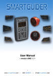
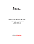
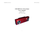
1
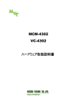
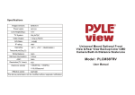
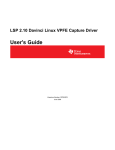
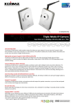
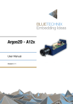
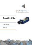
Image Sensor Demo System Kits
Introduction
Image Sensor Demo System Kits
Introduction
The Micron® Imaging demonstration system family supports the full line of Micron’s
CMOS image sensor products. The current demonstration system is called the DEMO2,
which uses the USB 2 interface to transport raw digital video data from the sensor to the
host PC. Several software applications are provided with the demonstration system to
enable the user to display the data from the sensor on the host computer, and to change
some basic settings of the sensor for evaluation purposes. A software development kit
(SDK) is also provided to customers who wish to write their own software applications to
access the sensor on the demo system.
The front board contains the lens and the imaging sensor. The back board contains the
USB 2 controller and is called the DEMO2 board (shown in Figure 1).
Figure 1:
Demo Board and Sensor Headboard
Hardware Requirements
• Pentium III 450 MHz or higher (a faster processor will improve the displayed frame
rate on the PC)
• 128MB RAM
• USB 2.0 Host controller (we recommend Adaptec’s “USB 2 CONNECT” PCI USB2
adapter and their part number is AUA-3100LP and AUA-1420A for notebook PCs)
PDF: 09005aef82ca4ad2/Source: 09005aef82ca8484
demobrief.fm - Rev. B 7/07 EN
1
Micron Technology, Inc., reserves the right to change products or specifications without notice.
©2006 Micron Technology, Inc. All rights reserved.
Products and specifications discussed herein are for evaluation and reference purposes only and are subject to change by
Micron without notice. Products are only warranted by Micron to meet Micron’s production data sheet specifications. All
information discussed herein is provided on an “as is” basis, without warranties of any kind.
Image Sensor Demo System Kits
Introduction
Software Requirements
• Windows 2000 with a minimum of Service Pack 2 or Windows XP with a minimum of
Service Pack 1
• The latest drivers for the USB 2.0 host controller
Note:
We do not recommend Windows 2000 with built-in USB2 controllers.
Demonstration System Contents
•
•
•
•
•
•
Figure 2:
Micron Imaging demo camera board
Micron sensor head with lens
USB 2.0 cable
Software CD
Demo user manual
Camera tripod
C-Mount, S-Mount, and Mini Lens with a Lens Evalulation Adapter
C-Mount
PDF: 09005aef82ca4ad2/Source: 09005aef82ca8484
demobrief.fm - Rev. B 7/07 EN
S-Mount
2
Mini Lens
Micron Technology, Inc., reserves the right to change products or specifications without notice.
©2006 Micron Technology, Inc. All rights reserved.
Image Sensor Demo System Kits
Product Matrix
Product Matrix
Below is a list of our products with their available lens type. Note that the DEMO2 board
is able to run at the full clock speed for each sensor, although it is also possible to run at
slower clock speeds. Refer to the ordering info for part numbers and ordering information.
Table 1:
Product Matrix
Sensor
Lens Type
SOC
C-Mount
MT9V011
√
√
√
MT9M011
MT9T012
S-Mount
Mini Lens with a Lens
Evaluation Adapter
MT9V111
MT9V131
√
MT9V112
√
√
MT9V125
MT9V135
MT9M1111
MT9M131
√
√
√
√
√
√
√
√
MT9M112
MT9D111
MT9D131
MT9D112
Non-SOC
C-Mount
MT9V011
√
√
√
√
√
√
√
√
MT9V022
MT9V032
MT9M001
MT9M011
MT9D011
MT9T001
MT9T031
MT9P031
Notes:
PDF: 09005aef82ca4ad2/Source: 09005aef82ca8484
demobrief.fm - Rev. B 7/07 EN
Mini Lens with a Lens
Evaluation Adapter
√
√
√
√
MT9T012
MT9P001
S-Mount
√
√
1. DEMO2 can only support a maximum of 47 MHz oscillators even though the nominal clock
for the MT9M111 is 54 MHz.
3
Micron Technology, Inc., reserves the right to change products or specifications without notice.
©2006 Micron Technology, Inc. All rights reserved.
Image Sensor Demo System Kits
Operational Description
Operational Description
Board Functionality
The USB board provides centralized communication between the image sensor and the
host PC. The system receives firmware programming from a serial EEPROM that configures the board into a synchronous slave FIFO mode. The sensor data fills up an internal
FIFO with data when the elimination of handshake is taking place. The firmware automatically sends data through the USB 2.0 interface whenever the FIFO becomes full and
the FRAME_VALID is polled to determine when a frame is complete. When the
FRAME_VALID drops, the host computer is signaled through the USB interface with a
frame end packet. The firmware also supplies the necessary code to implement USB
vendor commands that allow the host computer to query and modify the system configuration data.
Vendor commands are used to communicate with the image sensor through the serial
host interface protocol built into the sensor head interface.
Figure 3:
DEMO2 Board Block Diagram
FPGA
26-Pin
Sensor Head
Connector
10
Input
Buffer
30
30
RAM
Controller
WR Control
PIXCLK
LINE_VALID
FRAME_VALID
Output
Buffer
16
USB
Controller
Chip
USB
Channel
to PC
RD Control
USB
Controller
Sync.
Timing
Generator
FX_FULL
LINE_OUT
FRAME_OUT
IF_CLOCK
Sensor
Interface
Program
Download
JTAG
EEPROM
32
Microm
Low-Power
SDRAM
DEMO2
Micron’s DEMO2 board comes equipped with the addition of an FPGA and memory
controller. This allows the hardware to store up to three entire frames of data on the
board prior to USB 2 transport, which is important for large resolution sensors to avoid
dropping frames. The DEMO2 baseboards are common to all sensor configurations. The
FPGA optimizes the data flow through the USB, such that the FIFOs never overflow and
complete frames are guaranteed even for large sensors.
PDF: 09005aef82ca4ad2/Source: 09005aef82ca8484
demobrief.fm - Rev. B 7/07 EN
4
Micron Technology, Inc., reserves the right to change products or specifications without notice.
©2006 Micron Technology, Inc. All rights reserved.
Image Sensor Demo System Kits
Ordering Information
Ordering Information
For ordering information, contact your local sales representative at micron.com/
purchasing.
Table 2:
Part Number Ordering
SOC
MT9V111
MT9V112
MT9V125
MT9M1111
MT9M112
MT9M113
MT9D111
MT9D112
MT9D131
MT9M131
MT9V135
MT9V131
MT9V113
Non-SOC
MT9V011
MT9V013
MT9V022
MT9M001
MT9M019
MT9D011
MT9D012
PDF: 09005aef82ca4ad2/Source: 09005aef82ca8484
demobrief.fm - Rev. B 7/07 EN
Part Numbers
Kit Description
MT9V111I99STCD ES
MT9V111I99STCH ES
MT9V112I2ASTCD ES
MT9V112I2ASTCH ES
MT9V125IA7XTCD ES
MT9V125IA7XTCH ES
MT9M111P12STCD ES
MT9M111P12STCH ES
MT9M112PA3STCD ES
MT9M112PA3STCH ES
MT9M113PACSTCD ES
MT9M113PACSTCH ES
MT9D111I93STCD ES
MT9D111I93STCH ES
MT9D112I93STCD ES
MT9D112I93STCH ES
MT9D131C12STCD ES
MT9D131C12STCH ES
MT9M131C12STCD ES
MT9M131C12STCH ES
MT9V135C12STCD ES
MT9V135C12STCH ES
MT9V131C12STCD ES
MT9V131C12STCH ES
MT9V113PACSTCD ES
MT9V113PACSTCH ES
MT9V111 color VGA complete demo kit
MT9V111 color VGA demo head board
MT9V112 color VGA complete demo kit
MT9V112 color VGA demo head board
MT9V125 color VGA complete demo kit (auto)
MT9V125 color VGA demo head board (auto)
MT9M111 color 1.3Mp complete demo kit
MT9M111 color 1.3Mp demo head board
MT9M112 color 1.3Mp complete demo kit
MT9M112 color 1.3Mp demo head board
MT9M113 color 1.3Mp complete demo kit
MT9M113 color 1.3Mp demo head board
MT9D111 color 2Mp complete demo kit
MT9D111 color 2Mp demo head board
MT9D112 color 2Mp complete demo kit
MT9D112 color 2Mp demo head board
MT9D131 color 2Mp complete demo kit
MT9D131 color 2Mp demo head board
MT9M131 color 1.3Mp complete demo kit
MT9M131 color 1.3Mp demo head board
MT9V135 color VGA complete demo kit
MT9V135 color VGA demo head board
MT9V131 color VGA complete demo kit
MT9V131 color VGA demo head board
MT9V113 color VGA complete demo kit
MT9V113 color VGA demo head board
Part Numbers
Kit Description
MT9V011P11STCD ES:B
MT9V011P11STCH ES:B
MT9V013PACSTCDM ES
MT9V013PACSTCHM ES
MT9V013PACSTCDP ES
MT9V013PACSTCHP ES
MT9V022I77ATMD ES
MT9V022I77ATMH ES
MT9V022I77ATCD ES
MT9V022I77ATCH ES
MT9M001C12STMD ES
MT9M001C12STMH ES
MT9M019IA9STCD ES
MT9M019IA9STCH ES
MT9D011I29STCD ES
MT9D011I29STCH ES
MT9D012IA3STCD ES
MT9D012IA3STCH ES
MT9V011 color VGA complete demo kit
MT9V011 color VGA demo head board
MT9V013 color VGA complete demo kit (MIPI added)
MT9V013 color VGA demo head board (MIPI added)
MT9V013 color VGA complete demo kit (CCP added)
MT9V013 color VGA demo head board - (CCP added)
MT9V022 monochrome VGA complete demo kit (auto)
MT9V022 monochrome VGA demo head board (auto)
MT9V022 color VGA complete demo kit (auto)
MT9V022 color VGA demo head board (auto)
MT9M001 monochrome SXGA complete demo kit
MT9M001 monochrome SXGA demo head board
MT9M019 color 1.3Mp complete demo kit
MT9M019 color 1.3Mp demo head board
MT9D011 color 2Mp complete demo kit
MT9D011 color 2Mp demo head board
MT9D012 color 2Mp complete demo kit
MT9D012 color 2Mp demo head board
5
Micron Technology, Inc., reserves the right to change products or specifications without notice.
©2006 Micron Technology, Inc. All rights reserved.
Image Sensor Demo System Kits
Ordering Information
Table 2:
Part Number Ordering (continued)
MT9T001
MT9T012
MT9P011
MT9P001
MT9P031
MT9T013
MT9T031
MT9P401
MT9P012
MT9V032
Notes:
MT9T001P12STCD ES
MT9T001P12STCH ES
MT9T012IA3STCD ES:C
MT9T012IA3STCH ES:C
MT9P011I12STCD ES
MT9P011I12STCH ES
MT9P001I12STCD ES:B
MT9P001I12STCH ES:B
MT9P031I12STCD ES
MT9P031I12STCH ES
MT9T013PACSTCDM ES
MT9T013PACSTCHM ES
MT9T013PACSTCDP ES
MT9T013PACSTCHP ES
MT9T031P12STCD ES
MT9T031P12STCH ES
MT9P401I12STCD ES
MT9P4011I12STCH ES
MT9P012PACSTCDM ES
MT9P012PACSTCHM ES
MT9P012PACSTCDP ES
MT9P012PACSTCHP ES
MT9V032C12STCD ES
MT9V032C12STCH ES
MT9V032C12STMD ES
MT9V032C12STMH ES
MT9T001 color 3Mp complete demo kit
MT9T001 color 3Mp demo head board
MT9T012 color 3.1Mp complete demo kit
MT9T012 color 3.1Mp demo head board
MT9P011 color 5Mp complete demo kit - 22° shift
MT9P011 color 5Mp demo head board - 22° shift
MT9P001 color 5Mp complete demo kit - 7° shift
MT9P001 color 5Mp demo head board - 7° shift
MT9P031 color 5Mp complete demo kit - 7° shift
MT9P031 color 5Mp demo head board - 7° shift
MT9T013 color 3Mp complete demo kit (MIPI)
MT9T013 color 3Mp demo head board (MIPI)
MT9T013 color 3Mp complete demo kit (CCP)
MT9T013 color 3Mp demo head board (CCP)
MT9T031 color 3Mp complete demo kit
MT9T031 color 3Mp demo head board
MT9P401 color 5Mp HD complete demo kit
MT9P401 color 5Mp HD demo head board
MT9P012 color 5Mp complete demo kit (MIPI)
MT9P012 color 5Mp demo head board (MIPI)
MT9P012 color 5Mp complete demo kit (CCP)
MT9P012 color 5Mp demo head board (CCP)
MT9V032 color VGA complete demo kit
MT9V032 color VGA demo head board
MT9V032 monochrome VGA complete demo kit
MT9V032 monochrome VGA demo head board
1. DEMO2 can only support a maximum of 47 MHz oscillators even though the nominal clock
for the MT9M111 is 54 MHz.
®
8000 S. Federal Way, P.O. Box 6, Boise, ID 83707-0006, Tel: 208-368-3900
[email protected] www.micron.com Customer Comment Line: 800-932-4992
Micron, the M logo, the Micron logo, and DigitalClarity are trademarks of Micron Technology, Inc. All other trademarks are the property of
their respective owners. Micron Technology, Inc. All rights reserved. All information is provided “AS IS,” without warranties of any kind,
and is subject to change without notice.
PDF: 09005aef82ca4ad2/Source: 09005aef82ca8484
demobrief.fm - Rev. B 7/07 EN
6
Micron Technology, Inc., reserves the right to change products or specifications without notice.
©2006 Micron Technology, Inc. All rights reserved.