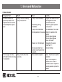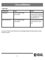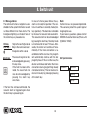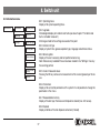
1
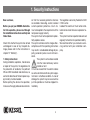
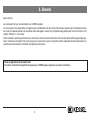
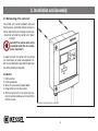
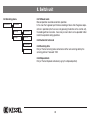
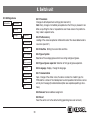
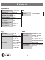
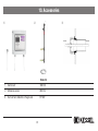
INSTALLATION, OPERATION AND MAINTENANCE INSTRUCTIONS
Grease layer thickness measuring device SonicControl
Product Advantages
Measurement, display and control of the depth of the grease layer
Free of charge download software available at www.kessel.de
Ultrasonic sensor for precision measurement accurate to centimetres
Monitoring of wastewater temperature in the separator
Protective rating ultrasonic probe IP 68
Battery-buffered alarm in the event of power failure
Can be combined with all KESSEL grease separators
Easy installation (inc. installation set)
Picture shows No. 917821
Installation
Service
of this unit should be carried out by a licensed professional servicer:
Company / Telephone No.
Edition::
01/2012
Number:
395-016EN
Subject to technical amendments
Contents
1. Safety Instructions
.......................................................................................................... Page
4
2. General
.......................................................................................................... Page
5
3. Installation and Assembly
3.1
3.2
3.3
3.4
Installation of the switch unit ...............................................
Installation of sensor and sensor bracket ............................
Installation dimensions of sensor ........................................
Installation suggestion .........................................................
Page
Page
Page
Page
6
7
8
10
4. Electrical connection
4.1
4.2
4.3
4.4
4.5
External signal generator .....................................................
Shortening the control cable................................................
Potential-free switch contact ...............................................
Installation / cable connection .............................................
Connection diagram ............................................................
Page
Page
Page
Page
Page
14
14
14
15
18
5. Operation
5.1 .......Making the plant ready for operation................................... Page
5.2
Duties of the user................................................................. Page
5.3
Instruction / Handover ......................................................... Page
19
19
19
6. Treatment/Maintenance
.......................................................................................................... Page
20
7. Errors and Malfunction
7.1
7.2
7.3
7.4
......Incident display....................................................................
......Fault display.........................................................................
......General faults.......................................................................
......System faults .......................................................................
Page
Page
Page
Page
21
22
24
25
8. Switch unit
8.1 ......Menu navigation ..................................................................
8.2 ......System menu .......................................................................
8.3 ......Information menu.................................................................
8.3.1 ...Operating hours ...................................................................
8.3.2 ...Log book..............................................................................
Page
Page
Page
Page
Page
26
26
27
27
27
2
Contents
8.3.3 ...Control unit type ..................................................................
8.3.4 ....Servicing date ......................................................................
8.3.5 ...Current measured values.....................................................
8.3.6 ...Parametersr .........................................................................
8.3.7 ....Measured data memory.......................................................
8.3.8 ...Disposal ...............................................................................
8.4 ......Servicing menu ....................................................................
8.4.1 ....Manual mode .......................................................................
8.4.2 ...Test mode ............................................................................
8.4.3 ...Servicing dates ....................................................................
8.4.4 ....Disposal date .......................................................................
8.5 ......Settings menu......................................................................
8.5.1 ...Parameters ..........................................................................
8.5.2 ....Profile memory.....................................................................
8.5.3 ...Date/time .............................................................................
8.5.4 ....Type of system.....................................................................
8.5.5 ....Type of grease separator .....................................................
8.5.6 ...Language .............................................................................
8.5.7 ...Communication ...................................................................
8.5.8 ....Sensors................................................................................
8.5.9 ...Reset....................................................................................
Page
Page
Page
Page
Page
Page
Page
Page
Page
Page
Page
Page
Page
Page
Page
Page
Page
Page
Page
Page
Page
27
27
27
27
27
27
28
28
28
28
28
29
29
29
29
29
29
29
29
29
29
9. Technical data
.......................................................................................................... Page
30
10. Assessories
.......................................................................................................... Page
31
11. Declaration of Conformity
.......................................................................................................... Page
32
12. Guarantee
.......................................................................................................... Page
33
13. Handover Ceritficate
.......................................................................................................... Page
34
3
1. Security Instructions
Dear customer,
Before you put your KESSEL SonicControl into operation, please read through
the installation instructions carefully and
follow them.
Check first whether the system has arrived
undamaged. In case of any transport damage, please refer to the instructions in
chapter 12 "Warranty".
1. Safety instructions:
During installation, operation, maintenance
or repair of the system, the regulations for
the prevention of accidents, the pertinent
DIN and VDE standards and directives, as
well as the directives of the local power supply industry must be heeded.
Before putting the device into operation,
make sure through professional examinati-
on that the necessary protective features
are available. Grounding, neutral, residual
current-operated protective circuit etc.
must correspond to the requirements of the
local power supply industry.
The system must not be operated in potentially explosive areas.
The system contains electric charges. Noncompliance with the operating instructions
may result in considerable damage to property, personal injuries or even fatal accidents.
The system must be disconnected
from the mains before any work is
carried out on it.
It must be ensured that the electric cables
as well as all other electrical system equipment are in a faultless condition. In case of
damage, the system may on no account be
put into operation or must be stopped immediately.
4
The regulations set out by the directive VDE
0100 must be
heeded. The switch unit must not be installed in rooms where there is an explosion hazard.
The system must be inspected and serviced
regularly to maintain its operational ability.
We recommend that you conclude a servicing contract with your installation company.
2. General
Dear customer,
we are pleased that you have decided to buy a KESSEL product.
The entire system was subjected to a stringent quality control before it left our factory. Nevertheless, please check immediately whether
the system has been delivered to you complete and undamaged. In case of any transport damage, please refer to the instructions in the
chapter “Warranty” in this manual.
These installation, operating and maintenance instructions contain important information that has to be observed during assembly, operation, maintenance and repair. Prior to carrying out any work on the system, the operator and the responsible technical personnel must
carefully read and heed these installation and operating instructions.
Areas of application for the switch unit:
The switch unit monitors the depth of the grease layer in KESSEL grease separators accurate to centimetres.
5
3. Installation and Assembly
3.1 Wall mounting of the control unit
The control unit must be installed in a dry and
frost free area – preferable indoors where any
alarms and control unit message can be seen
/ heard. Do not install the control unit in direct
sunlight!
Caution!!!! The control unit is not to
be installed inside the oil or coalescence separator!!!
In order to mount the control unit the control
unit cover does not need to be opened. Predrill 2 x 6mm diameter holes 168mm apart (use
the drilling template if required)
Installation:
1. Drill two holes
2. Insert two dowels
3. Screw in two screws to proper depth
4. Hang control unit on two screws
5. Affix the control unit on the screws by pushing the control unit down until it seat firmly
on both screws.
Illustration of SonicControl control unit
6
3. Installation and Assembly
3.2 Installation of sensor and sensor bracket
➊
➋
➌
➍
Place the drilling template on the outside of the outlet structure and drill 2 x Ø 5,5 mm holes
(top two holes!).
Place the drilling template on the inside of the outlet structure and fix in place from the outside (see ).
Put the sensor and the pipe clamps together to the sensor bracket.
Screw the sensor bracket to the outlet structure using a torque of 1 Nm
and clip the sensor in place (see page 10).
7
sensor bracket
PT screw Torx 40x12
PT screw Torx K 50x20
Pipe clamp PE d25
Drilling template/ screw cover
Outlet structure partition
SonicControl sensor
Red arrow marking
3. Installation and Assembly
3.3 Installation dimensions of sensor
free standing
Freie Aufstellung
Article No.
Artikel
EURO "G"
93002
93004
93007
93010
EURO "D"
93002.00 / D1
93004.00 / D1
93007.00 / D1
93010.00 / D1
EURO "DS"
93002.50 und .00 / DS1
93004.50 und .00 / DS1
93007.50 und .00/ DS1
93010.50 und .00 / DS1
EURO E+S "M"
93002.50 und .00 / M1
93004.50 und .00 / M1
93007.50 und .00 / M1
93010.50 und .00 / M1
EURO E+S "PV"
93002.50 und .00 / P1
93004.50 und .00 / P1
93007.50 und .00 / P1
93010.50 und .00 / P1
DIN 4040 "G" rund
98201
98202
DIN 4040 "D" rund
98201.00/D1
98202.00/D1
Alarm
level
Alarmniveau
=
=max.
max. grease
layer thickness
Fettschichtin cm
dicke in cm
Recommended
prelimi- max. sludge layer
empfohlenes Vornary
alarm level
cm
alarmniveau
inincm
(= 2/3 of the max. stora- in cm ( = 50% of
(=
2/3
des
max.
ge volume)
sludgetrap volume)
Speichervolumens)
2
4
7
10
Distance
the
Abstand between
Oberkannte
upper edge of the
unterer
"Finger"
zu
lower “finger” and the Drill holes in
Bohrlöcher
in
Unterkannte
Auslauf
template
lower
edge of the
outlet drilling
(water
line)
Bohrschablone
(Wasserlinie)
obere beiden Bohrlöcher
50 cm
obere
beiden
Top
two
drill Bohrlöcher
holes
50 cm
obere
beiden
Top
two
drill Bohrlöcher
holes
50 cm
obere
beiden
Top
two
drill Bohrlöcher
holes
50 cm
obere
beiden
Top
two
drill Bohrlöcher
holes
23
24
27
24
15
16
18
16
20
25
30
27
2
4
7
10
50 cm
50 cm
50 cm
50 cm
obere
beiden
Top
two
drill Bohrlöcher
holes
obere
beiden
Top
two
drill Bohrlöcher
holes
obere
beiden
Top
two
drill Bohrlöcher
holes
obere
beiden
Top
two
drill Bohrlöcher
holes
23
24
27
24
15
16
18
16
20
25
30
27
2
4
7
10
50 cm
50 cm
50 cm
50 cm
Top
two
drill Bohrlöcher
holes
obere
beiden
Top
two
drill Bohrlöcher
holes
obere
beiden
Top
two
drill Bohrlöcher
holes
obere
beiden
Top
two
drill Bohrlöcher
holes
obere
beiden
23
24
27
24
15
16
18
16
20
25
30
27
2
4
7
10
50 cm
50 cm
50 cm
50 cm
Top
two
drill holes
obere
beiden
Bohrlöcher
Top
two
drill holes
obere
beiden
Bohrlöcher
Top
two
drill holes
obere
beiden
Bohrlöcher
Top
two
drill holes
obere
beiden
Bohrlöcher
23
24
27
24
15
16
18
16
20
25
30
27
2
4
7
10
50 cm
50 cm
50 cm
50 cm
Top
two
drill holes
obere
beiden
Bohrlöcher
Top
two
drill holes
obere
beiden
Bohrlöcher
Top
two
drill holes
obere
beiden
Bohrlöcher
Top
two
drill holes
obere
beiden
Bohrlöcher
23
24
27
24
15
16
18
16
20
25
30
27
1
2
58 cm
58 cm
Top
two drill holes
obere beiden Bohrlöcher
Top
two drill holes
obere beiden Bohrlöcher
16
16
11
11
46
54
1
2
58 cm
58 cm
Top
two
drill Bohrlöcher
holes
obere
beiden
Top
two
drill Bohrlöcher
holes
obere
beiden
16
16
11
11
14
23
NS
NS
8
3. Installation and Assembly
Installation dimensions of sensor
Underground
Installtaion
Article No.
93002 / 80 / 120 B und D
93004 / 80 / 120 B und D
93007 / 120 B und D
93010 / 120 B und D
93015 / 120 B und D
93020 / 120 B und D
DIN 4040 "G"
98201 / 00 / 80 / 120 B und D
98202 / 00 / 80 / 120 B und D
98204 / 00 / 80 / 120 B und D
NS
Distance between the
upper edge of the
lower “finger” and the
lower edge of the outlet
(water line)
Drill holes in
drilling template
Alarm level
= max. grease
layer thickness
in cm
max. sludge layer
Recommended
preliminary
alarm level in cm in cm ( = 50% of
(= 2/3 of the max. sludgetrap volume)
storage volume)
2
4
7
10
15
20
50 cm
50 cm
48 cm
48 cm
56 cm
56 cm
obere
beiden
Bohrlöcher
Top
two
drill holes
Top
two
drill holes
obere
beiden
Bohrlöcher
untere
Bohrlöcher
Top
twobeiden
drill holes
untere
Bohrlöcher
Top
twobeiden
drill holes
untere beiden
Bohrlöcher
Bottom
two drill
holes
untere beiden
Bohrlöcher
Bottom
two drill
holes
17
17
17
17
17
17
11
11
11
11
11
11
15
27
23
23
32
31
1
2
4
58 cm
58 cm
58 cm
Bottom
two drill
holes
untere beiden
Bohrlöcher
Bottom
two drill
holes
untere beiden
Bohrlöcher
Bottom
two drill
holes
untere beiden
Bohrlöcher
16
16
16
11
11
11
46
54
54
F
Note:
For more articles please contact the KESSEL customer service.
After installation completely fill the separator with water, check height and correct if necessary!
Completely filled separator must perform the "manual mode" (2.1.) SonicControl "0 cm" show.
Should be no mechanical correction possible change in "Parameters -> level adjustment"(3.1.7) to perform.
The parameters are password protected - please contact the KESSEL customer service at +49 (0) 8456/27462.
9
3. Installation and Assembly
3.4 Installation suggestion
Cable entry for
SonicControl®
Grease separator < NS 15
Tank wall < = 10 mm
Drill hole ø 19 mm
Cable screw connection*
Grease separator > NS 15
Sensor cable
Tank wall > = 10 mm
Cable screw connection*
Thread PG 11
Illustration shows free-standing grease separator Euro NS 2
* To avoid odour pollution, fasten the cable
screw connection tightly.
10
3. Installation and Assembly
Do not lay the
cable under
tension.
11
The sensor must be attached (approx. 60° angle)
in such a way that there is no strutting between
the two “fingers”.
3. Installation and Assembly
Illustration shows grease separator for
underground installation NS 7-20
Inside
Art. -Nr. 917822
Outside
Illustration shows grease separator for underground installation
NS 1-4
During ground-moving work, a PE-HD cable conduit DN 40 (outer dia. 50 mm) must be
laid. For this purpose, the tank must be scored using a 60 mm saw cap. The connection
distance between separator and switch unit must be kept as short as possible. Unnecessary changes of direction, particularly ones at angles greater than 45° must be avoided. The cable conduit must have a continuous gradient to the separator. Condensation inside the cable conduit can be minimised through an airtight seal on the conduit on
the switch unit side. A cable pull wire can be included for any later cable installation. The
cable can be extended to a max. 30 m. When the cable is drawn into the conduit to the
switch unit, the cable screw connection at the conduit cover must be tightened firmly.
Then the union nut must be fixed on the end of the pipe.
12
3. Installation and Assembly
The enclosed sticker serves as a reminder for the disposer, in order to avoid damage to the sensor during disposal.
The sticker must be attached as follows:
Free-standing grease separator
At eye level on the outside of the tank
Grease separator for underground installation
On the inside of the attachment piece
Note: Draw the respective disposers’ attention to the sensor!
13
4. Electrical connection
4.1 1 External signal generator
The external signal generator (order no. 20162) for transmitting the
acoustic warning to other rooms can be connected if required.
4.3 Potential-free switch contact
4.2 Shortening the sensor cables
The sensor cables can be shortened if required. We only recommend subsequently tin-plating the wire ends. When cable end
sleeves are used, care must be taken that the connection terminals
are designed for a max. cross-section of 2.5 mm2. This crosssection must not be exceeded.
14
4. Electrical connection
4.4 Installation / Cable Connections
The SonicControl cable may not be laid with
together with any other electrical systems /
circuits. Do not lay the cable parallel with
any other cables in order to prevent an electrical interference which can cause the SonicControl to malfunctions. The sensor itself
should not be grounded.
IMPORTANT:
All cables entering the control unit should be secured properly secured with a tie-wrap or cable
clip to prevent any danger to the unit or the operator in the case that a cable connection comes
loose. The sensor cable should be laid separately from the control unit’s power cable to prevent
interference
15
4. Electrical connection
Possibilities of professional cable
extension on site (IP 68)
The SonicControl cable is ten metres long.
On site, this cable can be extended by a
qualified electrician up to max. 30 metres
without any change in cross-section being
necessary. If the cable is extended to more
than 30 metres, proper function can no longer be guaranteed since the induction forces which occur can lead to interference.
Note:
The regulations set out by the directive
VDE 0100 must be heeded. The switch
unit must not be installed in potentially
explosive areas. The 510 m cable can
be extended on site to up to 30 m. If the
cable is routed in a cable channel with
cables from other frequency-controlled
units, a shielded cable has to be used!
Fig.1
Fig.2
SonicControl probe extension to max. 30
metres 0,75 mm2
Fig.3
Fig.4
Fig.
Fig.
Fig.
Fig.
1:
2:
3:
4:
Crimp cable extension with butt joint
Shell is placed around the cable, both shell ends are sealed
Cast the shell with prepared casting resin
Final state with sealing plug
Individual parts on request
16
4. Electrical connection
Display
Movement keys / direction keys
for moving through the program menu
Enter key/OK key
Back key/ESC key
Pilot lamp indicating readiness for operation
Pilot lamp for malfunction message
Mains power supply cable
Modem connection
Connection for ultrasonic sensor
Connection options
for external signal generator
Connecting socket for potential-free
switch contact
USB-Slot
17
4. Electrical connection
4.5 Connection diagram
18
5. Operation
5.1 Getting the system ready for operation
Plug the mains plug of the control unit into
the socket. The system will initialise automatically. During initial initialisation of the
system, the control unit requests four basic
settings.
1. Language
Correct enter
necessary for
2. Date/time
measuring
3. Type of system*
4. Type of grease separator*
}
▲
▼
➤ Stored in system memory by pressing
“OK”
➤ After setting 1 to 4.
➤ Switch unit loads program memory
➤ Start operating mode
➤ System is ready for operation
➤ Selection using
5.2 Operator's duties
Checking
- for transport or installation damage
- for structural defects of all electrical
and mechanical components for seat and
function
- the cable connections
Customer instruction based on the installation and operating instructions
- Go through installation and operating instructions with the customer
- System operation (explaining and
describing)
- Explanation to the customer about the
operator’s duties
- Remind about regular servicing (see
chapter 6)
5.3 Instruction / handover
The chapter "Safety instructions" must
be heeded (page 4)!
Commissioning is carried out by a specialised firm or by an authorised KESSEL agent
(at an additional charge). The following persons should be present for the handover:
- Person authorised to perform the acceptance on behalf of the building owner
- Specialised firm
In addition, we recommend the participation
of operating personnel/operator and the
waste disposal contractor.
Summary of instruction:
- Get the system ready for operation
- Check the system
- Instruction based on the installation and
operating instructions
- Preparation of the handover certificate
(see chapter 13)
➤ Once instruction is completed, the system must be made ready for operation.
* see page 29
19
6. Inspection and Maintenance
Please heed the safety instructions in chapter 1.
The switch unit must be completely disconnected from the mains
for cleaning. When replacing the batteries, use Mignon AA 1200
mAh. Repairs may only be carried out by the manufacturer.
The switch unit does not require any maintenance.
The connection cables must be checked for damage. If any damage can be detected, the system must be put out of operation
immediately.
The sensor has to be cleaned at regular intervals.
Every time disposal takes place the sensor must be cleaned with
warm/hot water*. When a high-pressure jet cleaner is used, maintain a safe distance of 30 cm.
The sensor does not have to be removed for cleaning.
* In the case of KESSEL M and PV grease separator systems, cleaning can wait until the next servicing date since the separator is
automatically cleaned with warm water. If necessary (heavy sensor soiling) carry out cleaning every time disposal is carried out.
20
7. Errors and Malfunction
Please heed the safety instructions in chapter 1.
7.1 Incident display (only in the log book):
Incident display
Cause
Remedy
First initialisation
First initialisation
--
Parameters changed
Parameters have been changed
--
Type of system changed
Type of system has been changed
--
Servicing
Servicing date has been entered
--
Manual mode
Manual mode has been entered
--
Readout log book
Log book has been read out
--
Close down switch unit
Switch unit has been closed down
--
Acknowledge acoustic alarm
Acoustic alarm has been acknowledged
--
Acknowledge fault
Fault has been acknowledged
--
Default settings
Reset to default settings
--
KESSEL Customer Services Tel. +49 (0)8456/27462
21
7. Errors and Malfunction
7.2 Fehleranzeige:
Incident display
Fault
Cause
Remedy
PRE-ALARM layer thickness
Flashing (alarm)
Depth of grease layer for
Pre-alarm level
has been reached (see 3.3)
Heed depth of grease height
and inform the disposer
if appropriate
No rest phase detected
Flashing (alarm)
Measurement takes place
during operating phases
(inaccuracies possible)
Check measuring range in the
Parameters menu item and set
again if necessary
ALARM layer thickness
Acoustic signal and flashing
Maximum grease layer
thickness has been reached
Inform the disposer
ALARM temperature
Acoustic signal and flashing
Inlet temperature too high
Reduce temperature of
(heed standard requirements inlet water
when setting the level)
Acoustic signal and flashing
Battery contact error
Check battery polarity and seat
Acoustic signal and flashing
Battery defective or service
life exceeded
Replace the battery
Acoustic signal and flashing ;
Power LED is flashing
- The system is currentless
- The display is defective
- Check pre-fuse and / or RCD
Battery fault
Mains failure
- Call Customer Services
22
7. Errors and Malfunction
Incident display
Fault
Cause
Remedy
Communication error
Acoustic signal and flashing
Faulty modem reception
Step 1: Check basic reception
possibility;
Step 2: If no reception is possible
then a modem cannot be used;
if reception is basically possible,
replace the modem
KESSEL Customer Services Tel. +49 (0)8456/27462
23
7. Errors and Malfunction
7.3 General faults::
Recognised fault
Deviation between the
grease layer depth in the
inspection window and the
measured depth of grease
layer
Text message cannot be
sent and/or remote servicing
is not possible
Fault
Cause
Faulty function caused by
faulty measurement
- Faulty sensor installation
Faulty function of remote
servicing
Remedy
- Tighten the cable a little and
then tighten the screw
connection by hand
- Positioning during
- Take the type of separator
installation
into account
- Faulty initial initialisation
- Re-calibration of the sensor
- Dirt deposited on the sensor - Check the position of the
sensor
- Set the type of grease
- Set the type of grease
Clean the sensor
- Sensor is in the blind spot
- Reposition the sensor
(see Page 11)
- Grease separator type /
- Correct settings
and/or system type not set
correctly
Faulty modem reception
Step 1: Check basic reception
possibility;
Step 2: If no reception is
possible, then a modem
cannotbe used; if reception is
basically possible, replace the
modem
24
7. Errors and Malfunction
7.4 System faults
Recognised fault
Cause
Remedy
Odour pollution
Leak in the cable duct through
faulty installation
Tighten the cable screw connection in
the tank wall so that it is odour-proof
(see the operating instructions of your
grease separator as well)
Water in the service room
Leak in the cable duct through
faulty installation
Tighten the cable screw connection in
the tank wall so that it is “odour”proof
In the case that a control unit alarm notification can not be acknowledged, keeping the alarm button pressed for 5 seconds
will initiate a master-reset.
25
8. Switch unit
8.1 Menu guidance
The control unit's menu navigation is subdivided into the system information as well
as three different main menu items. The
background lighting is activated if one of
the control keys is pressed once.
Skip to the next higher level
OK key
ESC key : Skip to the next lower level
▲
Navigation within a level
▼
The acoustic signal can be
Alarm key
acknowledged by pressing
this key once..
If the fault has been eliminated, the visual fault can
also be acknowledged by
pressing the alarm key
once more.
In case of a mains power failure, the system is not ready for operation. The control unit switches to stand-by mode (battery operation). This becomes noticeable
by means of an acoustic and visual alarm.
The acoustic alarm can be acknowledged
by pressing the alarm key. Stand-by mode
is maintained for at least 72 hours. Afterwards, the control unit switches off automatically. If the mains connection is reestablished within one hour, the program
will automatically continue with the last
program phase. If this is not the case, the
device re-initialises itself when the mains
connection returns (programming already
carried out remains). This can also be carried out manually by prolonged pressing
of the alarm key.
If the fault has not been eliminated, the
acoustic alarm is triggered again when
the alarm key is pressed again.
26
Note:
Certain menus are password-protected.
This serves to protect the system against
inappropriate use.
If you have any questions, please contact
KESSEL Customer Services (Phone +49
(0) 8456 / 27462)
8.2 System menu
Systeminfo
Information
Servicing
Settings
8. Switch unit
8.3 Information menu
Systeminfo
8.3.1 Operating hours
Display of all system operating times.
Information
Operating hours
Servicing
Log book
Settings
Control unit type
8.3.2 Log book
Chronological display of incidents and faults (see also chapter 7 “Incidents and
faults / remedial measures”)
All changes made to the settings are saved at this point.
Servicing date
8.3.3 Control unit type
Display of system time, grease separator type, language and software status.
Current
measured values
Parameters
Measured datamemory
Disposal
8.3.3 Servicing date
Display of the next necessary and last performed servicing.
Note: Data are only available if these have been stored in the “Settings” menu by
the servicing partner.
8.3.5 Current measured values
Pressing the OK key carries out a measurement of the current grease layer thickness.
8.3.6 Parameters
Display of all set control parameters of the system It is not possible to change the
parameters in this menu.
8.3.7 Measured data memory
Display of the last layer thickness and temperature stored (max. 400 values).
8.3.8 Disposal
Display of details of the last disposal carried out (if stored)
27
8. Switch unit
8.4 Servicing menu
Systeminfo
Information
Servicing
Manual mode
Settings
Test mode
8.4.1 Manual mode
Manual operation overrides automatic operation.
In the case that a grease layer thickness reading is taken while the grease separator is in operation (which can occur by pressing the button on the control unit),
the reading will be inaccurate. Inaccuracy is due to too much suspended matter
inside the separator during operation.
8.4.2 Automatic test mode
Servicing date
Disposal date
8.4.3 Servicing date
Entry of the last servicing to be carried out and the next servicing date by the
servicing partner. Password: 1000
8.4.4 Disposal date
Entry of the last disposal carried out (e.g. by the disposal partner)
28
8. Switch unit
8.5 Settings menu
Systeminfo
8.5.1 Parameters
Changes to default parameter settings (refer also to 3.3)
Note: Every change is immediately accepted when the OK key is pressed. In addition, on quitting this menu it is possible to save these values in the profile memory under a separate name.
Information
Servicing
Settings
Parameters
8.5.2 Profile memory
Loading of the values accepted on initialisation and of the values added under a
new name (see 8.5.1).
Profile memory
Date / time
8.5.3 Date/time Setting the current date and time.
Type of System
8.5.4 Type of system
Selection of the average grease content occurring and type of grease.
Type of
grease separator
8.5.5 Type of grease separator Selection of the type of grease separator.
Language
8.5.6 Language Display / change the language.
Communication
8.5.7 Communication
Input / change of the station name, the device number, the modem type, the
PINS and the number of the mobile phone to which possible malfunctions can be
sent by text message (for a detailed description see separate operating instructions).
Sensors
Reset
8.5.8 Sensors Sensor address assignment.
8.5.9 Reset
Reset the switch unit to the default setting (operating hours are not reset).
29
9. Technical data
General technical data
Housing dimensions (L x W x H)
Weight of switch unit
Permissible temperature range
Mains standby (ready for operation)
Mains current in operation
Protective class
Type of protection
Electrical connections suitable for
all copper conductors
Cable sheath diameter
Supply
Operating voltage
Mains connection
Pre-fuse required
180 x 200 x 70 mm
approx 1 kg
0 bis 50 °C
14 mA
35 mA
I
IP 54
Inputs
Sensor input
SonicControl sensor input
0,08 - 2,5 mm
5 - 9 mm
Outputs
230 V AC
1~
50 Hz ± 10% L / N
Safety plug on the switch
unit with 1.4 m
connection cable
max. C 16 A (provide on
installation side),
all-pole main switch in
the supply cable
Potential-free switch contact • Changeover contact: centre
contact, (#no. 80072)
• Make contact; break contact
• max. 42 VAC / 0.5 A
• With fuse protection within device
• With protective cut-off for inductive
load within devicet
Option: Signal generator
Connection possibility for an external Artikel-Nr. 20162)
signal generator
30
10. Accessories
➀
➂
➁
inside
Order-Nr.
11. Control unit
395-105
12. Ultrasonic sensor
395-104
3. Duct set for installation in the ground
9178221
31
outside
EC DECLARATION OF CONFORMITY
According to the Low Voltage Guidelines 2006/95/EG, Electromagnetism Guidelines 2004/108/EG
KESSEL AG, Bahnhofstraße 31, D-85101 Lenting
Herewith we declare, that the product
KESSEL- SonicControl
917821
is in agreement with
EN 60204-1 (2006), EN 61000-6-1 (2007), EN 61000-6-2 (2006), EN 61000-6-3 (2007), EN 61000-6-4 (2007)
Lenting, 8.12.2009
Managing Board
Managing Board
32
12. Guarantee
1. In the case that a KESSEL product is defective, KESSEL has the option of repairing or replacing the product. If the product remains defective after the second attempt to repair or replace the product or
it is economically unfeasible to repair or replace the product, the customer has the right to cancel the order / contract or reduce payment accordingly. KESSEL must be notified immediately in writing
of defects in a product. In the case that the defect is not visible or
difficult to detect, KESSEL must be notified immediately in writing
of the defect as soon as it is discovered. If the product is repaired
or replaced, the newly repaired or replaced product shall receive a
new warranty identical to that which the original (defective) product
was granted. The term defective product refers only to the product
or part needing repair or replacement and not necessarily to the entire product or unit. KESSEL products are warranted for a period of
24 month. This warranty period begins on the day the product is
shipped form KESSEL to its customer. The warranty only applies to
newly manufactured products. Additional information can be found
in section 377 of the HGB.
33
In addition to the standard warranty, KESSEL offers an additional 20
year warranty on the polymer bodies of class I / II fuel separators,
grease separators, inspection chambers, wastewater treatment systems and rainwater storage tanks. This additional warranty applies
to the watertightness, usability and structural soundness of the product.
A requirement of this additional warranty is that the product is properly installed and operated in accordance with the valid installation
and user's manual as well as the corresponding norms / regulations.
2. Wear and tear on a product will not be considered a defect. Problems with products resulting from improper installation, handling or
maintenance will also be considered a defect.
Note: Only the manufacturer may open sealed components or screw
connections. Otherwise, the warranty may become null and void
01.06.2010
13. Handover certificate
Type description *
KESSEL order number *
Date of manufacture *
(* according to type plate/invoice)
Object description / system operator
Planner
Adress / Telephone
Planner
Adress / Telephone
Installation company involved
Adress / Telephone
Person authorised to perform the acceptance
Adress / Telephone
Person responsible for handover
Other remarks
The initial installation and instruction listed was carried out in the presence of the person authorised to perform the acceptance and
the system operator.
_________________________________
_________________________________
____________________________
Place, date
Signature of authorised person
Signature of system operator
34
13. Handover Certificate
n
n
n
"
Dem Auftraggeber/Inbetriebnehmer wurden folgende Bauteile und/oder Produktkomponenten übergeben**:
35
K Backwater protection
K Lifting Stations and pumps
K Drains and shower channels
K Separators
-Grease Separators
-Oil-/ Fuel-/Coalescence Separators
-Starch Separators
-Sediment Separators
K Septic Systems
K Inspection Chambers
K Rainwater Management Systems