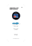
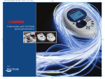
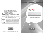
1
Outdoor Condenser: 1.5-5 Tons Cooling Only & Heat Pump
13 SEER Horizontal Discharge
User’s Manual and Installation Instructions
These units have been designed and tested for capacity and efficiency in accordance with ARI Standards for use with a
wide variety of fossil fuel furnaces, electric furnaces, air handlers, and evaporator coil combinations.
These instructions are primarily intended to assist qualified individuals experienced in the proper installation of
heating and/or air conditioning appliances. Some local codes require licensed installation/service personnel for
this type of equipment. Read all instructions carefully before starting the installation.
1
Contents
1. General Information...………………………………………………………………………………………………
2. Safety Considerations ..……………………………………………………………………………………………
3. Site Preparation ….…………………………………………………………………………………………………
4. Install the Outdoor Unit ……………………………………………………………………………………………
5. Install the Indoor Unit…...………………………………………………………………………………………….
6. Connecting Refrigerant Tubing………………………………………………………………………………….
7. Making Electric Connection.………………………………………………………………………………………
8. Start-up and Check-up…………………………………………………………………………………………….
9. Refrigerant Charging and Adjustment………………………………………………………………………….
10. Air Release………………………………………………………………………………………………………….
11. Wiring Diagrams………..………………………………………………………………………………………….
12. Outline Dimensions of Units…………………………………………………………………………………….
1. GENERAL INFORMATION
Read the following instructions completely before
performing the installation.
Condensing Unit Section — Each condensing unit
is shipped with a refrigerant charge adequate to
operate the outdoor section with an indoor matching
coil or air handler and 15 feet of refrigeration line.
NOTE: DO NOT USE ANY PORTION OF THE
CHARGE FOR PURGING OR LEAK TESTING.
Matching coils and air handlers are shipped with a
small holding charge to pressurize them to keep out
contaminants. To release the pressure, read the
indoor section of the installation instructions
carefully.
Liquid and Suction Lines — Refrigerant grade
copper tubing should be used when installing the
system. Refrigerant suction line tubing should be
fully insulated.
Field Connections for Electrical Power Supply
— All wiring must comply with the current
provisions of the “National Electrical Code” (ANSI
C1.) and with applicable local codes having
jurisdiction. Size of electrical conductors and circuit
protection must be in compliance with the
information listed on the outdoor unit data label.
2. SAFETY CONSIDERATIONS
Pressures Within the System — Split System Air
Conditioning equipment contains liquid and
gaseous refrigerant under pressure. Installation
and servicing of this equipment should be
accomplished by qualified, trained personnel
thoroughly familiar with this type of equipment.
2
2
2
3
3
3
4
4
5
6
7
8
Under no circumstances should the homeowner
attempt to install and/or service the equipment
without proper supervision from trained and
qualified service personnel.
Labels, Tags, Precautions — When working with
this equipment, follow all precautions in literature,
on tags, and on labels provided with the equipment.
Read and thoroughly understand the instructions
provided with the equipment prior to performing the
installation and operational checkout of the
equipment.
3. SITE PREPARATION
Unpacking Equipment — Remove the cardboard
carton and Installation Instruction from the
equipment.
Inspect for Damage — Inspect the equipment for
damage prior to installing the equipment at the job
site. Ensure coil fins are straight and, if necessary,
comb fins to remove flattened and bent fins.
Preferred Location of the Outdoor Unit at
the Job Site — Conduct a survey of the job
site to determine the optimum location for
mounting the outdoor unit.
Overhead
obstructions, poorly ventilated areas, and
areas subject to accumulation of debris
should be avoided. The outdoor unit should
be installed no closer than 18 inches from
the outside walls of the facility and in an
area free from overhead obstructions to
ensure unrestricted airflow through the
outdoor unit.
Facility Prerequisites — Electrical power supplied
must be adequate for proper operation of the
equipment.
The system must be wired and
provided with circuit protection in accordance with
2
local building codes and the National Electrical
Code.
through suitably waterproofed openings to prevent
water leaking into the structure.
Minimum Circuit Amperage — Electrical wiring to
the equipment must be compatible and in
compliance with the minimum circuit amperage
listed on the outdoor unit data label.
Mounting Clearance
Maximum Fuse/Circuit Breaker Size — Circuit
protection for the outdoor unit must be compatible
with the maximum fuse/circuit breaker size listed on
the outdoor unit data label.
4. INSTALLING THE OUTDOOR UNIT
Choice of Outdoor Unit Mounting Positions:
1. Don’t install unit near flammable gases or
high temperature device.
2. Don’t install unit in areas with corrosive
atmosphere.
3. Don’t install unit near the pavement or in a
position where children have access.
4. Leave spaces beside the unit as indicated
for good ventilation.
5. Install at area where installation and
maintenance is convenient.
6. In order to reduce noise and vibration, unit
should be installed firmly.
7. The maximum length of piping is 65.62 ft.
Over 22.97 ft. distance 20gm refrigerant per
is has to be added.
All our compressors are tropicalised to ensure
efficiency at high temperatures. Even so, we
recommend where temperatures exceed 104
degree F that the condensing unit is shielded
from direct sunlight.
Slab Mount — The site selected for a slab mount
installation requires a stable foundation and one not
subject to erosion. The slab should be level and
anchored (if necessary) prior to placing the
equipment on the slab.
Cantilever Mount — The cantilever mount should
be designed with adequate safety factor to support
the weight of the equipment, and for loads the
mount is subjected to during operation. Installed
equipment should be adequately secured to the
cantilever mount and leveled prior to operation of
the equipment.
Roof Mount — The method of mounting should be
designed so as not to overload roof structures nor
transmit noise to the interior of the structure.
Refrigerant and electrical lines should be routed
5. INSTALLING THE INDOOR UNIT
The indoor section of the unit should be installed
before proceeding with the routing of refrigerant
piping. Consult the Installation Instructions of the
indoor unit (i.e., air handler, fan coil unit, etc.) for
details regarding installation.
6. CONNECTING REFRIGERANT TUBING
BETWEEN INDOOR AND OUTDOOR UNITS
General Information — Once the outdoor and
indoor unit placement has been determined, route
the refrigerant tubing between the equipment in
accordance with sound installation practices.
Refrigerant tubing should be routed in a manner
that minimizes the length of tubing and the number
of bends in the tubing. Refrigerant tubing should be
supported in a manner that the tubing will not
vibrate or abrade during system operation. Tubing
should be kept clean of foreign debris during
installation and installation of a liquid line filter drier
is recommended if cleanliness or adequacy of
system evacuation is unknown or compromised.
Every effort should be made by the installer to
ensure that the field installed refrigerant containing
components of the system have been installed in
accordance with these instructions and sound
installation practices so as to insure reliable system
operation and longevity.
The maximum
recommended interconnecting refrigerant line
length is 75 feet, and the vertical elevation
difference between the indoor and outdoor sections
should not exceed 20 feet.
3
Sweat Refrigerant Pipe Fittings:
Recommended
Model
Pipe Size
CCAGSuction
Liquid
5/8″
5/8″
5/8″
5/8″
3/4″
3/4″
18
24
30
36
48
60
the
Refrigerant
Pre-Charge
[OZs]
3/8″
3/8″
3/8″
3/8″
1/2″
1/2″
5
5.94
8.58
9.9
12.1
13.2
Interconnecting Pipe Size Variations:
MODEL
CCAG
18
24
30
36
48
60
15 ft.
Liq
Gas
RECOMMENDED
30 ft.
50 ft.
Liq
Gas
Liq
Gas
65 ft.
Liq
Gas
∅3/8
∅3/8
∅3/8
∅3/8
∅1/2
∅1/2
∅3/8
∅3/8
∅3/8
∅3/8
∅1/2
∅1/2
∅3/8
∅3/8
∅3/8
∅3/8
∅1/2
∅1/2
∅5/8
∅5/8
∅5/8
∅5/8
∅3/4
∅3/4
∅5/8
∅5/8
∅5/8
∅5/8
∅7/8
∅7/8
∅3/8
∅3/8
∅3/8
∅3/8
∅1/2
∅1/2
∅7/8
∅7/8
∅7/8
∅7/8
∅1
∅1
∅7/8
∅7/8
∅7/8
∅7/8
∅1 1/8
∅1 1/8
7. MAKING ELECTRICAL CONNECTIONS
Wiring
Diagram/Schematic
—
A
wiring
diagram/schematic is located on the inside cover of
the electrical box of the outdoor unit. The installer
should
become
familiar
with
the
wiring
diagram/schematic before making any electrical
connections to the outdoor unit.
Outdoor Unit Connections — The outdoor unit
requires both power and control circuit electrical
connections.
Refer to the unit wiring
diagram/schematic for identification and location of
outdoor unit field wiring interfaces.
instructions
supplied
with
the
indoor
equipment.
Electrical Wiring — Electrical wiring must
comply with the current provisions of the
“National Electrical Code” (ANSI C1.) and
with
applicable
local
codes
having
jurisdiction. Use of rain tight conduit is
recommended. Electrical conductors shall
have
minimum
circuit
amperage
in
compliance with the outdoor unit rating
label. The facility shall employ electrical
circuit protection at a current rating no
greater than that indicated on the outdoor
unit rating label.
Electric Data
MODEL
CCAG-
Power
V/Ph/HZ
18
24
30
36
48
60
208230/1/60
Compressor
Fan
MCA
RLA
LRA
FLA
AMP.
10
11.4
41
56
0.48
1.56
13.6
16.4
20.4
21.4
67
83
109
137
1.56
.72x2
.72x2
1.56x2
RLA-Rated Load Amp.
LRA-Locked Rotor Amp.
MCA-Minimum Circuit Amp per section NEC 430-24
15
20
20
25
30
35
FLA-Full Load Amp.
Disconnect Switch — An electrically compatible
disconnect switch must be within line of sight of the
outdoor unit. This switch shall be capable of
electrically de-energizing the outdoor unit.
Optional Equipment — Optional equipment
requiring connection to the power or control circuits
shall be wired in strict accordance with current
provisions of the “National Electrical Code” (ANSI
C1.), with applicable local codes having jurisdiction,
and the Installation Instructions provided with the
equipment. Optional Equipment (i.e., liquid line
solenoid valves, hard start kits, low suction
pressure cutout switch kit, high pressure cutout
switch kit, refrigerant compressor crankcase heater,
etc.) should be installed in strict accordance with
the manufacturer’s Installation Instructions.
8. START-UP AND CHECKOUT
Control Circuit Wiring — The outdoor unit is
designed to operate from a 24 VAC control circuit.
Control circuit wiring must comply with the current
provisions of the “National Electrical Code” (ANSI
C1.) and with applicable local codes having
jurisdiction.
Thermostat
Connections
—
Thermostat
connections should be made in accordance with the
instructions supplied with the thermostat and with
Air Filters — Ensure air filters are clean and in
place prior to operating the equipment.
Thermostat — Set the room thermostat function
switch to OFF, fan switch to AUTO, and move the
temperature set-point to it’s highest setting.
Prior to applying electrical power to the outdoor
unit, ensure that the unit has been properly and
securely grounded.
Prior to applying electricity to the outdoor unit,
4
ensure power supply connections have been made
at the facility power interface and at the outdoor
unit.
Outdoor Unit — Ensure the outdoor coil and front
of the unit are free from obstructions and debris,
and all equipment access/control panels are in
place.
Functional Checkout:
Indoor Blower — Set the thermostat function
switch to “Cooling” and the fan switch to ON or
MAN. Verify that the Indoor Blower is operating
and that airflow is not restricted. Set the fan switch
back to Auto.
Cooling — Gradually lower the thermostat
temperature set point below the actual room
temperature and observe that the outdoor unit and
indoor blower energize.
Feel the air being
circulated by the indoor blower and verify that it is
cooler than ambient temperature. Listen for any
unusual noises. If present, locate and determine
the source of the noise and correct as necessary.
Heating — If provided with heating equipment,
lower the thermostat temperature to the lowest
obtainable setting and set the thermostat function
switch to “Heating." The indoor blower and outdoor
unit should stop running. Increase the set-point
temperature of the thermostat to the maximum
setting. Verify that the heating equipment has been
energized (i.e., fossil fuel burner operating, etc.)
and that the indoor blower energizes after a short
period of time. Feel the air being circulated by the
indoor blower and verify that it is warmer than
ambient temperature.
Listen for any unusual
noises. If present, locate and determine the source
of the noise and correct as necessary.
9. REFRIGERANT CHARGING AND
ADJUSTMENT
procedures supplied with the equipment.
Note: Do not vent or depressurize unit refrigerant to
atmosphere. Remove and recover refrigerant
following practice.
Two methods to check or adjust refrigerant charge:
A: Super Heat Method (Cooling, Non-TXV)
1. Operate system at cooling for at least 15
minutes.
2. Measure refrigerant pressure Psc at suction valve
service port.
3. Measure suction line temperature Tsc1 by attaching
and insulating thermometer probe to suction line
close to the service valve.
4. Measure air dry bulb temperature Tod at outdoor
condenser inlet.
5. Measure air web bulb temperature Tiw at indoor
evaporator inlet.
6. By using Tod and Tiw in Table A, intersect to get
superheat temperature Tsp.
7. By using Tsp and Psc in Table B, intersect to get
suction line temperature Tsc2 temperature Tsp.
8. If Tsc1 is higher than Tsc2, add refrigerant and
repeat above steps till Tsc1=Tsc2.
9. If Tsc1 is lower than Tsc2, remove refrigerant and
repeat above steps till Tsc1=Tsc2.
B: Subcooling Method (Cooling, TXV)
1. Operate system at cooling for at least 15
minutes.
2. Measure refrigerant pressure Psc at suction valve
service port.
3. Measure suction line temperature Tsc1 by attaching
and insulating thermometer probe to suction line
close to the service valve.
4. In Table C, by intersecting required subcooling
temperature Tsb and measured refrigerant pressure
Psc, get required suction line temperature Tsc2.
5. If Tsc1 is lower than Tsc2, remove refrigerant;
otherwise, add refrigerant.
NOTE: The Refrigerant Charging Charts are applicable
to matched assemblies of our equipment and at listed
airflow for the indoor coil. Assemblies of indoor coils
and outdoor units not listed are not recommended and
deviations from rated airflow or non-listed equipment
combinations may require modifications to the expansion
device(s) and refrigerant charging procedures for proper
and efficient system operation.
Refrigerant Charging Chart — Refer to Refrigerant
Charging Charts for correct system charging and to
Orifice Usage Chart for correct restrictor sizes.
Optional Equipment — A functional checkout should
be performed in specific accordance with the checkout
5
Table A-Superheat Tsp (F)
Outdoor
Temp. Tod(F)
55
60
65
70
75
80
85
90
95
100
105
110
115
Indoor Coil EnteringAir Wet Bulb(F)-Tiw
50 52 54 56 58 60 62 64 66 68 70 72 74 76
9 12 14 17 20 23 26 29 32 35 37 40 42 45
7 10 12 15 18 21 24 27 30 33 35 38 40 43
/ 6 10 13 16 19 21 24 27 30 33 36 38 41
/ / 7 10 13 16 19 21 24 27 30 33 35 39
/ / / / 9 12 15 18 21 24 26 31 34 37
/ / / / 5 8 12 15 18 21 25 28 31 35
/ / / / / / 8 11 15 19 22 26 30 33
/ / / / / / 5 9 13 16 20 24 27 31
/ / / / / / / 6 10 14 18 22 25 29
/ / / / / / / / 8 12 15 20 23 27
/ / / / / / / / 5 9 13 17 22 26
/ / / / / / / / / / 11 15 20 25
/ / / / / / / / / / 8 14 18 23
10. AIR RELEASE
Purge the air within the indoor unit and piping
from the system by using a vacuum pump.
1. Release air as the diagram above shows.
2. Shows the vacuum pump operating 15 minutes
at least. Read gauge meter and make sure
pressure reaches-29.92 in Hg.
3. After ± the vacuum pump is turned off. Please
wait a few minutes and check the gauge meter
doesn’t change reading to confirm no leakage in
the piping.
4. Shows locked position.
5. Please test for leaks with gas detection
instrument or soapy water before turning on the
system (unit).
Table B-Suction Line Temperature Tsc2 (F)
Superheat
Temp. Tsp(F)
0
2
4
6
8
10
12
14
16
18
20
22
24
26
28
30
32
34
36
38
40
Suction Pressue at Service Port Psc (PSIG)
61.5 64.2 67.1 70.0 73.0 76.0 79.2 82.4 85.7
35 36 39 41 43 45 47 49 51
37 39 41 43 45 47 49 51 53
39 41 43 45 47 49 51 53 55
41 43 45 47 49 51 53 55 57
43 45 47 49 51 53 55 57 59
45 47 49 51 53 55 57 59 61
47 49 51 53 55 57 59 61 63
49 51 53 55 57 59 61 63 65
51 53 55 57 59 61 63 65 67
53 55 57 59 61 63 65 67 69
55 57 59 61 63 65 67 69 71
57 59 61 63 65 67 69 71 73
59 61 63 65 67 69 71 73 75
61 63 65 67 69 71 73 75 77
63 65 67 69 71 73 75 77 79
65 67 69 71 73 75 77 79 81
67 69 71 73 75 77 79 81 83
69 71 73 75 77 79 81 83 85
71 73 75 77 79 81 83 85 87
73 75 77 79 81 83 85 87 89
75 77 79 81 83 85 87 89 91
Table C: Suction Tube Temperature Tsc2
L iq u id P r e s s u e a t S e r v ic e V a lv e P s c ( P S I G )
R e q u ir e d S u b c o o li n g T s b ( F ) 1 3 4
141
148
156
163
171
179
187
195
205
214
223
233
243
253
264
274
285
297
309
321
331
346
359
0
76
79
82
85
88
91
94
97
100
103
106
109
112
115
118
121
124
127
130
133
136
139
142
145
5
71
74
77
80
83
86
89
92
95
98
101
104
107
110
113
116
119
122
125
128
131
134
137
140
10
66
69
72
75
78
81
84
87
90
93
96
99
102
105
106
111
117
120
123
126
129
129
132
135
15
61
64
67
70
73
75
79
82
85
88
91
94
97
100
103
106
109
112
115
118
121
124
127
130
20
56
59
62
65
68
71
74
77
80
83
86
89
92
95
98
101
104
107
110
113
116
119
122
125
25
51
54
57
60
63
66
69
72
75
78
81
84
87
90
93
96
99
102
105
108
111
114
117
120
6
11. WIRING DIAGRAMS
CCAG-18-CFN, CCAG-24-CFN, CCAG-30-CFN
CCAG-36 –CFN, CCAG-48 –CFN, CCAG-60 –CFN
7
12. OUTLINE DIMENSIONS OF UNITS
Model
CCAG-18-CFN
CCAG-24-CFN
CCAG-30-CFN
CCAG-36-CFN
CCAG-48-CFN
CCAG-56-CFN
A
31.3
31.3
37.4
47.3
47.3
48.3
Unit Outside Dimensions
B
C
D
37.4 12.6
3.8
37.4 15.4
3.8
37.4 15.4
3.8
37.4 15.4
3.8
37.4 15.4
3.8
37.4 15.4
3.8
E
6.2
6.2
6.2
6.2
6.2
6.2
Valve Size(Inch)
Liq.
Gas
3/8
5/8
3/8
5/8
3/8
5/8
3/8
5/8
1/2
3/4
1/2
3/4
8
ESPITECH, 680H Industrial Ct., Chesterfield, MO 63005
Tel: (636) 536-9446 Fax: (636) 536-9441
Email: [email protected] Web Site: www.espitechllc.com
SE0030106
9