1
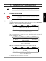
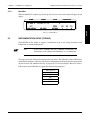
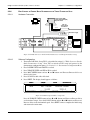
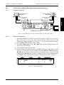
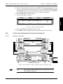
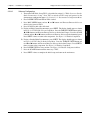
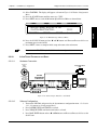
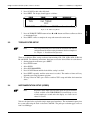
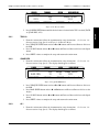
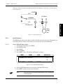
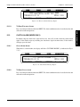
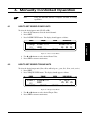
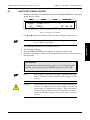
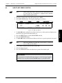
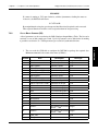
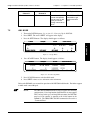
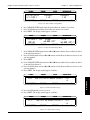
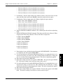
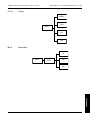
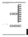
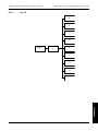
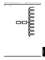
Chapter 8 – Optional Equipment Magtrol Model DSP7000 Dynamometer Controller 15. Press SCALE I button to select yes or no. 16. Press SHIFT. The display should appear as follows: POWER IO X TORQUE SPEED USER DISPLAY USE DACS AS TORQUE & SPEED? XXX BRAKE STATUS SET POINT SET POINT P I D Figure 8–8 Torque/Speed Setup 17. Press SCALE I button to select yes. 18. Press SHIFT. The display should appear as follows: POWER IO CARDX TORQUE SPEED USER DISPLAY TORQUE DAC SPEED DAC 0.000 UNITS/V 0.000 RPM/V BRAKE STATUS SET POINT SET POINT P I D Figure 8–9 Torque/Speed DAC Setup Menu 19. Press TORQUE UNITS button and use and buttons and the Decrease/Increase dial to set the desired Torque DAC vlaue. 20. Press MAX SPEED button and use and buttons and the Decrease/Increase dial to set the desired Speed DAC value. 21. Press SHIFT 2 times to complete configuration and return to the main menu. 8.1.3.1 Torque DAC Scale Factor Torque DAC Scale Factor is scaled in displayed torque units/volt. Example: If the displayed torque units are set to oz·in. and the Torque DAC scale is set to 1 unit/volt, then 1 oz·in. will result in 1 volt at the torque output. Speed DAC Scale Factor Speed DAC Scale Factor is scaled in rpm/volt. Example: If the Speed DAC scale is set to 1000 rpm/volt, then 1000 rpm will result in 1 volt at the speed output. 8.1.3.3 I/O Card A/D Input Signal Range The input signals of the I/O card are from -10V to +10V. 8.1.3.4 I/O Card DAC Output Signal Range The output singals of the DAC is from -10V to +10V. 90 operation 8.1.3.2