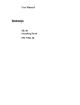
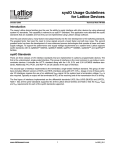
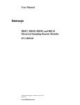
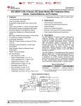
1
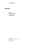
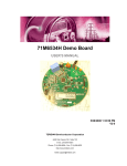
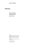
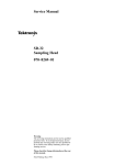
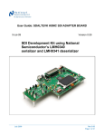
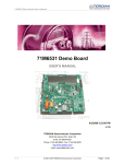
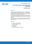
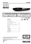
LVDS Evaluation Kits
Chapter 7
7.0.0 LVDS EVALUATION BOARDS AND EVALUATION KITS
Evaluation kits, offered at a nominal cost, demonstrate the LVDS Physical Layer Interface devices. Please
consult the LVDS website for a link to the page that provides updated information on the Evaluation Kits.
The “Evaluation/Demo Board” page contains:
• LVDS Family (LVDS, Channel Link, Bus LVDS, etc)
• A short description of the board or kit
• A list of the NSID(s) (part numbers) that are on the PCBs
• The kit’s order number (Order Number)
• An update/revision/errata link (if applicable)
Also note that on selected kits, the user’s manual for the specific kit can now be downloaded directly
from this page. This allows the user to determine exactly the content, capability, and features of the kit
prior to purchasing the kit.
7.1.0 LVDS KITS - SHORT DESCRIPTIONS
7.1.1 The Generic LVDS Evaluation Boards
The Generic LVDS Evaluation Board is used to measure LVDS signaling performance over different media.
Individual LVDS channels can be evaluated over PCB trace, twisted pair cable, or custom transmission
medium. Flow through LVDS quad drivers and receivers are used on the board. They can represent the
LVDS I/O characteristics of most of National’s 3.3V LVDS devices. Included in the latter part of this section
is the complete user’s documentation for the new LVDS47/48EVK. See Section 7.2.0 below.
While supplies last, the original generic LVDS evaluation board is available as both an assembled kit
(LVDSEVAL-001) and also as an un-stuffed PCB (order as a literature piece, LIT# 550061-001). This PCB
accommodates a SCSI-2 50 pin cable interface.
7.1.2 Channel Link Evaluation Kits
These boards are fully populated. TTL signals are accessed through IDC connectors on the transmitter
and receiver boards. The boards are interconnected via a ribbon cable that can be modified for custom
lengths for the 21 & 28-bit chipsets. The 48-bit chipset features a 3M MDR cable and connector system.
These evaluation boards are useful for analyzing the operation of National’s high-speed Channel Link
devices.
7.1.3 Bus LVDS Evaluation Kits
These boards are fully populated. Currently a mini backplane kit is offered (different RX device options
available). A stand-alone test system is also offered. The BLVDS03 kit provides a PRBS generator that
provides data to the BLVDS Serializer and also checks the received data from the BLVDS Deserializer. This
kit only requires a power supply voltage. These evaluation boards are useful for analyzing the operation
of National’s New Bus LVDS SER/DES devices.
www.national.com/appinfo/lvds/
LVDS Owner’s Manual
73
7.1.4 Special Function LVDS Evaluation Kits
New special function LVDS/BLVDS devices are being developed for special applications. The first EVAL
KIT is for the DS90CP22 2x2 800Mbps Digital Crosspoint Switch. Check our website for the latest information on new kits.
7.1.5 FPD-Link Evaluation Kits
These boards are fully populated. TTL signals are accessed through IDC connectors on the transmitter
and receiver boards. The boards are interconnected via a cable. These evaluation boards are useful for
analyzing the operation of National’s high-speed FPD-Link and LDI devices. Current information on the
FPD Link Evaluation Kits can be accessed from the FPD website at: www.national.com/appinfo/fpd/
7.1.5 Related Parts
• Use the DS90C031/032 on the original generic LVDS evaluation board (LVDSEVAL-001) to represent
the LVDS I/O characteristics of all 5V drivers/receivers, 5V Channel Link, and 5V FPD-Link devices.
• Use the DS90LV047A/048A on the new generic LVDS evaluation board (LVDS47/48EVK) to represent
the LVDS I/O characteristics of 3V Channel Link, 3V FPD-Link, and other 3V devices.
The remainder of this chapter explains the operation of the new generic LVDS Evaluation Board.
7.2.0 THE GENERIC LVDS EVALUATION KIT – THE LVDS4748EVK
7.2.1 The Flow Through LVDS Evaluation Board
The Flow Through LVDS Evaluation Board
The Flow Through LVDS Evaluation Board is used to measure LVDS signaling performance over different
media. Individual LVDS channels can be evaluated over a PCB trace, RJ45 connector and CAT5 UTP
cable, or custom transmission medium. Though LVDS quad drivers and receivers are used on the board,
they can represent the standard LVDS I/O characteristics of most of National’s LVDS devices. We can
also use the DS90LV047A/048A to represent the LVDS I/O characteristics of 3V Channel Link and 3V
FPD-Link devices.
74
www.national.com/appinfo/lvds/
7.2.2 Purpose
The purpose of the Low Voltage Differential Signaling (LVDS) Evaluation Printed Circuit Board (PCB) is to
demonstrate the line driving capability of LVDS technology across a short PCB interconnect, and also
across a variable length of RJ45 cable. Probe points for a separate driver and a separate receiver are
also provided for individual line driver or receiver testing. The part number for the Evaluation Kit is
LVDS47/48EVK. In this application note, the following differential signal nomenclature has been used:
“Jx-3” represents the true signal and “Jx-1” represents the inverting signal. On the PCB, the true signal
is represented by a ‘+’ and the inverting signal is on the adjacent header pin as shown below.
Double Row
GND 4
Header
+
3
2 GND
+
3
4 GND
–
–
–
1
2 GND
GND 2
1
J5
J6
1
3
+
4 GND
J7, J8
The two adjacent ground pins are there to view the true or inverting signal single-endedly. Input signals
are represented with an “I” while receiver outputs are represented with an “O.”
7.2.3 Five Test Cases
Five different test cases are provided on this simple 4 layer FR-4 PCB. Each case is described separately.
The five test cases are shown in the following figure.
LVDS Channel #1A: LVDS Line Driver
This test channel provides test points for an isolated driver with a standard 100Ω differential termination
load. Probe access for the driver outputs is provided at test points on J5-1 and J5-3. The driver input signal (I1) is terminated with a 50Ω termination resistor (RT1) on the bottom side of the PCB.
LVDS Channel #1B: LVDS Receiver
This test channel provides test points for an isolated receiver. Termination options on the receiver inputs
accommodate either two separate 50Ω terminations (RT5 and RT6) (each line to ground) or a 100Ω resistor connected across the inputs (differential). The first option allows for a standard signal generator
interface. Input signals are connected at test points I5 (RIN-) and I6 (RIN+). A PCB option for a series 453Ω
resistor (RS1) is also provided in case 50Ω probes are employed on the receiver output signal. The
default setting is with two separate 50Ω terminations (RT5 and RT6) and without the series 453Ω resistor
(RS1) for use of high impedance probes. The receiver output signal may be probed at test point O1.
LVDS Channel #2: PCB Interconnect
This test channel connects Driver #2 to Receiver #2 via a pure PCB interconnect. A test point interface of
the LVDS signaling is provided at test point J6-1 and J6-3. The driver input signal (I2) is terminated with a
50Ω termination resistor (RT2) on the bottom side of the PCB. The receiver output signal may be probed
at test point O2. A PCB option for a series 453Ω resistor (RS2) is also provided in case 50Ω probes are
employed on the receiver output signal. The default setting is without the series 453Ω resistor for use of
high impedance probes. A direct probe connection is possible with a TEK P6247 differential probe high
impedance probe (>1GHz bandwidth) on the LVDS signals at test points J6-1 and J6-3. This channel may
be used for analyzing the LVDS signal without the bandwidth limiting effects of a cable interconnect.
LVDS Channel #3: Cable Interconnect
This test channel connects Driver #3 to Receiver #3 via the cable interconnect. A test point interface is
provided at the receiver input side of the cable. The driver input signal (I3) is terminated with a 50Ω termination resistor (RT3) on the bottom side of the PCB. LVDS signals are probed via test points on J7.
The receiver output signal may be probed at test point O3. A PCB option for a series 453Ω resistor (RS3)
is also provided in case 50Ω probes are employed on the receiver output signal (see options section).
The default setting is without the series 453Ω resistor for use of high impedance probes. A differential
probe connection is possible with a TEK P6247 differential probe (>1GHz bandwidth) on the LVDS signals
at test point J7-1 and J7-3.
www.national.com/appinfo/lvds/
LVDS Owner’s Manual
75
LVDS Channel #4: Cable Interconnect
This test channel connects Driver #4 to Receiver #4 also via the cable interconnect. A test point interface
is provided at the receiver input side of the cable. The driver input signal (I4) is terminated with a 50Ω
termination resistor (RT4) on the bottom side of the PCB. LVDS signals are probed via test points on J8.
The receiver output signal may be probed at test point O4. A PCB option for a series 453Ω resistor (RS4)
is also provided in case 50Ω probes are employed on the receiver output signal. The default setting is
without the series 453Ω resistor for use of high impedance probes. A differential probe connection is
possible with a TEK P6247 differential probe (>1 GHz bandwidth) on the LVDS signals at test point J8-1
and J8-3. This channel duplicates channel #3 so that it may be used for a clock function or for cable
crosstalk measurements.
J3
VCC
GND
EN
I1
J5-3
100Ω
RL2
Driver
50Ω
RT1
Channel #1A
J5-1
J4
50Ω
RT5
VCC
GND
EN
I5
RS1
453Ω
+
100Ω
Receiver
RT5/RT6
I6
Channel #1B
-
O1
50Ω
RT6
J3
VCC
GND
VCC
J4
GND
EN
EN
Channel #2
I2
J6-3
100Ω
RL1
Driver
50Ω
RT2
PCB trace
VCC
GND
Driver
50Ω
RT3/RT4
J6-1
Receiver
-
O2
Channel #3 and #4
J3
J2
J1
EN
I3/I4
RS2
453Ω
+
C
o
n
n
e
c
t
o
r
Cable
C J7-3/J8-3
o
n
100Ω
n
RL3/RL4
e
c
t
o J7-1/J8-1
r
J4
VCC
GND
EN
+
RS3/RS4
453Ω
Receiver
-
O3/04
PCB Block Diagram
76
www.national.com/appinfo/lvds/
7.2.4 Interconnecting Cable and Connector
The evaluation PCB has been designed to directly accommodate a CAT 5 four twisted pair (8-pin) RJ45
cable. The pinout, connector, and cable electrical/mechanical characteristics are defined in the Ethernet
standard and the cable is widely available. The connector is 8 position, with 0.10” centers and the pairs
are pinned out up and down. For example, pair 1 is on pins 1 and 5, not pins 1 and 2 (see Figure below).
IMPORTANT NOTE: The 2 unused pairs are connected to ground. Other cables may also be used if they
are built up.
1 2 3 4
5 6 7 8
cable
RJ45 Connector
7.2.5 PCB Design
Due to the high-speed switching rates obtainable by LVDS, a minimum of a four layer PCB construction
and FR-4 material is recommended. This allows for 2 signal layers and full power and ground planes.
The stack is: signal (LVDS), ground, power, signal.
Differential traces are highly recommended for the driver outputs and the receiver inputs signal (LVDS
signals, refer to PCB layout between U1 and J1). Employing differential traces will ensure a low emission design and maximum common-mode rejection of any coupled noise. Differential traces require that
the spacing between the differential pair be controlled. This distance should be held as small as possible
to ensure that any noise coupled onto the lines will primarily be common-mode. Also, by keeping the
pair close together the maximum canceling of fields is obtained. Differential impedance of the trace pair
should be matched to the selected interconnect media
W S W
(cable’s differential characteristic impedance). Equations for
t
calculating differential impedance are contained in National
application note AN-905 for both microstrip and stripline differential PCB traces.
h
r
3
For the microstrip line, the differential impedance, ZDIFF, is:
ZDIFF 2ZO (1 – 0.48e-0.96S/h)Ω
For the new evaluation board h = 24mils, S = 11mils
and ZO = 70Ω. Calculating the differential impedance, ZDIFF, is:
ZDIFF 2ZO (1 – 0.48e-0.96(11/24))Ω
2 (70) (0.69086)Ω
96.72Ω
Termination of LVDS lines is required to complete the current loop and for the drivers to properly operate. This termination in its simplest form is a single surface mount resistor (surface mount resistor mini-
www.national.com/appinfo/lvds/
LVDS Owner’s Manual
77
mizes parasitic elements) connected across the differential pair as close to the receiver inputs as possible
(should be within 0.5 inch (13mm) of input pins). Its value should be selected to match the interconnects
differential characteristics impedance. The closer the match, the higher the signal fidelity and the less
common-mode reflections will occur (lower emissions too). A typical value is 100Ω ±1%.
LVDS signals should be kept away from CMOS logic signals to minimize noise coupling from the large
swing CMOS signals. This has been accomplished on the PCB by routing CMOS signals on a different
signal layer (bottom) than the LVDS signals (top) wherever possible. If they are required on the same
layer, a CMOS signal should never be routed within three times (3S) the distance between the differential
pair (S). Adjacent differential pairs should be at least 2S away also.
W
A
B
Pair 1
>2S
A
S
>3S
B
Pair 2
TTL/CMOS
Pair Spacing for Differential Lines
Bypassing capacitors are recommended for each package. A 0.1 µF is sufficient on the quad driver or
receiver device (CB1 and CB2) however, additional smaller value capacitors may be added (i.e. 0.001µF at
CB21 and CB22) if desired. Traces connecting VCC and ground should be wide (low impedance, not 50Ω
dimensions) and employ multiple vias to reduce inductance. Bulk bypassing is provided (CBR1, close by)
at the main power connection as well. Additional power supply high frequency bypassing can be added
at CB3, CB13, and CB23 if desired.
7.2.6 Sample Waveforms from the LVDS Evaluation PCB
Single-ended signals are measured from each signal (true and inverting signals) with respect to ground.
The receiver ideally switches at the crossing point of the two signals. LVDS signals have a VOD specification of 250mV to 450mV with a typical VOS of 1.2V. Our devices have a typical VOD of 300mV, but for the
example below, we will use a signal between 1.0 V (VOL) and 1.4 V (VOH) for a 400 mV VOD. The differential waveform is constructed by subtracting the Jx-1 (inverting) signal from the Jx-3 (true) signal. VOD =
(Jx-3) – (Jx-1). The VOD magnitude is either positive or negative, so the differential swing (VSS) is twice
the VOD magnitude. Drawn single-ended waveforms and the corresponding differential waveforms are
shown in the following figure.
78
www.national.com/appinfo/lvds/
Single-Ended Waveforms
A 1.4V (VOH)
+VOD
+100mV
0V Differential (+1.2V)
-100mV
B 1.0V (VOL)
Ground
Differential Waveform
+VOD
A – B = 0V
VSS
-VOD
Single-Ended & Differential Waveforms
The PCB interconnect signal (LVDS Channel #2) can be measured at the receiver inputs (test points J6-1
and J6-3). Due to the short interconnect path via the PCB little distortion to the waveform is caused by
the interconnect. See figure below. Note that the data rate is 100Mbps and the differential waveform
(VDIFF = DOUT2+ - DOUT2-) shows fast transition times with little distortion.
In the next four figures, the top two waveforms are the single-ended outputs (between the driver and
receiver), the middle waveform is the calculated differential output signal from the two single-ended
signals and the bottom waveform is the output TTL signal from the receiver.
200mV/div
DOUT2+ J6-3
500mV/div
(DOUT2+) - (DOUT2-)
2V/div
DOUT2- J6-1
ROUT2 O2
5ns/div
LVDS Channel #2 Waveforms — PCB Interconnect
www.national.com/appinfo/lvds/
LVDS Owner’s Manual
79
The cable interconnect signal is also measured at the receiver inputs (test points J7-1 & J7-3 and J8-1 & J83). Due to the characteristics of the cable some waveform distortion has occurred. Depending upon the
cable length and quality, the transition time of the signal at the end of the cable will be slower than the
signal at the driver’s outputs. This effect can be measured by taking rise and fall measurements and
increasing the cable length. A ratio of transition time to unit interval (minimum bit width) is a common
gauge of signal quality. Depending upon the application ratios of 30% to 50% are common. These measurements tend to be more conservative than jitter measurements. The waveforms acquired with an RJ45
cable of 1 meter, 5 meters and 10 meters in length are shown in the next three figures. Note the additional
transition time slowing due to the cable’s filter effects on the 5 meter and 10 meter test case.
200mV/div
DOUT3+ J7-3
500mV/div
(DOUT3+) - (DOUT3-)
2V/div
DOUT3- J7-1
ROUT3 O3
5ns/div
LVDS Channel #3 Waveforms - 1m Cable Interconnect
80
www.national.com/appinfo/lvds/
200mV/div
DOUT3+ J7-3
500mV/div
(DOUT3+) - (DOUT3-)
2V/div
DOUT3- J7-1
ROUT3 O3
5ns/div
LVDS Channel #3 Waveforms - 5m Cable Interconnect
200mV/div
DOUT3+ J7-3
500mV/div
(DOUT3+) - (DOUT3-)
2V/div
DOUT3- J7-1
ROUT3 O3
5ns/div
LVDS Channel #3 Waveforms - 10m Cable Interconnect
www.national.com/appinfo/lvds/
LVDS Owner’s Manual
81
7.2.7 Probing of High-Speed LVDS Signals
Probe specifications for measuring LVDS signals are unique due to the low drive level of LVDS (3 mA typical). Either a high impedance probe (100kΩ or greater) or the TEK P6247 differential probe (>1GHz bandwidth) must be used. The capacitive loading of the probe should be kept in the low pF range, and the
bandwidth of the probe should be at least 1 GHz (4 GHz preferred) to accurately acquire the waveform
under measurement.
National’s Interface Applications group employs a wide range of probes and oscilloscopes. One system
that meets the requirements of LVDS particularly well is a TEK TDS 684B Digital Real Time scope (>1GHz
bandwidth) and TEK P6247 differential probe heads. These probes offer 200kΩ, 1pF loading and a bandwidth of 1GHz. This test equipment was used to acquire the waveforms shown.
500mV/div
The TEK P6247 differential probes may be used to measure the differential LVDS signal or each signal of
the differential pair single-ended. This test equipment was used to acquire the waveforms differentially
as well as single-endedly with the differential signal calculated by (DOUT+) – (DOUT-) shown in the figure
below. You can see that both of the differential signals look identical. The method in which you acquire
the single-ended signals is important (such as matching probe types and lengths) if you intend to calculate the differential signal from the two single-ended signals.
DIFF DOUT2 J6-1/3
Tek P6247 DIFF PROBE
500mV/div
(DOUT2+) - (DOUT2-)
Tek P6247 DIFF PROBE
Single-Ended w/Math
2V/div
ROUT2 O2
5ns/div
LVDS Channel #2 Waveforms - Differential and Calculated Differential from Single-Ended Waveform
LVDS waveforms may also be measured with high impedance probes such as common SD14 probe
heads. These probes offer 100kΩ, 0.4pF loading and a bandwidth of 4 GHz. These probes connect to a
TEK 11801B scope (50 GHz bandwidth). Probes with standard 50Ω loading should not be used on LVDS
lines since they will load them too heavily. 50Ω probes may be used on the receiver output signal in
conjunction with the 453Ω series resistor option (see option section below). Note that the scope waveform is an attenuated signal (50Ω/(450Ω + 50Ω) or 1/10) of the output signal and the receiver output is
loaded with 500Ω to ground.
82
www.national.com/appinfo/lvds/
7.2.8 Demo PCB Options
Option 1: 453Ω Resistors
A provision for a series 453Ω resistor (RS1, RS2, RS3 and RS4) is provided on the receiver output signal. By
cutting the trace between the “RS” pads and installing a 453Ω resistor, a standard 50Ω scope probe may be
used (500Ω total load). Note that the signal is divided down (1/10) at the scope input.
Option 2: Disabling the LVDS Driver
The quad driver features a ganged enable. An active high or an active low input are provided. On the evaluation PCB, the active low input (EN*) is routed to ground. The active high input (EN) is routed to a jumper
(J3). The jumper provides a connection to the VCC plane (“ON”) or to the Ground plane (“OFF”). To enable
the driver, connect the jumper to the power plane, to disable the driver connect the jumper to the ground.
Option 3: Disabling the LVDS Receiver
The quad receiver features a ganged enable (same as the driver). An active high or an active low are
provided. On the evaluation PCB, the active low input (EN*) is routed to ground. The active high input
(EN) is routed to a jumper (J4). The jumper provides a connection to the VCC plane (“ON”) or to the
Ground plane (“OFF”). To enable the receiver, connect the jumper to the power plane, to disable the
receiver connect the jumper to ground.
Option 4: Cables
Different cables may also be tested (different lengths, materials, constructions). A standard RJ45 8-pin
connector/pinout has been used (J1 and J2). Simply plug in the RJ45 1 meter or 5 meter cables included
in the kit or build a custom cable.
Option 5: SMA or SMB Connectors
Both SMA and SMB connectors will fit the footprint on the boards for the driver inputs I1-4, receiver outputs O1-4 and the single receiver inputs I5-6. The board is loaded with SMBs on I4 and O4.
Option 6: Receiver Termination (Channel #1B)
The separate receiver input signals can be terminated separately (50Ω on each line to ground) utilizing
pads RT5 (inverting to ground) and RT6 (true input to ground) for a signal generator interface. In addition, a single 100Ω differential resistor (across pads RT5 and RT6) can be used if the device is to be driven by a differential driver. Be sure to remove the 50Ω termination resistors RT5 and RT6 if you plan to
use the 100Ω differential resistor.
7.2.9 Plug & Play
The following simple steps should be taken to begin testing on your completed evaluation board:
1. Connect signal common (Ground) to the pierced lug terminal marked GND
2. Connect the power supply lead to the pierced lug terminal marked VCC (3.3V)
3. Set J3 & J4 jumpers to the power plane (“ON”) to enable the drivers and receivers
4. Connect enclosed RJ45 cable between connectors J1 and J2
5. Connect a signal generator to the driver input (I4) with:
a) frequency = 50 MHz (100 Mbps)
b) VIL = 0V & VIH = 3.0V
c) tr & tf = 2 ns
d) duty cycle = 50% (square wave)
6. Connect differential probes to test points J8-1 and J8-3
7. View LVDS signals using the same voltage offset and volts/div settings on the scope with the TEK
P6247 differential probes. View the output signal on a separate channel from test point O4. The
signals that you will see should resemble the LVDS Channel #3 Waveform - 1m or 5m Cable
Interconnect figure.
www.national.com/appinfo/lvds/
LVDS Owner’s Manual
83
7.2.10 Common-Mode Noise
When the receiver (DS90LV048A) is enabled, a small amount of common-mode noise is passed from the
output of the receiver to the inputs as shown in the next figure. This noise shows up on the singleended waveforms, but does not impact the differential waveform that carries the data. A design
improvement was made to the DS90LV048A to reduce the magnitude of the noise coupled back to the
inputs, reducing the feedback by 30% compared to prior devices. This noise will not be observed if the
receiver device is disabled by setting J4 to “OFF” as shown in the following figure.
200mV/div
RIN1+ I6
RIN1- I5
2V/div
ROUT1 O1
5ns/div
LVDS Channel #1B Waveforms
A Small Amount of Common-Mode Noise Coupled from Output to Input
84
www.national.com/appinfo/lvds/
200mV/div
RIN1+ I6
RIN1- I5
5ns/div
LVDS Channel #1B Waveforms – Output Disabled
7.2.11 Summary
This evaluation PCB provides a simple tool to evaluate LVDS signaling across different media and
lengths to determine signal quality for high-speed data transmission applications.
7.2.12 Appendix
Typical test equipment used for LVDS measurements:
Signal Generator TEK HFS 9009
Oscilloscope
TEK TDS 684B Digital Real Time scope, TEK 11801B scope
Probes
TEK P6247 differential probe, TEK SD-14 probe
LVDS Owner’s Manual
85
Bill of Materials
Type
IC
Label
U1
Value/Tolerance
(Quad Driver)
IC
U2
(Quad Receiver)
1
Connector
J1, J2
(8-pin RJ45)
2
Resistor
RT1-6
50Ω
6
RC0805
Resistor
RL1-4
100Ω
4
RC0805
Resistor
RS1, RS2, RS3, RS4
453Ω
Capacitor
CB1, CB2, CB3
0.1µF
3
CC0805
Capacitor
CB13
0.01µF
1
CC0805
Capacitor
CB21, CB22, CB23
0.001µF
3
CC0805
Capacitor
Headers
Headers
CBR1
J3, J4
J5, J6, J7, J8
10µF, 35V
3 lead header
4 lead header
1
D
Solid Tantalum Chip Capacitor
100 mil spacing (single row header)
100 mil spacing (double row header)
0.1 jumper post shunts
2
SMB Connector
Johnson P/N 131-3701-201
0/8 SMB Connector
SMA Connector
Johnson P/N 131-3701-201
Johnson P/N 142-0701-201
Jumpers
SMB Jack
I4, O4
*SMB Jack or
*SMA Jack
I1-3, I5-6, O1-3
Plug (banana)
VCC, GND
Cable
Qty Footprint
1 16-L TSSOP
16-L TSSOP
DS90LV048ATMTC
AMP P/N 558310-1
0/4 RC0805
2
4
2
Part Number
DS90LV047ATMTC
not loaded
Uninsulated Standard
Pierced Lug Terminal
2
Johnson P/N 108-0740-001
RJ45 Cable
2
1 meter and 5 meter
Legs
4
Bolts/washers
4
PCB
1
LVDS47/48PCB
* Note: On the evaluation board, inputs I1-3, I5-6 and outputs O1-3 are not loaded with connectors.
These inputs and outputs can be loaded with either SMBs (P/N 131-3701-201) or SMAs (P/N 142-0701-201).
86
www.national.com/appinfo/lvds/
NOTES
www.national.com/appinfo/lvds/
LVDS Owner’s Manual
87