1
PASS –
Professional Audience Safety System
User Manual for PASS version 1.5
March 2O15
Pangolin Laser Systems
2
PASS Installation and User Manual
3
Contents
Important Information and Introduction
5
Brief Theory of Operation
7
Power Supply monitor and critical fault response
7
Scanner Position Signal monitoring
8
Control Panel Signals
8
Beam Power Monitor
9
PASS Logic System monitor
9
Layout and connectors
10
J801: Projector-Signal-Input
11
J802: Projector-Signal-Output
11
4
PASS Installation and User Manual
J803: Scanner Position Signal and Light Detector Inputs
13
J804: Control Panel Signals
14
Status LED signals on the Control Panel Connector
17
PASS Power and X Y Position Signal Connections
18
PASS Switches
20
PASS Adjustment Potentiometers
22
PASS Adjustment Procedure
24
Using PASS with a light sensor
31
Application of this product within the United States
33
Ensuring the safe operation of laser projectors
35
Board layout and Status LEDs
37
Dimensions and Mounting Holes
38
License Agreement and Limited Warranty
39
5
Important Information
PLEASE READ THIS ENTIRE MANUAL VERY CAREFULLY,
INCLUDING THE LICENSE AGREEMENT AND LIMITED
WARRANTY FOUND IN THE BACK OF THIS MANUAL.
FAILURE TO FOLLOW THESE INSTRUCTIONS VERY
CAREFULLY COULD LEAD TO AN INCREASED RISK OF AN
UNSAFE LASER EXPOSURE.
This manual contains important information on how to install PASS
in a laser projector, how to perform adjustments, and how to make
sure that the show remains safe – including a requirement to test your
laser projectors before each show and log the test results.
Introduction
Congratulations on selecting Pangolin’s Professional Audience Safety
System, an important step toward helping to keep your audiences safe
from the potential hazards that laser projection systems may pose.
You have purchased a powerful and patented laser projector safety
monitoring system for laser light show usage.
This manual serves as a brief introduction to
PASS, so you can install it and get started.
Pangolin provides you with the PASS hardware
board, connection cables, and this manual.
You must provide a laser projector including
laser, scanners, shutter and power supply.
You must also use a light sensor to ensure
maximum protection. An optional control panel
may also be used for maximum flexibility.
PASS is a sophisticated system which, when properly integrated into
a laser projector and used with the proper show presentation
techniques and Pangolin software, can assist in maintaining the safety
of Audience Scanning laser shows.
PASS is barely bigger than a credit card, and yet it includes a set of
very sophisticated and complete protection systems.
6
PASS Installation and User Manual
PASS hardware is designed with multiple levels of redundancy and
with circuitry that is designed to fail-safe. In fact PASS is designed to
maintain safety even in the face of several simultaneous failures.
Although the PASS hardware circuit board itself is designed with
redundant circuitry, some of the redundancy of the entire system is
provided by external elements, such as the shutter, light sensor, and
projector interlock. This is why these additional items are very
important, and mandatory for most uses of PASS.
This manual discusses how to install, connect, and adjust PASS. You
must read and fully understand this manual before installing and
using PASS. Pangolin also conducts private training sessions that
integrators must attend, before Pangolin will sell the PASS hardware.
NOTICE! Pangolin will only guarantee the proper operation of
PASS when it is used in conjunction with Pangolin software and
control hardware (i.e. QM2000, FB3 or FB4). In addition, Pangolin
strongly recommends the use of only ScannerMAX series of scanners
and servo drivers, or alternatively Cambridge model 6210 or 6215
scanners with associated servo drivers made by Cambridge
Technology.
7
Brief Theory of Operation
Ideally the PASS circuit is installed inside the projector, rather than
externally. PASS may be inserted into the ILDA (analog signal)
signal stream, or alternatively inserted into the signal stream after
your own projector electronics (such as differential color receivers or
scanner invert switches) but before the scanner servo drivers and laser
modulators or drivers. Given this location within the signal path,
PASS is able to interrupt the flow of the color signals, as well as
forcibly close the shutter and open the projector Interlock circuit if
necessary.
PASS monitors the following projector-health-related properties:
Scanner power supply and internal PASS power supplies
Scanner position signals to derive:
o Scanning velocity
o Effect size
o Horizon (“Protected Area”)
PASS logic system
Beam Power during both blanked and non-blanked periods
Control Panel signals, including ESTOP and Manual Reset
(optional)
Power Supply monitor and critical fault response
When power is not applied to PASS, or when PASS detects that the
power supply is not sufficient to properly operate the laser projector,
PASS will crowbar (short-circuit) the color signal inputs, and forcibly
close the shutter and intensity outputs. PASS will also open the
projector interlock signal path (ILDA pins 4 and 17). As long as a fast
shutter is located within the beam path and as long as the interlock
signal path is used within the projector, this dual action will prevent
light from being emitted from the projector under all circumstances.
Since the shutter is closed and projector interlock are opened during
critical fault conditions, these two external elements are able to work
in a redundant fashion, incase either of these were to fail individually.
Because of this, PASS requires the use of both the shutter, and
projector interlock.
8
PASS Installation and User Manual
Scanner Position Signal monitoring
PASS monitors the X and Y position signals and derives Euclidian
vector velocity as well as effect size. If the vector velocity is found to
be below the Minimum Velocity (the minimum speed that the beam is
required to sweep, in X and/or Y, in order to be considered to be
safe), and found to remain there for a period longer than the Dwell
Time (the time that a beam may remain at or below the minimum
velocity see page), PASS will blank (pull to zero volts) all color
signals and the intensity signal. PASS will only do this for the period
of time that the beam is below the “Minimum Velocity”. As soon as
the beam speeds back up, or the beam enters a non-protected area (i.e.
above the horizon if enabled), PASS will allow the color signals to
flow from the Input to the Output. The Effect Size has a similar result,
and this is included in PASS as a measure of redundancy. If there is
an effect that is scanning very quickly, and which would satisfy the
“Minimum Velocity”, but if this is a very small effect, PASS will
blank the color and intensity signals until the Effect Size resumes a
safe level. The Effect Size is not adjustable on this version of PASS.
Note that during momentary interruptions of color and blanking
signals, PASS does not affect the Shutter output.
Control Panel Signals
A control panel may optionally be used with PASS. The control panel
may have a ESTOP switch (i.e. mushroom emergency stop switch), as
well as a manual reset button, which may be embodied as a keyswitch
or push button. When a control panel is used with PASS, a Manual
Reset is required in order to activate PASS, and thus, start projector
operation. In most cases, this is a simple keyswitch action but could
also be a simple momentary push button. And when a Control Panel is
used, PASS continually monitors the ESTOP button. If the ESTOP is
pressed, PASS will immediately terminate all color and intensity
signals, and forcibly close the shutter. PASS will also open the
projector interlock signal path (ILDA pins 4 and 17).
9
Beam Power Monitor
The Beam Power Monitor is perhaps the most unique and important
aspect of PASS. The Beam Power Monitor is able to make sure that
the light coming out of the projector conforms to what is expected.
When PASS commands that no light should be emitted from the
projector, PASS will verify that this is so, by observing the Beam
Power Monitor. If light is coming out of the projector when it is not
supposed to be, PASS will forcibly blank the color and intensity
signals, close the shutter, and open the projector interlock signal path.
PASS does this because this would be considered a critical problem.
Likewise, if PASS detects that light is commanded from the
computer, but is not coming out of the projector, PASS will take this
same kind of critical action, because this could be a sign that the light
sensor is not working. And finally, PASS will measure the Beam
Power against a “Maximum Safe Beam Power” adjustment, and if it is
exceeded, PASS will take the same critical action, forcibly blanking
the color and intensity signals, closing the shutter, and opening the
projector interlock. Any of these conditions requires the power to be
recycled, or a Manual Reset. Under normal circumstances, this will
never occur. There should always be congruence between
commanded power and actual light coming from the projector. And
light coming out of the projector above the “Maximum Safe Beam
Power” level is, of course, also a sign of trouble. See the section on
“Using PASS with a light sensor” below for additional information.
PASS Logic System monitor
The PASS circuitry is implemented almost entirely in analog
circuitry. There are logic circuits within PASS, but these logic circuits
are entirely combinatorial in nature. This means that the logic is made
up of simple AND and OR statements, which can be easily
understood by peers in the safety community. There are no
sequential-logic circuits within PASS, nor are there any
microprocessors, which could not be fully validated.
In addition to the logic used by PASS to implement the basic safety
features, PASS also includes a separate layer or logic that actually
watches the first logic layer, and verifies sanity. If there is a problem
within the PASS logic, the color and intensity signals are blanked, the
shutter is closed, and the projector interlock signal path is opened.
The system will remain in that state until power is recycled, or until a
Manual Reset is performed.
10 PASS Installation and User Manual
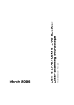
Layout and Connections
The general layout of PASS is shown above, with connectors
identified.
Pangolin includes connectorized ribbon cables with PASS. These
ribbon cables can be used directly, allowing minimal effort to
integrate PASS within a projector. When ribbon cables have a red
stripe on one side, the red stripe indicates the side of the cable
associated with pin 1.
11
J801: Projector-Signal-Input
The Projector-Signal-Input to PASS may come directly from the DB25 input on the projector, or may come after projector internal
electronics that condition the color signals (for example, allow
adjustment of intensity for each color or scanner axis inversion and
rotation). When PASS is used for direct projector input, a simple
crimp-on DB-25 connector may be used, and crimped onto the
Projector-Signal-Input ribbon cable provided with PASS.
J802: Projector-Signal-Output
The Projector-Signal-Output connector on the PASS board should be
parsed out into pairs of signals, and then directed to various
components within the projector. The signals and recommended
connections are discussed below. Note that since this is an IDC
connector, the pin numbers do not correspond to the ILDA pin-out on
a DB-25. HOWEVER, if you crimp a DB-25-connector onto the
output ribbon cable, then the pins will correspond directly to the
ILDA pin-out. This is because the pin designations of a DB-connector
are “in-line” while the pin designations of an IDC connector are
“even and odd”.
Pins 1 and 2 correspond to the X+ and X- signal respectively.
These should be connected to the X+ and X- input on the X-axis
scanner amplifier.
Pins 3 and 4 correspond to the Y+ and Y- signals respectively.
These should be connected to the Y+ and Y- input on the Y-axis
scanner amplifier.
Note: There should NOT be a connection to the “signal ground” of
any scanner amplifier. The only “ground” connection to the scanner
amplifier (or amplifiers) should be from the power supply itself.
Connecting to the “signal ground” on a scanner amplifier will
introduce a ground loop, which may cause distorted images. See the
“Power and X-Y Position Signal Connections” on the following
pages.
Pins 5 and 6 correspond to the Intensity/Blanking+ and
Intensity/Blanking – signals respectively. These may be used for a
single-color projector or projectors that use a PCAOM for color.
12 PASS Installation and User Manual
Pins 7 and 8 correspond to the Projector Interlock loop pins 4 and
17 from the ILDA connector. Note that PASS will interrupt this
interlock signal loop in the event of a critical fault and when
power is insufficient, therefore it is MANDATORY that
projector manufacturers implement an interlock scheme that
makes use of these signals. Ideally this interlock loop should
interrupt power to the lasers themselves, thus, in the event of a
major problem, PASS can interrupt power to the lasers.
Alternatively the interlock loop may be routed to a SEPARATE
shutter placed just before the X-Y scanners and after the PASS
light sensor.
Pins 9 and 10 correspond to Red+ and Red – color signals
respectively. These should be connected to the RED input on a
PCAOM driver or directly to a laser diode driver.
Pins 11 and 12 correspond to Green+ and Green – color signals
respectively. These should be connected to the GREEN input on a
PCAOM driver or directly to a laser diode driver.
Pins 13 and 14 correspond to Blue+ and Blue – color signals
respectively. These should be connected to the BLUE input on a
PCAOM driver or directly to a laser diode driver.
Pins 15 and 16 correspond to Deep Blue+ and Deep Blue – color
signals respectively. These are most often not used by modern
RGB laser projectors and thus, can be left unconnected. If they are
used, they should be connected to the DEEP BLUE input on a
PCAOM driver or directly to a laser diode driver.
Pins 17 and 18 correspond to Yellow+ and Yellow – color signals
respectively. These are most often not used by modern RGB laser
projectors and thus, can be left unconnected. If they are used, they
should be connected to the YELLOW input on a PCAOM driver
or directly to a laser diode driver.
Pins 19 and 20 correspond to Cyan+ and Cyan – color signals
respectively. These are most often not used by modern RGB laser
projectors and thus, can be left unconnected. If they are used, they
should be connected to the CYAN input on a PCAOM driver or
directly to a laser diode driver.
Note that for the color signals above, ideally, any Laser Diode Driver
should have differential input, and you should connect both the + and
– color signals from the PASS board directly to those drivers.
Pins 21 and 22 correspond to the Z+ and Z – signals respectively.
In most cases, laser projectors do not use these signals directly and
13
in fact, when used with certain pieces of Pangolin software, these
signals correspond to a Safety Coordinate System. It is
recommended that these be left unconnected.
Pin 23 is connected to the ILDA input connector pin 12. This
signal is reserved by ILDA for a light sensor output, but it is
essentially unused by all manufacturers. It is recommended that
this pin be left unconnected.
Pin 24 is connected to the ground connection of PASS. It is
recommended that this only be used as a ground reference for the
shutter driver, and nothing else.
Pin 25 is the main Shutter output. Under normal circumstances the
state of this signal will correspond directly to pin 13 on an ILDA
input connector. However, in the event of a major fault, PASS will
forcibly close the shutter using this signal. It is therefore
MANDATORY that this be connected to a shutter driver. For
maximum safety, the shutter should be a fast type of shutter, and
one that also will fail-safe. This means that in the event of a
mechanical or electrical failure of the shutter, it will remain closed
due to the mechanical design of the shutter. Pangolin highly
recommends shutters manufactured by the company called
nm Laser Products (http://www.nmlaser.com).
J803: Scanner Position and Light Detector Inputs
Pin 1 provides +5V output, which should only be connected to the
PASS light sensor.
Pin 2 is the PASS light sensor input, which ranges from 0V to
+5V.
Pin 3 and Pin 5 correspond to the Signal Ground connection of
PASS. Pin 3 should be connected to the PASS light sensor. Pin 5
may or may not be connected to the scanner amplifier, depending
on circumstances described below.
Pin 4 corresponds to the X Position Signal. This should be
connected to the X-axis scanner amplifier.
Pin 6 corresponds to the Y Position Signal. This should be
connected to the Y-axis scanner amplifier.
14 PASS Installation and User Manual
J804: Control Panel Signals
PASS may be controlled by, and may illuminate LEDs on an external
control panel that is connected to PASS. Below is a description of the
control panel connections. When PASS is not connected to an
external control panel, then PASS will automatically reset into a
“ready” state shortly after power up. When PASS is connected to an
external control panel, then PASS will not power up in a “ready” state
and instead, will wait for the “Manual Reset” from the control panel.
Note that some jurisdictions including the U.S.A. require a manual
reset in order to activate the projector after power up. The PASS
control panel connector may be used to help facilitate this feature.
Also note that the signals presented to this connector are generally
connected directly to PASS logic circuits. The signals are not
protected from ESD or other electrical faults. For that reason, it is
recommended that any external signals that are connected to this
connector be short (i.e. don’t connect a 30 meter long cable from the
external box to the PASS board…)
Pin 1 is the active input that corresponds to an external Emergency
Stop (ESTOP) switch, such as a pushbutton or red “mushroom”
type switch. When this pin is connected to Pin 2 (ground), ESTOP
is activated. When Pin 1 is left floating, then ESTOP is inactive
and the projector will be allowed to operate normally.
Pin 3 is the active input that corresponds to a Manual Reset. This
may be connected to pin 4 (ground) through a momentary
pushbutton switch or a key-switch.
15
Pin 5 is an active input that indicates that a control panel is being
used. Pin 5 must be connected to Pin 6 when a control panel is
used. If Pin 5 is not connected to Pin 6, then PASS will not wait
for a manual reset when power is first applied.
Pins 7 and 8 provide +5V to the control panel. These may be used
in conjunction with LEDs on the control panel.
Pins 9 and 10 correspond to Ground. These may also be used in
conjunction with LEDs on the control panel.
Pin 11 is an output, which corresponds to the horizon detector
within PASS. If this signal is LOW, it indicates that the Y position
is below the horizon (within the audience area). If this signal is
HIGH (approximately 4 volts), it indicates that the Y position is
above the horizon. This signal may be routed through a resistor to
an LED or pair of LEDs (bi-color pair) to give an indication on the
control panel as to where the beam is within the Y space.
Pin 13 is an output, which corresponds to the velocity detector
within PASS. If this signal is LOW, it indicates that the beam
velocity is OK, and that PASS will not actively suppress laser
output because of velocity (PASS may suppress laser output for
other reasons however). If this signal is HIGH (approximately 4
volts), it indicates that the beam velocity is too slow, and that
PASS will actively suppress laser output. This signal may be
routed through a resistor to an LED or pair of LEDs (bi-color pair)
to give an indication on the control panel as to the disposition of
the velocity.
Pin 15 is an output, which corresponds to the light detector within
PASS. If this signal is LOW, it indicates that the light that is
detected by PASS is above the “Maximum Safe Laser Power”
threshold setting. If this signal is HIGH (approximately 4 volts), it
indicates that the light detected is below the “Maximum Safe
Laser Power” threshold setting. Under ordinary circumstances,
this will never be LOW. This signal may be routed through a
resistor to an LED or pair of LEDs (bi-color pair) to give an
indication on the control panel as to the disposition of the light
detected by the light sensor.
Pin 17 is an output, which corresponds to whether or not PASS is
“ready”. Once PASS has given a “armed” indication on Pin 19,
and then once the “Manual Reset” is activated (by connecting Pin
3 to Pin 4), this signal will go HIGH, indicating that PASS will
allow color signals to flow through the PASS board to the internal
laser projector components. This signal will remain HIGH as long
16 PASS Installation and User Manual
as there are no major faults detected, such as a Power Supply fault,
Light Detector fault, other detectable major fault, or ESTOP being
activated. This signal may be routed through a resistor to an LED
or pair of LEDs (bi-color pair) to give an indication on the control
panel as to whether or not PASS is active.
Pin 19 is an output, which corresponds to whether or not PASS is
ready to be activated (“armed”). If this signal is HIGH, it indicates
that the power supply is OK, ESTOP is not activated, and light is
not detected and thus, PASS may be activated by performing a
“Manual Reset”. This signal may be routed through a resistor to an
LED or pair of LEDs (bi-color pair) to give an indication on the
control panel as to whether or not a Manual Reset can be
performed. If used, this LED should ideally be placed near the
“Manual Reset” push button or keyswitch.
Pin 12 is an output, which corresponds to whether or not the
computer feeding the ILDA input has commanded that light come
out of the laser projector or not. If this signal is HIGH, it indicates
that the light that PASS has detected that the computer has
requested more than approximately 50% beam power from the
computer. If this signal is LOW, it indicates that the computer is
commanding 50% or less beam power from the computer. This
signal may be routed through a resistor to an LED or pair of LEDs
(bi-color pair) to give an indication on the control panel as to
whether or not the computer has commanded light to come out of
the projector.
Pin 14 is an output, which corresponds to the condition of the
power supply, both within PASS and supplying the scanner
amplifiers. If this signal is HIGH, it indicates that the power
supply feeding the scanner amplifiers is 19 volts or higher. It also
indicates that all of the power supplies within PASS itself are also
within their acceptable ranges. If this signal is LOW, it indicates
that there is a power supply problem of some kind. This signal
may be routed through a resistor to an LED or pair of LEDs (bicolor pair) to give an indication of the state of the power supplies.
17
Status LED signals on the Control Panel connector
Pin 16 is a “Status LED number 1”. If this signal is LOW, it
indicates that a power supply fault has been detected.
Pin 18 is a “Status LED number 2”. If this signal is LOW, it
indicates that the PASS light sensor detected a light level that
exceeded the “Maximum Safe Light Level” while the Y position
was below the horizon.
Pin 20 is a “Status LED number 3”. If this signal is LOW, it
indicates that PASS tried to extinguish light from coming out of
the projector, but that the PASS light detector still detected light
output. This would occur if a PCAOM or Laser Diode Driver
continued to output light after being told not to. This would also
occur if the “Minimum light level” adjustment of PASS is not set
correctly. And finally, this might also occur if PASS did not detect
light coming out of the computer even though the computer
commanded light output. This would indicate either a laser failure
or light detector failure.
Note that unlike the other LED outputs on the control panel
connector, the “Status LED” outputs will “latch” in the event that a
fault is detected. They will remain in the latched state until a Manual
Reset occurs. This allows you to determine the cause of any detected
faults.
The “Status LED” signals may be routed through a resistor to an LED
on the control panel to give an indication of any faults that have been
detected.
18 PASS Installation and User Manual
PASS Power and X-Y position signal connections
PASS monitors the power supplies that feed the scanner amplifiers.
This voltage can be between +/-20 volts and +/- 30 volts. The manor
in which you connect PASS to the power supply and to the scanner
amplifiers depends heavily upon whether you are using two separate
single-axis scanner amplifiers, or one dual-axis scanner amplifier.
If you are using two separate single-axis scanner amplifiers, the
recommended connections are shown below:
Note that each scanner amplifier, as well as the PASS circuit board
itself must each have their own power wires going back to the power
supply. These wires should all meet at the power supply itself. If you
have two power supplies (one for +24V and the other for –24V) then
these power supplies should establish a central connection where all
wires meet. This is called a “single-point grounding scheme. Wiring
the power supply in any other way will cause a ground loop, which
may cause distorted images during projection.
19
Also note that when using two separate single-axis scanner
amplifiers, you run only the POSITION signal to the PASS position
input. DO NOT connect any additional ground wire from each
scanner amplifier to the PASS board. Doing so would introduce a
ground loop, which may cause distorted images.
If you are using a one dual-axis scanner amplifier, the recommended
connections are shown below:
Since there is only one scanner amplifier in this case, the scanner
amplifier is connected directly to the power supply. If you have two
separate power supplies (one for +24V and one for –24V), these can
be connected at the scanner amplifier itself. The PASS board is also
connected at the scanner amplifier itself.
Note that in this case, it is permitted to connect a separate “position
signal ground” from the scanner amplifier to the PASS board if you
wish.
20 PASS Installation and User Manual
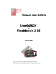
PASS Switches
PASS includes a number of switches that must be configured to
customize operation to a particular projector or projection scenario.
Below you will see the PASS board and location of the switches. The
operation of each switch is described below.
21
With the PASS board in the physical orientation shown above,
Switch 4 is at the top. When this switch is moved to the left (on),
the light sensor input is ignored. You should move the switch to
this position only during the setup operation described below,
or in those rare circumstances that PASS could legitimately be
used without a light sensor. When this switch is moved to the
right (off), the light sensor input is monitored, and the maximum
level of safety is provided.
With the PASS board in the physical orientation shown above,
Switch 3 is next in line. When this switch is moved to the left (on),
the Horizon control is monitored and PASS will only allow static
or slow beams above the horizon. If there is a slow-moving, or
non-moving beam below the horizon, it will be extinguished by
PASS. When this switch is moved to the right (off), the Horizon
control is ignored, and PASS will not allow a slow-moving or nonmoving beam anywhere within the entire scan field.
With the PASS board in this orientation, Switch 2 is next in line.
This switch controls the interpretation of an advanced feature of
PASS called the S-coordinate. At this time, we recommend this
switch be placed in the left position (on).
With the PASS board in this orientation, Switch 1 is on the
bottom. This switch controls where PASS gets the light sensor
signal. ILDA pin 12 is defined by the ILDA standard as possibly
providing feedback from a light sensor. However, since the vast
majority of projectors do not use this part of the ILDA standard,
we recommend that this switch be moved to the right (off).
22 PASS Installation and User Manual
PASS Adjustment Potentiometers
As was the case with the switches, PASS includes five potentiometers
that must be adjusted to customize the operation of PASS to a
particular projector or projection scenario. Below you will see the
PASS board and location of the five adjustment potentiometers. The
operation of each potentiometer is described below.
The Minimum Velocity controls the minimum speed that the beam
is required to sweep, in X and/or Y, in order to be considered to be
safe. At the factory, Pangolin sets this to around 5 radians per
second. Note that the scale of this control (in radians per second)
depends on the actual position scale factor of the scanner amplifier
being used. Turning this control clockwise increases the minimum
velocity (requiring faster scanning in order to be considered safe).
23
The Dwell Time controls the time that a beam may remain at or
below the minimum velocity, before PASS extinguishes the beam.
At the factory, Pangolin sets this to around 1.5 milliseconds, but
you must adjust this yourself by using a calibration procedure, such
as the one described below. Turning this control counter-clockwise
reduces the Dwell Time, and turning this control clockwise
increases it. The Dwell Time can be adjusted between
approximately 100 microseconds and 10 milliseconds.
The Horizon adjusts the “Protected Area” (if Switch 3 is moved to
the “on” position). At the factory, Pangolin sets this control to
approximately the center of the vertical scan field, but this may be
adjusted clockwise or counter-clockwise to set the horizon of the
protected area as desired. Note that this control is very sensitive to
rotation. You will not need to turn this control very much to
explore the entire vertical area. Also note that the horizon
adjustment is completely ignored if Switch 3 is turned off. (See the
section about PASS Switches for more information.)
The “Maximum Safe Beam Power” adjustment controls the
maximum power that can be allowed into the “Protected Area”. For
example, if the beam is scanning within the audience area, PASS
will monitor the beam power and make sure that this beam power is
not exceeded. If the beam is not scanning within the “Protected
Area” (for example, above the horizon), then this control is ignored
and full-power beams can be projected overhead.
The “Minimum Power” adjustment controls the minimum light
level that is detectable by the light sensor. Generally this is
adjusted so that no light is detected by PASS when the laser is off.
You can adjust the “Maximum Safe Beam Power” and “Minimum
Power” adjustments by looking at D208 “Light Sensor State” bi-color
LED on the PASS board.
Also note that the “Maximum Safe Beam Power” and “Minimum
Power” adjustments are ignored if the switch 4 is turned “on” (see
switches on page 20).
24 PASS Installation and User Manual
PASS Adjustment Procedure
NOTE: The information contained in this section must be
understood and followed very carefully in order to ensure that
PASS operates correctly, and to minimize the risk of an unsafe
laser exposure.
Since the procedure described below involves projecting patterns into
an area that an audience will eventually occupy, and since the light
levels experienced during adjustment procedure may exceed the MPE
under some circumstances, it is highly recommended that you
perform the procedure below when the venue is only occupied by
trained technical staff, and communicate very clearly when the laser
will be turned on so that staff will know how to react. To avoid the
possibility of illuminating people who may not understand the
technology or potential risks that a laser projector may present, the
adjustments and procedures described below should preferably be
done in a laboratory environment, not in the venue where personnel
(for example waitresses, etc.) may be walking around before the
venue opens.
Step 1: Adjust the Horizon
(whether you will ultimately use it or not)
During this first test, it is important to use the lowest amount of laser
power possible. This will reduce the chance of illuminating personnel
that might be in the room during these tests. For the next few tests
and adjustments, the beam power is best reduced by using the
software brightness level setting – rather than potentiometers that
might reside on the back of a laser projector.
First, set PASS Switch 3 to “Protect only the bottom portion” (switch
moved to the left, if the board is physically oriented as shown on Page
20). Also, set Switch 4 to “Light sensor not used” (switch moved to
the left.) These switch positions are necessary for the next few
adjustments.
Next, output a slow-moving circle (for example, somewhere in the
1Hz to 5Hz range) using a function generator or abstract generator
feature of the software. The circle should be somewhere between 50%
and 100% size for this test. Note that while doing this and if PASS is
not set correctly, the laser beam will probably be allowed to enter the
audience area. Therefore it is once again important to make sure there
are no untrained or non-technical personnel present in the room
during this setup.
25
At this point and with this kind of pattern being projected, you should
see that – while the beam is above the audience area, it is visible, and
while the beam is within the audience area, it is extinguished. If you
do not see this, then it is possible that the Horizon potentiometer is set
so far in one direction, that PASS thinks the entire scan field is above
the horizon. In such a case, turn the Horizon potentiometer several
turns clockwise, and then several turns counterclockwise, until you
see that there is an area where the beam is blanked. If you never reach
a point where the beam is not extinguished, then stop right there and
make sure PASS is wired correctly – particularly with respect to the
scanner position signals.
Next, adjust the Horizon potentiometer clockwise, and counterclockwise, to position the area (horizon) such that the beam is
extinguished when it is in the audience area.
Once this is done with the slow-moving circle, COLLAPSE the Y
axis (change Y size to zero in the software), which will project
essentially a slow-moving horizontal beam – centered on the Y-axis.
You will want to make sure that the beam is extinguished in this
configuration, because it is important when the projector has no
scanning input (i.e. X and Y projector inputs at zero) that no light will
come out of the projector.
Now adjust the Y position control in the software upward, to the point
where the beam becomes visible again. You want this to be at least
2% upward. If the beam becomes visible at 1% upward position on Y,
adjust the Horizon control again to extinguish the beam.
Once the Horizon is verified above, return the Y position control in
the software to 0.
Step 2: Determine the Maximum Beam Power
allowable in the audience area
Now that the PASS horizon has been adjusted, it can be used to aid in
preparing to evaluate the maximum laser power that will be allowed
in the audience.
At this point it will be necessary to configure the software to output a
stationary, non-modulated laser beam. In LD2000 this can be done by
going to the Abstract Generator (menu SFX/Abstract Generator), and
then reducing the size of the default abstract to zero, and then
pressing OK.
If you have adjusted the horizon properly, you should see NOTHING
coming out of the laser projector. Otherwise, go back and repeat the
26 PASS Installation and User Manual
steps above, ensuring that the Horizon potentiometer is adjusted
properly.
Since the point is to determine the maximum amount of laser power
that will be safe in the audience, this should be done with any
projector-based power-level adjustments defeated. For example, if the
projector has potentiometers (or digital adjustments) accessible from
the rear, that can be used to reduce the beam power, these adjustments
should be set all the way at maximum, so that the power level coming
out of the laser projector is entirely controlled by the software input.
Now – in the Projector Settings dialog box, make sure that the
brightness level is turned down – perhaps to 10%.
Slowly move the Y Position control upward, until the beam hopefully
becomes visible. If the beam does not become visible after a
substantial upward movement of Y Position, then adjust the
brightness level upward until a beam is seen.
Now, using a laser power meter that has a 1 square centimeter (or
approximately 11mm round) detector, place the detector of the power
meter into the stationary beam – AT THE CLOSEST POINT OF
AUDIENCE ACCESS. It might be handy to mount the detector head
of the power meter onto a tripod stand, so that it can be held into the
stationary beam.
The laser beam should be larger than the 1 square centimeter power
meter detector area. If it is not, then you will need to increase the
divergence of the laser beam, for example, using one of Pangolin’s
SafetyScan lenses. (A beam smaller than 11mm round in the audience
will certainly not be safe, unless the power is around 10 milliwats…)
When the laser beam is larger than the 1 square centimeter active area
on the power meter, then the power meter will read in terms of Watts
Per Square Centimeter (also known as “irradiance”), instead of Watts
(also known as “radiant power”). This is an important concept that
must be understood. The laser safety standards are based on
irradiance, not radiant power!
Using the software brightness control, increase the beam power
upward and upward and upward until the laser power meter reads the
desired level of irradiance – according to the MPE that you are trying
to accomplish. Although PASS allows for a large degree of
adjustment, laser industry best practices generally assume that the
irradiance will be no greater than 10 milliwatts per square centimeter
for a 1 millisecond pulse width described below.
27
Now that you have determined the maximum brightness level that the
software can output to accomplish the desired irradiance, you should
write this down on a piece of paper, or otherwise record it. For
example, this might be a brightness level of 27%. This means that you
will need to paint a brightness level of 27% into the Beam
Attenuation Map, or use other software features to ensure that the
beam power never exceeds the maximum safe power level determined
in this step.
Step 3: Enable the light sensor,
and adjust the Maximum Beam Power potentiometer
Adjust the Maximum Beam Power potentiometer on PASS, many
turns clockwise. The idea is to set this to a level that won’t
immediately trip once you enable it using Switch 4.
Now, go to the Abstract Generator and increase the size to project a
circle. Any other pattern may be projected, but it’s best to keep the
pattern simple.
If you have done everything correctly and followed the instructions
carefully, at this point you should see a circle or pattern projected at
what is essentially the maximum power that it will ever be in the
audience.
Next, using the brightness level setting in the software, increase it a
one percent past the level determined above. For example, if the
maximum safe power was determined to be 27% brightness, you
should increase the brightness level setting to around 28%. This
should output a power level a bit higher than the maximum
determined in the step above.
Next, enable the light sensor by moving PASS Switch 4 to the “Light
sensor is used” setting (switch moved to the right).
Next, slowly turn the Maximum Safe Power potentiometer
counterclockwise, until PASS “trips”. Basically what you are doing in
this adjustment is bringing the threshold down to the point where
PASS will trip if it detects more beam power than was determined to
be safe above.
Once PASS has “tripped”, it will need to be reset, either using the
Manual Reset pins on the control panel connector, or by cycling
power to the projector.
Before resetting PASS using control panel pins (or cycling power to
the projector), reduce the brightness level setting in the software back
to the level determined above (for example, 27%).
28 PASS Installation and User Manual
Once the projector is running again, you can verify the “trip” level, by
adjusting the brightness level upward until it trips. We also
recommend that you run a number of test patterns and show program
material with the brightness set to the maximum safe power
determined above (i.e. 27%). If the projector occasionally trips, then
you might want to examine any filter or combiners used to “flatten”
the spectral response curve of the light detector used in your
projector. If PASS trips repeatedly, you may need to reduce the
brightness level determined above (for example to 26% or so)…
Step 4: Set PASS Switch 3 to the desired position
If it is your intention for PASS to protect the entire scan field, then
now would be the time to move Switch 3 “Protect entire scanfield”
position (to the right). Otherwise you can simply leave the switch
where it is.
Preparing to perform further measurements and adjustments
At this point you will be adjusting the velocity detector and dwell
timers inside PASS. To do this, connect a fast photodiode to an
oscilloscope. The photodiode should be the amplified type, so that the
oscilloscope will show voltage as a result of light entering the
detector. The Thor Labs model PDA100A is a good choice for an
amplified photodiode.
A 7mm aperture must be placed in front of the photodiode entrance
aperture. This might be done by cutting a 7mm hole in a piece of
“Black Wrap” foil, and then placing this over the entrance aperture.
The 7mm pupil allows the photodiode to measure the pulse width as a
scanning beam crosses a 7mm dilated pupil.
The photodiode should be placed on a tripod, so that it can be moved
into the beam path to perform safety-related measurements.
Once the photodiode is prepared as described above, use a function
generator or software’s built-in ability to project a circle. The circle
should preferably be continuous, and non-modulated. In LD2000 this
is easily accomplished using the Abstract Generator. (Just go to
SFX/Abstract Generator, and click OK.) The size of the circle should
be such that it scans within the area where the audience will reside.
As with some of the tests above, during these tests, it is important
to use the lowest amount of laser power possible. This will avoid
overloading the photodiode and also reduce the chance of
illuminating personnel who might be in the room during these
tests.
29
Move the tripod and photodetector such that the circle scans across
the 7m aperture – AT THE CLOSEST POINT OF AUDIENCE
ACCESS – and look at the output on the oscilloscope. Preferably, the
photodiode is positioned roughly in the center of the beam path as it
scans past the detector. This should also be the brightest part of the
beam. You should be careful, and be aware that photodiodes have
shiny surfaces which can create mirror-like back-reflections.
Therefore you must be very careful while placing the photodiode into
the beam path, that the reflected stray beam will not accidentally wind
up targeting personnel or an undesired location.
Adjust the voltage input and time setting on the oscilloscope so that
you can measure the height (i.e. maximum voltage) of the pulses.
During this part of the test, it is very important to make sure that the
photodiode is not overloaded with light, and merely delivering a
“saturated” maximum voltage to the oscilloscope, as this will
artificially lengthen the pulse width. The PDA100A photodiode has
an attenuator dial on the side to adjust the gain. Make sure that this
gain setting is adjusted properly, so that the photodiode is not
overloaded.
Step 5: Adjust the Minimum Velocity potentiometer
Once you have a reliable voltage measurement, the pulse width is
determined at the “full width at half maximum” points on the
waveform. For example, if the voltage waveform slopes from 0 volts
upward to 4 volts, and then downward to 0 volts, essentially this
means that the pulse width is the amount of time that the pulse is
greater than 2 volts.
Since laser industry best practices are that audience scanning shows
are done using the assumption of a 1-millisecond maximum pulse
width, you should compare this against the pulse width seen on the
oscilloscope. If the pulse width is shorter than 1 millisecond, then you
will need to slow down the function generator (or Pangolin software
abstract generator) until you get to a pulse width of 1 millisecond.
Generally, PASS should be adjusted to extinguish the laser beam for
pulse widths greater than 1 millisecond. If you are able to slow down
the function generator to obtain longer pulses, then this means that
the MINIMUM VELOCITY adjustment on PASS must be increased
(turned clockwise).
Step 6: Adjust the Maximum Dwell Time potentiometer
Now that the Minimum Velocity adjustment has been setup, you can
move to the next part of the test, which ensures that the Maximum
Dwell Time is adjusted properly. To do this, change the test pattern
30 PASS Installation and User Manual
from a circle to a Quadrature Squarewave. (A Quadrature Squarewave
is a pattern where the beam stops in four places, and jumps very
quickly from place to place. The Abstract Generator in LD2000 has a
drop-down list box where you can select the waveform that will be
used.)
Move the photodiode and tripod into one of the corners of the
quadrature squarewave, taking all of the precautions mentioned
above. Adjust the voltage level on the oscilloscope, and adjust the
attenuator dial on the photodiode to ensure that you have a reliable
voltage measurement.
As described above, determine the pulse width at the “full width half
maximum” points on the waveform. If the pulse width exceeds 1
millisecond, adjust the MAXIMUM DWELL TIME potentiometer
counterclockwise.
31
Using PASS with a light sensor
When PASS is used with the "LIGHT SENSOR USED" switch
setting, then a light sensor must be connected to J803 Pin 1, Pin2, and
Pin 3.
When a light sensor is not used, J803 Pin 2 should be connected to
Pin 1. Note: it should be understood that using PASS without a
light sensor should only be allowed if you are using the PASS
hardware as a simple scan-fail safeguard AND if the laser power
is low enough to justify this AND if you implement additional
safety-related systems down-stream from the PASS hardware.
Contact Pangolin for more information if you are interested in
using PASS without a light sensor.
When used, a light sensor must be installed within the beam path of
the projector. Generally we recommend that the light sensor be placed
before the final shutter, but it may also be placed after, as long as the
final shutter opens faster than around 1/20th of a second.
Generally the light sensor is fashioned as a glass window that is used
to "sample" the outgoing laser beam at a 45-degree (or so) angle, and
direct a small portion of the laser beam to light-sensitive material.
The light sensor used with PASS must be a relatively fast sensor –
one that is able to react as quickly as the light can be modulated.
Generally this means that the light-sensor must be based on silicon
photodiode or silicon PIN photodiode type technology.
If the projector is a multi-wavelength projector (e.g. an RGB
projector), and a single light sensor is used in the combined beam
path, then the light sensor must have an additional “spectral
flattening” filter to make the light sensor provide the same output for
all wavelengths. This is because the safety standards treat all visible
wavelengths the same. Since silicon detectors have a peak response in
the near infrared and since their response tends to trail off toward the
visible blue spectrum, this filter appears to the naked eye as a bluish
piece of glass – allowing light in the blue end of the spectrum to pass
freely, while attenuating longer wavelengths more progressively.
These tend to be specialized filters, generally matched to a particular
photodiode, and therefore we have not found a place that sells just the
filter by itself.
An alternative to using a single sensor in the combined beam path
would be to put individual light sensors after each separatewavelength laser, and sum the output of all of the light sensors so that
32 PASS Installation and User Manual
the total output voltage sent to PASS corresponds linearly with
wattage (i.e. delivers the same amount of voltage for the same amount
of power from each separate wavelength).
The output of silicon photodiodes cannot be directly connected to
PASS. Instead the photodiode output must be amplified, and turned
into a zero-to-5-volt analog signal, where zero volts represents no
light being detected and 5 volts represents the maximum voltage
delivered to PASS. Note that PASS provides a connector with 5 volts,
so this is where the light sensor and amplifier can get its power.
Since PASS has adjustments for MINIMUM POWER and
MAXIMUM SAFE POWER (see page 22), the output of the sensor
does not need to reach all the way to 5 volts when maximum light is
coming out of the projector. Likewise, the sensor may deliver 5 volts
even before the maximum light power level is reached. Any
maximum-light-output scale factor can be used as long as around 4
volts or less represents the maximum safe light level for audience
scanning (which would generally be lower than 1 watt, but could be
more depending on the distance of the projector to the audience and
other factors).
Under the most ideal circumstance, the photodiode should be
amplified with a logarithmic amplifier (also called "log-amp"),
because when this is done, the voltage output from the amplifier will
correspond to light power (i.e. watts), not just light intensity.
However, a simple op-amp amplifier may be used, as long as it has
enough dynamic range that a few milliwatts of power delivers a
detectable voltage level (and can satisfy the "MINIMUM POWER"
adjustment) and also maximum safe light level is reached before
around 4 volts.
Presently, the only ready-made product that is readily available on the
market, which has a silicon detector with the “spectral flattening”
filter attached and logarithmic amplifier board is the model SEL033
detector with model F "flat response" filer, and model A430
amplifier, all available from International Light Technologies
corporation. Note that these components are generally not stocked
items, and normally they have to be pre-ordered from the company.
Also note that these are large and bulky, so they may not be
appropriate for compact projectors. And finally the combination of
these parts does not constitute a complete light sensor ready to be
used in a laser projector. The sampling window and mounting
hardware are additional items that need to be fashioned within the
projector to create a whole light sensor package.
33
Using a light sensor with PASS can be tricky. When you enable the
light sensor feature in PASS, everything must be at least ready to
operate correctly. Otherwise PASS will detect problems and “trip” –
forcibly shutting the projector down, requiring either a manual reset
(i.e. by briefly shorting pin 3 to pin 4 on the Control Panel Connector)
or the power being re-cycled.
PASS will forcibly shut the projector down under the following
critical circumstances:
• A voltage level less than the "MINIMUM POWER" adjustment
indicates, being detected when the software (via the color lines
on the ILDA connector) commands light to be coming from the
projector.
• A voltage level greater than the "MINIMUM POWER"
adjustment indicates, being detected when the software
(through the color and intensity lines) indicates that the output
is supposed to be blanked.
• A voltage level greater than the "MAXIMUM SAFE POWER"
being detected when the beam is projected within an audience
area. Of course the audience area may be the entire projected
area, or only the lower portion of the scan field, depending on
the "PROTECTED AREA" switch setting.
Using the light sensor with PASS affords the maximum level of
protection, because if the laser power is increased above the
MAXIMUM SAFE POWER within the designated audience area (i.e.
the entire scan field, or only below the horizon depending on a switch
setting) PASS will immediately shut down the laser projector.
Therefore Pangolin considers it to be mandatory that a light
sensor be used in safety-critical situations.
Because setting up PASS with a light sensor can be tricky and may be
frustrating to get it working perfectly, we recommend clients work
closely and directly with Pangolin during this phase of projector
integration.
34 PASS Installation and User Manual
Application of this product within the United States
The mere act of putting PASS inside a laser projector will not
instantly and automatically allow it to be used within the United
States for audience scanning. For that to occur, both the projector and
the show will need a variance, in exactly the same way that both the
projector and show would need a variance if it were not used for
audience scanning. However, obtaining a variance for an audiencescanning projector and even an audience-scanning show takes quite a
bit of time and skill on the part of the variance applicant.
In recent years, PASS has become a well-known name brand product,
and the decades-long-employees (founding fathers if you will) of the
US Center for Devices and Radiological Health know PASS by name.
Nevertheless, simply mentioning PASS by name, in your variance
application, should not be expected to quickly open any doors… An
audience-scanning variance application must describe what PASS
does, along with the other projector features (for example, no doubt
including a lens installed either inside or outside the laser projector to
increase divergence) to help ensure audience safety. Finally, the
audience-scanning variance must include documentation on how the
projector is setup, how measurements are performed and verified, and
how the projector is used at each event in ways that ensure audience
safety. For the most part, an audience-scanning variance application
covers the same things that a more ordinary variance application
covers, but it covers them in a more rigorous way.
While drafting variances for audience scanning, and for general
knowledge of what PASS does and how it works, some people have
found it handy to refer to the Patents on PASS. The issued US patent
can be found on the USPTO web site, or on Google Patents. It is
called "Laser projector safety monitoring system" and is covered by
US Patent number: 7,756,174. In Europe, the patent application can
be found at the World Intellectual Property Organization web site. It
is called "Laser projector for audience scanning" and is covered by
number: EP20060733773. In Australia, the issued patent can be on
the IP Australia web site. It is called “Laser projector for audience
scanning” and is covered by Australia Patent number 2006206400.
For those who do not have a lot of skill with filling out US
Government paperwork, we recommend a laser safety consultant,
such as Greg Makhov, Casey Stack or Jay Parkinson. Within Europe
and the United Kingdom, we recommend James Stewart.
35
Ensuring the continued safe operation of projectors
Although PASS monitors the real-time activity of the laser projector
power supply, scanner velocity, optional laser output power and
optional control panel signals, PASS, by itself, cannot ensure the
safety of a laser show. Divergence-modifying elements (such as the
SafetyScan lens) are actually more critical to audience safety than is
PASS. This is because under normal circumstances, (i.e. when
everything is working properly and you are using proper divergence
and show presentation techniques) PASS plays only a secondary and
passive role in audience scanning safety, whereas a divergence
increasing lens and proper show performance techniques play a
primary and continuous role in audience scanning safety.
And although the PASS hardware has been designed to be self-testing
and employs redundant circuitry, it is ultimately an electronic circuit,
and it is conceivable that, under certain rare circumstances, the PASS
circuitry could fail in such a way that it would not prevent an unsafe
laser exposure. This is why the Professional Audience Safety System
is not considered to be only the PASS hardware circuit board by
itself, but rather an entire safety system, which includes the external
light sensor, external shutter, and projector interlock. It is only when
all of these things are used together and properly adjusted, that there
will be sufficient redundancy and monitoring to reduce the risk of an
unsafe laser exposure.
Of course the adjustments on PASS must be configured properly, for
the scanning velocity and dwell time as well as the projection horizon
(if used). Moreover, the light-sensor-related adjustments on PASS
must be configured to monitor the minimum beam power of the laser
(to ensure proper light sensor and laser diode driver operation) as
well as the maximum beam power of the laser (to ensure that
exceeding a safe power level will be detected by PASS).
And finally, it is clear that in order to ensure continued and repeated
safe performance, tests of the entire projection system must be
conducted before each show performance (for example nightly), to
make sure all elements of the projector and computer system feeding
the projector as well as the PASS hardware itself are all working as
expected. At a minimum, these tests should involve the projection of
test patterns specifically designed to demonstrate that PASS and other
safety features are working properly (both inside the audience area
and outside), and that PASS will properly extinguish the laser beam
when needed, as well as properly disabling the projector (i.e.
36 PASS Installation and User Manual
“tripping”) if the Maximum Beam Power is exceeded. (Please contact
Pangolin if you need assistance in the creation of such test patterns.)
The performance of these tests, along with any measurable analytical
results should be logged, and the log should be permanently kept in a
safe place, so that it can be reviewed later if needed.
If any of the tests mentioned above provoke unexpected results, the
projection system should not be used for the laser show performance
until the entire projection system has been examined and any problem
discovered has been remedied.
37
Board layout and Status LEDs
38 PASS Installation and User Manual
Dimensions and mounting holes
39
License Agreement and Limited Warranty
THIS IS A LEGAL AGREEMENT (the "Agreement") between you
and Pangolin Laser Systems, Inc. ("Pangolin") as manufacturer and
licensor of the Professional Audience Safety System (PASS). This
Agreement provides you with the authorization to use PASS subject
to the terms and conditions herein. If you do not agree to all the terms
and conditions of this Agreement, do not use PASS. If you proceed
to use PASS, you thereby signify that you have agreed to all of the
terms and conditions set forth below.
1. TERMS AND SCOPE: Your access to PASS comes with certain
restrictions. Specifically, Pangolin grants you only a limited, nonexclusive right to use the PASS Hardware in accordance with the
terms and conditions of this Agreement.
2. ONE YEAR HARDWARE WARRANTY: Pangolin warrants that
PASS will perform substantially in accordance with the specifications
and behavior described in this manual, under normal use, for a period
of one (1) year from the date of purchase.
3. LIMITATION OF LIABILITY: PANGOLIN SHALL NOT BE
RESPONSIBLE FOR DAMAGES FOR LOSS OF USE OR OTHER
DIRECT, INDIRECT, INCIDENTAL, CONSEQUENTIAL OR
OTHER COSTS, EXPENSES, OR DAMAGES, INCLUDING
LASER SAFETY RELATED DAMAGES, RESULTING FROM
USING PASS IN A MANOR THAT IS NOT IN STRICT
ACCORDANCE TO PANGOLIN’S INSTRUCTIONS, even if
Pangolin has been advised of the possibility of such damages. You
(and not Pangolin) assume the entire cost of all necessary servicing,
repairs, safety measures or corrections. In no event shall Pangolin's
total liability to you for all damages, losses, and causes of action
(whether in contract, tort (including negligence) or otherwise) exceed
the amount paid by you for PASS.
3a. LEGAL RIGHTS: Some states, provinces or other jurisdictions do
not allow the limitation or exclusion of liability for incidental or
consequential damages so the above limitations or exclusions may not
apply to you. This warranty gives you specific legal rights, and you
may also have other rights that vary from state to state, or by province
or other jurisdiction.
3b. INDEMNIFICATION: You agree, at your own expense, to
defend, indemnify and hold harmless Pangolin (including its officers,
directors, employees and agents) from and against any third-party
40 PASS Installation and User Manual
liabilities, claims, demands or suits asserting a claim or claims against
Pangolin as a result of injury caused by your use of the PASS in a
manner that is not in strict accordance with Pangolin’s instructions or
documentation including this Agreement, and you agree to pay all
damages awarded or agreed to under a settlement of such claim
(provided, however, you may not enter into any settlement that
imposes a financial obligation or admission of liability on Pangolin
without Pangolin’s prior written consent).
4. AGREEMENT LENGTH AND TERMINATION PROCEDURE:
This Agreement is effective until terminated. You may terminate this
Agreement at any time by sending written notice to Pangolin Laser
Systems, Inc. If you fail to comply with any provisions of this
Agreement, the Agreement will terminate immediately without notice
from Pangolin. Upon termination, whether by you (voluntarily) or by
Pangolin (due to Agreement violations), you must A) return the PASS
Hardware to Pangolin, and B) send a certified or traceable (e.g.,
FedEx) letter to Pangolin signed by you attesting to your compliance
with this termination provision.
5. GOVERNING LAW AND SEVERABILITY: This Agreement
shall be governed and construed in accordance with the laws of the
United States and the State of Florida, without regard to any
jurisdiction’s conflicts of law rules. If, for any reason, a court of
competent jurisdiction finds any provision of this Agreement to be
unenforceable, that provision of the Agreement shall be enforced to
the maximum extent permissible so as to give effect to the intent of
the parties, and the remainder of the Agreement shall continue in full
force and effect. Venue and jurisdiction for any legal action shall be
in the state or federal courts for Orange County, Florida.
6. ATTORNEYS’ FEES AND COSTS: In connection with any
litigation, including appellate proceedings, arising out of or under this
Agreement, Pangolin shall be entitled to recover reasonable out-ofpocket costs and reasonable attorneys’ fees.
7. INDEPENDENT CONTRACTORS: The parties to this Agreement
are independent contractors, and this Agreement does not give rise to
any partnership, joint venture, employment, franchise, or agency
between the parties. Unless expressly authorized to do so under this
Agreement, no party will have the power to bind any other party or
incur obligations on any other party’s behalf without that party’s prior
written consent.
8. THIRD-PARTY BENEFICIARIES: No provision of this
Agreement is intended or shall be construed to provide or create any
third-party beneficiary right or any other right of any kind in any
41
person or entity, other than the parties and their successors and
assigns.
9. WAIVER: No failure of a party to exercise or enforce any of its
rights under this Agreement will act as a waiver of such rights.
10. NOTICES: Any notice to be provided under this Agreement shall
be provided in writing and delivered by personal service (which shall
include delivery by delivery service and overnight delivery service),
sent via e-mail (but only if receipt of the email is confirmed by the
receiving part), or mailed by United States certified mail as follows:
For Pangolin:
Pangolin Laser Systems, Inc.
9501 Satellite Boulevard, Suite 109
Orlando, FL 32837 USA
For you:
the shipping address provided for shipment of PASS.
Such communications shall be effective on receipt when personally
delivered or confirmed via email, and effective three (3) business
days following deposit with the mail carrier for all other allowable
forms of notice.
11. ENTIRE AGREEMENT: This Agreement constitutes the entire
agreement with respect to the use of PASS, and supersedes all prior
or contemporaneous understandings or agreements, written or oral,
regarding such subject matter.
NO REPRESENTATIVE,
EMPLOYEE OR DEALER SHALL CREATE A WARRANTY OR
IN ANY WAY INCREASE THE SCOPE OF THE WARRANTIES
PROVIDED HEREIN. No amendment to or modification of this
Agreement shall be binding unless in writing and signed by Pangolin
Laser Systems, Inc.
42 PASS Installation and User Manual
© 2008-2015, Pangolin Laser Systems, Inc. All rights reserved.
Due to our policy of continuous product improvement, information
in this manual is subject to change without notice.
NOTICE: The electronic circuit design of PASS as well as
concepts embodied within it, are protected by U.S. and Australia
patents. Due to our policy of continued product development in
the area of laser safety, other patents may also be pending.