1
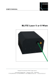
FB4 User Manual - BETA Pangolin Laser Systems Copyright 2015, Pangolin Laser Systems, Inc. All rights reserved. Due to our policy of continuous product improvement, information in this manual is subject to change without notice. Chapter 1 Getting Started Congratulations on selecting the FB4 Laser controller! You now own the most powerful and flexible lasershow controller hardware available for use with Pangolin software. FB4 gives you the exceptional laser quality and convenience, along with the ability to use both QuickShow and BEYOND software. Power If you purchased a laser projector that includes FB4, then power is already supplied from inside the projector. If you are a projector manufacturer incorporating FB4 into a projector, you will need to supply power to the FB4 at the connector shown on the left. The power required is a single +5 to +30 volts, at 2 watts. This may be sourced from the same power supply that feeds the scanners or laser diode drivers. The power connector is located at the top of the FB4 as shown. A stripped and tinned wire must be firmly pressed into each round hole found on the connector. With the FB4 in the orientation shown above, negative is on the left and positive is on the right. The connector will normally have red and black markings to indicate positive and negative, respectively. 4 FB4 User Manual If you need to remove the power wires from the FB4, each wire may be released by inserting a very small pin or tip of an X-ACTO knife into the small slots adjacent to each hole. Connecting to a Projector The FB4 has "Axis output" and "Color output" signals having a voltage level that is compatible with the ILDA-ISP standard. If your FB4 is not already installed on your projector, please refer to the Appendix A for the pinouts. Turning it on When power is applied to the FB4, a green light will illuminate. Pressing down on the knob will wake up the FB4 for configurations. FB4 is configured at the factory to be usable with Pangolin's QuickShow or BEYOND software. However, other operational modes are possible, including DMX, OSC, as well as the ability to access internal test patterns when they are stored on the removable SD memory card. Initial Operation Connect FB4 to your computer or local area network using a standard CAT5 or CAT6 Ethernet cable. When FB4 detects a network, the yellow light on FB4 should flash indicating network activity. From the factory, the FB4 is initially configured to use an automatic IP address, but FB4 may also be assigned to a manual IP address using the menus accessed using the dial on the front. Chapter 1 Getting Started 5 Software Setup Download and install QuickShow or BEYOND, which can be found on installation media included with FB4 (or included with the projector). You may also check the Support section of the Pangolin web site to ensure that you are using the very latest version of QuickShow or BEYOND. When you start the software, it should automatically detect the FB4 and show it on the status bar. Within the Projector Settings dialog box, use the test patterns to perform initial setup including size, scan rate and color adjustments. Appendix A FB4 Connections Note that this manual is currently evolving, and FB4 includes some features that are not yet documented. Power Input Connector The Power connector is located at the top as shown in the picture. A stripped and tinned wire must be firmly pressed into to the holes in the connector. To release a wire after it has been inserted, insert a small pin or the tip of an X-ACTO knife trough the small slits adjacent to each hole, and then pull on the wire. FB4 requires +5 to +30 volts DC, at 2 watts. If you use the optional DMX or ILDA daughterboards, 2.5 watts of power should be budgeted. Appendix A FB4 Connections Axis (X and Y scanner) Outputs Axis Output Pin Signal name Voltage level 1 2 3 4 5 6 Y Positive + Y Negative GND GND X Negative X Positive + -5V to +5V -5V to +5V -5V to +5V -5V to +5V 7 8 Lasershow Player model FB4 User Manual Color Outputs Color Output Pin Signal Name Voltage level 1 2 3 4 5 6 7 8 Color 1 (Red) Color 2 (Green) Color 3 (Blue) Color 4 (Deep Blue) Color 5 (Yellow) Color 6 (Cyan) Shutter GND 0 to +5V 0 to +5V 0 to +5V 0 to +5V 0 to +5V 0 to +5V 0 to +5V Appendix A FB4 Connections 9 ILDA DB-25 Pinouts If you want to connect FB4 Axis and Color outputs to an ILDA DB25 connector, the relevant signal names, pin numbers, and voltage levels are described below. Signal name X+ Y+ Intensity/Blanking + Interlock A Red+ Green+ Blue+ Deep blue + Yellow + Cyan + Z+ Not connected Shutter XYIntensity/Blanking Interlock B RedGreenBlueDeep blue Yellow Cyan ZGround Pin 1 2 3 4 5 6 7 8 9 10 11 12 13 14 15 16 17 18 19 20 21 22 23 24 25 Voltage level / Notes -5V to +5V -5V to +5V (not applicable to FB4) (connect to pin 17) 0V to +5V 0V to +5V 0V to +5V 0V to +5V 0V to +5V 0V to +5V (not applicable to FB4) 0V to +5V -5V to +5V -5V to +5V (not applicable to FB4) (connect to pin 4) (connect to pin 25) (connect to pin 25) (connect to pin 25) (connect to pin 25) (connect to pin 25) (connect to pin 25) (not applicable to FB4) Common ground / cable shield 10 Lasershow Player model FB4 User Manual Shutter Actuator Output Connector FB4 has a built-in PWM output which may be connected directly to an actuator, for the purposes of implementing a redundant mechanical shutter. The signals are described below. Shutter Actuator Output Pin Signal name 1 2 GND PWM Voltage Output As a shutter actuator, we recommend the VRAD 1510 or VRAD 506 actuator from the ScannerMAX division of Pangolin. Appendix A FB4 Connections 11 X-Y Scanner Position (feedback input) Connector FB4 can optionally monitor the X-Y scanner's position signals and provide additional safety-related functions. These functions are selectable and adjustable in the FB4 menus. When implemented, the scanner's position signals may be fed into the FB4 as described below. If this signal is not implemented, the connector should be left unplugged. Feedback Pin Signal name Voltage level 1 2 3 4 Y+ YXX+ -10 to +10 -10 to +10 -10 to +10 -10 to +10 12 Lasershow Player model FB4 User Manual FB4 ILDA Daughterboard Connector FB4 may be connected to an optional daughterboard which provides ILDA-Input and ILDA-Through capability. When this daugherboard is used, FB4 can direct the ILDA Input through FB4 circuitry for signal modification, before forwarding those signals to the Axis and Color outputs on the FB4. The signal modification includes the ability to adjust the color level and color shift as well as the orientation of the ILDA input. All of these ILDA input signal modifications are accessible through the FB4 menus. ISP Input Pin Signal name 1 2 3 4 5 6 7 8 9 10 11 12 GND I2C SDA I2C SCL I2C INT VCC (3.3V) B IN G IN R IN Y IN X IN VSS (-5.8V) VDD (5.8V) Appendix A FB4 Connections 13 FB4 DMX Daughterboard Connector FB4 may be connected to an optional daughterboard which provides DMX-Input and DMX-Through capability. When this daugherboard is used, FB4 can receive DMX signals and trigger content stored on the removable SD memory card, as well as adjust the size, position, rotation, color and other parameters. The DMX capability provided by this daughterboard also conforms to the RDM standard of DMX. The DMX and RDM functionality of the FB4 is accessible through the FB4 menus. RDM Pin Signal name 7 6 5 4 3 2 1 GND DMX RX DMX TL I2C SCL I2C SDA I2C INT VCC (3.3V) 14 Lasershow Player model FB4 User Manual Status Indicator Lights GREEN - Power & SD card status - OFF: No Power - FLASHING: Not used at the moment - BLINKING: No SD Card - SOLID ON: SD Card Present YELLOW - Network status - OFF: Network is not detected - FLASHING: Obtaining IP Address - BLINKING: IP Address Obtained - SOLID ON: Connected to QS or BEYOND ORANGE - DMX & Art NET status - OFF: No active DMX or Art NET signal detected - BLINKING: DMX signal detected - SOLID ON: ArtNET or sACN detected Appendix A FB4 Connections 15 RED - Laser Emission status - OFF: No laser output (and no connection to QS or BEYOND) - SLOW BLINKING: QS or BEYOND active, Laser output disabled - BLINKING: QS or BEYOND active and Laser output is enabled SPECIAL CASES: - ALL 4 LEDs BLINKING: Waiting for Firmware Update and No Valid Firmware on the SD Card - ALL 4 LEDs SOLID ON: Firmware Update in Progress Appendix B The following article appeared in the 2012 edition of The Laserist magazine. It is provided below as guide to connecting the FB4 with the other projector components. Making the right connections for a perfect image Incorrect connections can lead to distorted images and other problems, which are then mistakenly blamed on poor scanner tuning or poor component performance. Incorrect connections can also lead to a dangerous projector – for example, one which will output a beam even when it is not connected. This article is intended to be a guide for projector manufacturers on the best way to assemble components to create a laser projector conforming to the ILDA Standard Projector (ISP) specification. When discussing the connections inside a laser projector, it is best to conceptually separate these connections into two categories: Connections that are related to power supplies (referred to as “Power Connections”); and connections that are related to the ILDA DB-25 signals (referred to as “Signal Connections”). We will discuss the power connections first. Appendix B Making The Right Connections 17 Power Connections Figure 1 general manner in which power connections should be made between the various components. 18 FB4 User Manual We will discuss the connections for the scanner power supplies first, because they are at the top of the diagram, and also because once that foundation is laid, the other power connections can be easily understood. Power enters the projector from the AC Mains Supply. An integrated switch and fuse assembly is often used as shown. The international color standard specifies the brown wire as the LINE (or “Hot”) lead, and the blue wire as the NEUTRAL lead. These are connected to the power supply LINE and NEUTRAL connections respectively. If you look closely at the power supply, you should see the words “Line” and “Neutral”, or letters “L” and “N” that designate which wire goes where. Note that there are AC power cords that do not have polarized plugs, and these two may become swapped at the point that the projector plugs into the wall. However, you should still maintain a sense of “Line” and “Neutral” throughout the laser projector, always connecting the “Line” terminals of all power supplies to the same (preferably brown) wire, and “Neutral” terminals to the other (preferably blue) wire. The most important difference between the “Line” and “Neutral” connections, is that the “Line” connection is the one that you use when connecting a switch and fuse in line with power supplies. With laser projectors whose optical output power is relatively low (for example, a few hundred milliwatts) and projectors that have a plastic enclosure, there may only be two AC power wires (Line and Neutral) and the Ground wire may or may not be used. For projectors that have a metal enclosure, a Ground wire (international color code is green as shown) must always be used and connected as shown. The Power Connections diagram shows two separate power supplies used to generate +24V and –24V for the scanner amplifiers, but this could be embodied as a single power supply that generates both voltages as indicated by the light gray box. In either case, the +24V and –24V power wires are connected from these power supplies to the scanner amplifiers. As with the power supplies, the scanner amplifiers may also be embodied as two separate single-axis amplifiers, or as one dual-axis amplifier as indicated by the light gray box around them. The most important part of Figure 1 is the “Central Grounding Point”. This is really the single most important connections concept inside the laser projector, and the thing that many people do not initially Appendix B Making The Right Connections 19 understand. Basically, any component inside the laser projector that requires a ground connection should make a “home-run” to the “Central Grounding Point”. This connection scheme is called a “Single-Point Grounding Scheme” which is also known as a “Star Grounding Scheme”. The “Central Grounding Point” should be located close to the power supplies. Unlike the +24V and –24V, which can simply be connected to the scanner amplifiers in a daisy-chain fashion as shown, the ground connections (designated PG in the diagram for “Power Ground”) require more careful consideration, and must each make a “home run” type connection to the “Central Grounding Point”. When an AC ground connection is used (green wire on the diagram), the easiest thing to do would be to connect it to the “Central Grounding Point” as well. This is because, often times this “Central Grounding Point” is eventually (through “phantom ground connections”) connected to the optical plate within the projector. If “phantom ground connections” can be completely prevented, then the AC ground connection could simply be connected to the projector chassis, but not to the central grounding point. This provides the best performance, but requires the most careful projector design and layout, and close attention to detail in terms of avoiding “phantom ground” connections. When an AC ground is not used, or when the AC ground is connected only to the projector chassis and there are absolutely no “phantom ground connections” then ILDA DB-25 pin 25 MUST be connected to the “Central Grounding Point”. Note that the ILDA DB-25 pin 25 should NOT be connected to the “Central Grounding Point” if the AC ground connection is already connected there, otherwise there will be a ground loop formed external to the projector, which is undesirable. 20 FB4 User Manual Power Connections For the Laser In addition to showing the connections for the scanner power supply, Figure 1 also shows the connections for the lasers. However, unlike the connections for the scanner amplifiers, the connections shown for the lasers are intended to be more conceptual than literal. The reason is because, although scanner amplifiers are highly standardized and generally all require the same kind of power supplies and connections, the lasers themselves may have integrated AC power supplies and laser diode drivers, or may each operate on a separate power supply and driver. The diagram shows a single power supply operating three solid-state laser diode drivers, but there may be only a single laser, or in fact the laser may be an ion laser with completely separate power supply. Nevertheless, the diagram shows conceptually what must be accomplished for best results. If the laser power supply is small enough to fit within the projector, then the “Power Ground” from the power supply, as well as the “Power Ground” from the laser diode driver should each be routed to the “Central Grounding Point”. If an ion laser were used, then a PCAOM would be used to modulate the beam. In this case, you would connect the Power Supply of the PCAOM driver, as well as the PCAOM driver each to the “Central Grounding Point” using a “home-run” type connection. Projector Interlock (required by the ISP standard) Figure 1 also shows a relay placed in series with the laser power supplies. This relay is intended to facilitate the “interlock” feature of the ILDA Standard Projector. When connected as shown, the laser diode drivers (and optionally, the shutter driver) will only receive power when the interlock loop is closed. The interlock facilitates an additional layer of safety for laser projectors, and is required by the ISP standard. It is also possible for users to place a “Red Mushroom Switch” in series with the ILDA cable and connected to the interlock lines. This Appendix B Making The Right Connections 21 provides an easy mechanism for laser operators to prevent laser output when needed. The interlock portion of the ISP standard is intended to help prevent light from coming out of the projector if the projector is mistakenly connected to a non-laser signal source. Although it is shown in the diagram as a relay, which applies or removes power from reaching the laser diode drivers, the interlock system may be implemented in other ways, including as an additional shutter within the projector. The ISP specification allows for voltages up to 25 volts, and currents up to around 160 milliamps to exist on the DB-25 pins. Thus, the projector interlock must be facilitated in such a way that these values are not exceeded. However, I recommend that you try to implement an interlock that uses far less voltage and current – for example 5 volts and 5 milliamps. This could be done using an electronic relay instead of an electro-mechanical relay. The interlock signals may also be implemented using other methods that might provide an increased level of safety – for example, by outputting a small sine-wave signal on pin 4, and comparing it to the voltage received on pin 17. It is also a good idea to put an LED or some other indicator somewhere within the interlock system so that the user can see when the interlock is enabled or disabled. In the diagram, we show an LED connected as the Laser Emission Indicator. 22 FB4 User Manual Signal Connections Figure 4 We will now discuss the connections that are related to the ILDA DB25 signals, starting with a discussion of the scanner amplifiers. The ILDA DB-25 connector primarily contains signals that control the motion of the beam (i.e. X-Y scanning), and the color and brightness of the beam (i.e. R, G, B beam power). There are other signals on the DB-25, such as the projector interlock mentioned above, a shutter signal, and some multi-propose “user” signals, but this article only discusses motion and color related signals, as well as the shutter and projector interlock. Appendix B Making The Right Connections 23 The motion- and color-related signals are arranged as differential pairs. For the purpose of the laser projector, the word “differential” means that the laser projector must derive the actual signal level by taking the difference between two signals (i.e. by subtracting). For example, ILDA DB-25 pin 1 contains the X+ signal, and pin 14 contains the X- signal. Often times, when pin 1 is going from 0V to +5V, pin 14 will be going from 0V to –5V. The actual signal level is found by subtracting; thus +5V minus –5V = +10V. This means that the voltage level that the X scanner amp should sense is +10V. Note that I used the term “often times” above. The reality is that there is no strict requirement for the X- signal to be “equal but opposite” when compared to the X+ signal. As far as the projector is concerned, the same X position could be commanded if the X+ signal goes to +10V and the X- signal stays at 0V, because +10V minus 0V = +10V. Likewise, the same result could be generated if the X+ signal goes to +20V and the X- signal goes to +10V, because +20V minus +10V = +10V. This is an important concept, because the ISP standard absolutely requires projectors to derive all motion and color signals by taking the difference between two signals. No motion or color signal should be assumed to be referenced to ground, and – within the projector – no motion or color signal should be connected to ground. With that in mind, you will notice that we connect ILDA DB25 pin 1 to the X+ input on the X scanner amplifier, and we connect pin 14 to the X- input. For the Y axis, we connect pin 2 to the Y+ input of the Y scanner amplifier, and we connect pin 15 to the Y- input. Note that, although the scanner amplifiers themselves may have a “Signal Ground” input (labeled SG in the diagram), this is NOT connected!! The reason this is not connected is because if it were, this would destroy the single-point grounding scheme that was established and discussed above in the Power Connections section of this article. Basically, since the scanner amplifiers have differential inputs, it is only those differential inputs that are used for ILDA DB-25 signals. The only ground connection is made from the “Power Ground” to the “Central Grounding Point” already mentioned above. If a scan-fail interlock were used, it would be connected to the X POSITION and Y POSITION signal from the scanner amplifier. But, there is something tricky to watch out for. You should consult the 24 FB4 User Manual manufacturer of the scan-fail interlock to determine whether or not the scan-fail interlock itself has a differential position input. If the scanfail monitor does not have a differential position input, you should NOT connect the “Signal ground” or “Position ground” from the scanner amplifier to the scan-fail monitor. Doing so would, again, destroy the single-point grounding scheme. The scan-fail monitor already has a ground connection to the “Central Grounding Point” established on the Power Connections diagram. You should only connect the scan-fail monitor to the scanner amplifier’s ground connection if the scan-fail monitor itself has differential inputs. Pangolin’s PASS safety system does have a differential position input, but most others do not. The scan-fail monitor would also be connected to a shutter or to the laser diode drivers, but the method of connection depends on the exact scan-fail monitor being used. Consult the manufacturer of the scanfail monitor for details. The color signals are connected in exactly the same way as the X and Y signals were connected, using differential signaling. ILDA DB-25 pin 5 is connected to the “positive modulation input” on the red laser diode driver, while pin 18 is connected to the “negative modulation input”. ILDA DB-25 pin 6 is connected to the “positive modulation input” on the green laser diode driver, while pin 19 is connected to the “negative modulation input”. ILDA DB-25 pin 7 is connected to the “positive modulation input” on the blue laser diode driver, while pin 20 is connected to the “negative modulation input”. The discussion about color signals above, as well as the diagram makes the assumption that the laser diode driver has differential inputs to begin with. As two examples, laser diode drivers made by Laserwave and by Viasho do have differential inputs, but, as two other examples, laser diode drivers made by CNI and Melles Griot do not. Also, it is possible that the laser projector would have an ion laser and PCAOM used for color modulation. In this case, the same connection scheme and discussion applies. PCAOM drivers made by NEOS do have differential inputs, but PCAOM drivers made by AA do not. (In general scanner amplifiers to have a differential input, however some very low cost scanner amplifiers may not.) Since the ISP standard absolutely requires all motion and color signals to be implemented as differential pairs within the projector, this means that if you have scanner amplifiers or laser diode drivers that do not have differential inputs, you will need to implement the differential receiver as a separate circuit. Appendix B Making The Right Connections 25 One easy way to do this is with a difference amplifier, as shown in Figure 5, below. A single op-amp along with four resistors can be used to receive the differential signal from the X, Y, R, G, or B signal, and generate a “single ended” signal which is then connected to the scanner amplifier or laser diode driver. Note that this circuit is drawn and implemented in such a way that it has two inputs and also two outputs. One of the outputs is the “single-ended” signal that drives the component, but the other output is a “ground reference”. This needs to be connected to the “Signal ground” input terminal of the scanner amplifier or laser diode driver. The connection is made this way in lieu of connecting this to any other ground, so that “Ground Bounce” can be detected and rejected by this circuit. Also note that this diagram does not show the pin numbers of the op-amp, and also omits the op-amp power supply connections for clarity. The op-amp must receive power from a power supply that is capable of feeding it a minimum of +5V and –5V. Figure 5, Difference Amplifier TTL Versus Analog Color Modulation (Avoiding Fires) The ISP standard requires the color signals to respond in an analog fashion, such that 0V does not produce any light from the projector, 2.5V produces around half the nominal laser power, and 5V produces the full laser power. The ISP standard also assumes that if the laser 26 FB4 User Manual projector is disconnected from the signal source, there should be NO light coming out of the laser projector (because there would be no difference between the differential color signals). I have recently seen several projectors that used laser diode drivers that used TTL modulation inputs rather than analog modulation inputs. TTL modulation basically means that the laser can be fully on, or fully off. This does not conform to the ISP standard. However, what’s worse is that the TTL modulation inputs “float high”, which means that when the projector is disconnected from the signal source, it produces a full-power, non-moving beam. On a recent trip, I saw this happen on two separate occasions, by projectors made by two separate companies. And in both cases, the non-moving fullpower beam landed on dark fabric, which actually caught fire!! One thing to keep in mind: under very bad circumstances, laser projectors may present hazards. Projectors must be designed to be safe, and one of the safety aspects is to prevent light from coming out of them when the projector interlock is opened, and when they are not connected. TTL modulation should really be avoided, but if it is used, at the very least, a differential receiver should be used which would force the TTL lasers to “float low” instead of “float high”. Shutter and DB-25 Common Signals The ILDA DB-25 pin 13 provides a signal to control a shutter, but its presence is somewhat optional, and may depend on local or federal laws where the laser projector is to be used. For example, for projectors that use solid-state lasers, it might be argued that between the fast and complete extinction offered by the laser diode driver itself, coupled with the fact that the projector interlock actually removes the power from the laser diode drivers, a shutter is therefore not needed. But for ion lasers, even those modulated by a PCAOM, a shutter would still be desired. In general, it can be said that the shutter Appendix B Making The Right Connections 27 offers an additional layer of safety for the laser projector, and thus it is a desirable thing to have. Unlike the motion control signals, and color control signals, the shutter signal is not considered to be an “analog” signal. It is TTL in nature, and thus, the shutter is either fully opened, or fully closed. The shutter is fully opened when pin 13 is roughly 5V when compared to pin 25. Also, the shutter signal is not a true differential signal, since noise immunity is not really needed, due to the fact that it is TTL in nature. However, for the purpose of projector connections, it should be considered to be a differential signal whose counterpart is pin 25. ILDA DB25 pin 25 is considered to be the “Common” signal of the ILDA connector. However, this “Common” signal is not necessarily a “Ground” signal, since, under many circumstances, this signal is not connected to “Ground” within the projector. Since the shutter signal is TTL in nature, and referenced to DB-25 pin 25, one good way to receive this signal is using an optical isolator. The optical isolator will receive the TTL-level signal between pin 13 and pin 25 and allow isolation of these signals from the rest of the projector components. DB-25 Connectors For projectors, the ISP specification states that the DB-25 connector should be a male connector. However, I recommend putting two connectors on the projector – one male, and one female. This maximizes ease-of-use because it allows the use of any type of DB-25 cable between the projector and signal source, and also allows easy daisy-chaining of multiple projectors when needed. 28 FB4 User Manual Beware of the Phantom Ground Connections Above we have discussed the benefits of using a single-point grounding scheme. One thing to be aware of is that even when the wire-connections are made carefully, it is possible that the components themselves might provide phantom connections to ground, thus destroying the single-point grounding scheme and creating more of a spider-web-shaped grounding scheme. For example, this would happen if the metal housing of a DPSS laser is connected to the laser diode driver’s ground connection. A phantom ground connection would be made by screwing the metal DPSS laser housing down to the metal base-plate in the laser projector. Therefore, when assembling the laser projector, you will need to use an ohmmeter, to identify which components have metal parts connected to the electrical ground, and which might come in contact with the baseplate, or other conductive projector parts. Once such parts have been identified, they should be isolated from the projector base-plate. I always recommend using nylon spacers under any laser, to provide a physical and electrical separation between the laser and the base-plate. The metal case of scanners, and thus, the X-Y mount of the scanners are another notorious place to generate a phantom ground connection, and this should be isolated where possible. Other Projector Parts That May Be Necessary In addition to the fundamental components described above which are certainly a part of most laser projectors, additional components might also be needed or desired. For example, the United States and certain other countries require additional safety features for laser projectors, including “laser emission indicator”, “key-switch”, “cover interlock”, “external interlock”, “time delay” and a “manual reset”. The laser emission indicator was described above. The other elements are described below. Appendix B Making The Right Connections 29 A key-switch is required for laser projectors because, under the wrong circumstances, laser projectors could be hazardous, and should be used only by trained laser operators. To prevent untrained personnel from operating the laser, a key-switch is used. The key should only be given to the trained laser operator. If the projector covers could be easily opened or removed by a user or operator, the laser projector is required to have a cover interlock, which will prevent the lasers from operating when the cover is opened. This cover interlock is ideally implemented as two spring-loaded switches connected in series with the general projector interlock loop described above. Two switches are used instead of one, to provide redundancy in this safety feature. Some governments may require an additional connector to be placed on the projector called an external interlock connector. Electrically, this connector only needs to have two pins, and this is connected in series with the general projector interlock loop. One example of how this connector might be used is when the laser projector is only supposed to project a certain effect (such as a cone shape), at only a certain time (such as, when a performer is in just the right place that the cone will surround them). The external interlock can be connected to a “pressure pad” that is only active when the performer is standing in place. A time delay is used so that, when the projector is turned on, it won’t start emitting laser light right away. This is in place so that the laser operator can turn on the laser projector, and then advise others who might be in the room that the laser is coming on. The time delay allows the laser operator and others to take their place to avoid accidental exposure to the laser. Of course, this assumes that exposure would be harmful in the first place, which isn’t always the case. Nevertheless, the US and other countries require a time delay to be a part of the projector. The time delay is normally set for 20 to 30 seconds. A manual reset is required so that if power is interrupted from the laser projector, and then power is restored at some point in the future, the laser projector will not automatically start outputting light until some manual intervention takes place (such as pressing a button, or cycling the position of the key-switch). The manual reset provides an additional level of safety. Consider this scenario: a laser projector is operating in a nightclub, but at some point, the power to the entire night club goes out. Then everybody leaves because there is no power. Some time later the power comes back on. If the laser also comes back on and emits a non-moving beam, and if this non-moving beam is parked onto dark fabric, it could start a fire. Because of factors such as this, the manual reset is required by certain countries. The key-switch, cover interlock and external interlock are all easily 30 FB4 User Manual understood and implemented, but the time delay and manual reset provide some difficulty since off-the-shelf components such as laser diode drivers do not have a time delay or manual reset feature. Often times these two features are implemented in the form of an electronic circuit made by the projector manufacturer. As a point of interest, Pangolin’s Professional Audience Safety System (PASS) incorporates differential receivers for both the color signals and position signals, and also implements the time delay and manual reset features, thus, this multi-purpose projector control board can help to solve some of the most difficult problems in constructing a projector. Appendix C FB4 Engineering Drawings FB4 User Manual Appendix C FB4 Engineering Drawings 33 FB4 User Manual Appendix C FB4 Engineering Drawings 35