1
C o m ~ u t i n g 31, 317 - 346 (1983)
~
~
9 by Springer-Verlag1983
Softwa~ Specification Using Graph Grammars
G..Engels, R. Gall, M . N a g l , a n d W . S c h i i f e r , O s n a b r i i c k a n d E r l a n g e n
Received April 18, 1983
Abstract - - Zusammelffassung
Software Specification UsingG~aph~Grammars. The following paper,demonstrates :fhat :programmed
sequential graph grammars canbe used in a systematic proceeding tospecify tbechanges of highilevel
intermediate data structures arising in aCpFogrammingsupport environment, in which all tools,work in
an incremental and syntax-tlrivenmode. In this paper we lay stress upon the way to get the specification
rather than on the result,0f this:process. Therefore, we give here some approach to "specification
engineering" using graph grammars. This approach is influenced by the syntactical definition of the
underlying language for Programming in the Small, the module concept etc. to be supported on one side
but also by the idea of,the user interface.
AME'Szibject Classifications: 68 B 05, 68 B 10,68 F 05, 6"8!F25, 90-04.
:Key.wards: Software development environments, software specification, syntax, graph grammars.
Speziftkaiion von Software mittels Graph-Grammatiken. Der folgende.Aufsatz zeigt auf, dab program~mierte sequentielle Graph-Grammatiken ,dazu benumt werden krnnen, die Ver~inderung ~hoher
..Zwischeneodeszu spezifizieren, die im Kontext einer Software-Entwi~k,tungsumgehung auftreten, deren
~W_e~kzeugealle inkmmentell und syntaxgesteuert arbeiten. Wir legen in diesem Atffsatz mehr Wert ~tuf
,die ~Brl/iuterung.einer systematischen Vorgehensweise, um die Spezifikation zu erhalten, als auf die
detaiUierte Ab~handlungder Spezifikation selbst. Somit kann diesesPapier'auch als ein Ansatz zu einem
,;Spezifikations-Engineering" mit Hilfe von Graph-Grammatiken angesehen werden. Der Ansatz wird
maBgeblich beeinfluBt won der Syntaxdefinition der zugrundeliegenden formalen Sprache for das
Pro grammieten im ~Kleinen bzw. fiir das Modulkonzept etc. einerseits und andererseits vonder
Worstellung der tForm, iier Benutzerschnittstelle.
1. I n t r o d u c t i o n
T h e software w h i c h is to he specified b y g r a p h g r a m m a r s i n the following p a p e r is a
programming support :environment ,(other n a m e s : software d e v e l o p m e n t system,
p r o g r a m m e r ' s w o r k b e n c h , etc.'), i,e. a set of tools i m p l e m e n t e d b y software which
~themselves facilitate ~he d e v e l o p m e n t , o f software. T h e user of such an e n v i r o n m e n t
usually is a ! p r o g r a m m e r . [ B u 80a] s u m m a r i z e s the r e q u i r e m e n t s of a n (in this case
Classic) enx/ironment, ~ta~lored :for :the p r o g r a m m i n g l a n g u a g e Ada. T h e i d e a of such
e n v i r o n m e n t s i s ( l ) to e a s e soft,ware p r o d u c t i o n , (2) to i m p r o v e t h e reliability a n d
efficiency of ~software, a n d t h e r e b y (3) m i n i m i z i n g the o v e r a l l ~osts 'for software
within the w h o l e software life ,cycle ( p r o b l e m analysis, design, iimplementafion,
v a l i d a t i o n a n d evaluation, integration, installation, maintenance).
318
G. Engels, R. Gall, M. Nagl, and W. Schiller:
The aim of the project I P S E N (Incremental Programming Support Environment)
which is carried out at the University of Osnabriick in cooperation with other
universities is to develop and implement such an environment. Within IPSEN all
"technical" activities of software development are investigated, which means that
support begins when the design has started, i.e. a part of the specification has been
worked out.
IPSEN has the following characteristics:
9 Incremental mode: The input is given in terms of language portions (increments)
rather than by arbitrary text strings. Analysis, evaluation, or execution is even
possible for partial programs, specifications, etc. This avoids a correction cycle
which e.g. for programs consists of reediting, recompiling, relinking before
execution after a change.
9 Syntax-directed: Any input is immediately checked, corresponding to context
free as well as context sensitive relations and, consequently, incorrect inputs are
rejected. Also, all implications of the input or the change of an increment are
displayed. Therefore, a (partial) program or specification can never be syntactically incorrect. The admissible alternatives for increment inputs or changes are
indicated to the programmer by menus or help information.
Command-driven: The user specifies by a command what he wants to do rather
than only putting in the corresponding text string. Therefore, the system knows
the user's intention which eases the analysis for syntactical correctness. On the
other hand, parts of the concrete syntax as word symbols and delimiters can be
generated automatically by the system.
High-level intermediate data structures: Incremental mode enforces that all
information contained in an external representation of a program, specification,
etc. iscontained in and can be accessed from an intermediate data structure. On
the other hand, support of program development especially means that messages
corresponding to syntactical or semantical errors, or reporting on some kind of
evaluation or execution are given in terms of constructs of the corresponding
programming language, specification language etc. and not in those of internal
characteristics of the underlying machine. These intermediate data structures are
regarded to be graph-like here. Therefore, we call the intermediate code of a
program system the system graph, that of a single program module the module
graph, and so on. These graphs are the centers of all activities corresponding to
system changes, module changes, etc.
9 Uniform user interface: The user interface for all tools is styled uniformly. Thus
the user has not to realize the change of an activity from one tool to another.
IPSEN is implemented on a remote mini-computer, which, together with all
tools, results in a proorammin 9 support machine.
Adaptable: Of course, the chosen module concept or programming language to
be supported heavily influences the concept of a software development environment. As a consequence, one major goal of designing a programming support
environment like IPSEN is to get adaptability to other module concepts as well
as to other programming languages.
Software Specification Using Graph Grammars
319
9 Integrated concept: Here, integrated means: (1) that most of the activities arising
in the software life cycle are supported, (2) that the user interface is uniformly
styled (as mentioned above), and (3) that tools are offered which combine related
activities which are regarded to belong to different phases of software development in classic environments.
Because of the incremental mode of the environment there is no sequential division
of software development activities as suggested by the terms of software life cycle
models. For example, the distinction between design, integration, and maintenance
of a software system can no longer be sustained. At the time a part of the
specification of the software system is put into the system, the (partial) integration
can start (check for consistency of intermodular connections) and at the same
moment the maintenance can begin (e.g. changes due to variations of the
requirement definition). Corresponding to this view we have grouped the activities
within software development when using an environment like IPSEN into the
following three main problem areas:
9 ProgrammingintheLarge(containingthedesignofthesoftwaresystemusingany
specification language, transformation into an implementation language, integration maintenance of the software system etc.).
9 Programmin 9 in the Small (module design, module coding, validation, module
maintenance).
9 Organizational ltems (project management, project organization, variant/version control, release control, support of documentation, etc.).
Of course, these three problem areas cannot be strictly separated. For example, one
result of Programming in the Large can be a skeleton for each module, where the
interface (export, import) of the module is fixed. On the other hand, within
Programming in the Small a module can only use those resources, which are
imported, and, conversely, all resources have to be realized, which are exported. So,
also these problem areas are interleaved. Moreover, integrated tools, as mentioned
above, cannot be designed and implemented without having managed an interaction
between the various graph-like data structures. If, for example, one implements a tool
handling all the tasks which have to be carried out when the export of a module is
changed, then this tool must control activities corresponding to (1) project
management (as not everybody is allowed to do this change), to (2) project
organization (as the cost of this change should be estimated), to (3) release control (as
this module now is no longer accessible), to (4) variant/version control (as the old
system which contained the module may further exist as a special variant), to (5)
specification within Programming in the Large (as all implications of this change
have to be found out and corresponding changes, namely within the corresponding
import clauses, have to be carried out), to (6) Programming in the Small (as the new
import also leads to changes within the module implementation), to (7) documentation (as the technical documentation has to be altered also) etc.
In this paper we mainly deal with Programming in the Small and only to a certain
extent with Programming in the Large. Furthermore, all aspects of evaluating and
executing (partial) program modules or (partial) program systems are not regarded
here. So, we concentrate exclusively on syntactical aspects here (including the
21 Computing 31/4
320
G. Engels, R. Gall, M. Nagl, and W. Sch/ifer:
context sensitive syntax). The topic to be considered in detail is, which kind of
incremental syntax-aided editing in a broad sense is possible and reasonable within
Programming in the Small and Programming in the Large.
For high level intermediate data structures we use graphs rather than trees (together
with attributes). The reason is that (1) graphs are a uniform model which can be
applied to internal high level intermediate codes of all problem areas, (2) there is no
(artificial) distinction between the information which can be expressed within trees
or outside trees, and (3) also aspects of evaluation and execution of program modules
and program systems can be treated by the same model, as further information for
evaluation and execution purposes can be integrated without leaving the class of
admissible intermediate data structures. This, however, is not a reasoning for
avoiding attributes at all. Attributes are necessary for expressing values. We pledge
for using the same model for all structural information.
In order to describe how modules and programming systems are built up and
changed, we use graph grammars as a specification instrument. This specification is
given for the graph-like intermediate data structures. Here, specification has a twofold meaning: on one side we make clear how these incremental changes on the
module or system graph look like, therefore using the term specification in the sense
of making things precise on some more abstract level. On the other hand, we will
show that this specification is also a specification in the software engineering sense,
i.e. that it yields a detailed guide how to write the software realizing IPSEN. This
graph grammar specification uses sequential programmed graph grammars. Here,
sequential means that one rewriting step takes place after the other, programmed
that such a rewriting step internally consists of a sequence of applications of
productions where so-called control procedures determine the order of applications.
In this paper no formal details about graph grammars in general and sequential
programmed graph grammars in particular are given. The reader is referred to
[Na 79].
This paper is based on [Na 80] where the concept of an integrated programming
support environment is sketched originating from an incremental compiler. Other
approaches for programming support environments started from different points of
view, as G A N D A L F [Ha82], M E N T O R [ D G 8 0 ] , the Program Synthesizer
[-TR 81]. Rather independent from each other they all developed similar integrated
concepts. However, regarding graphs and not trees as internal structures and using
graph grammars as specification instrument is specific to IPSEN. Parts of the
presentation of this paper can be found in more detail in [ES 82] and [-GA 82, 83]
and a preliminary version of this paper is given in I-NEGS 83]. A forthcoming paper
will discuss the overall concept of IPSEN.
The organization of this paper is as follows: Most of the paper, namely sections
2 - 8, deal with the problem area Programming in the Small, which is presented in
detail. For that, the input mode of syntax-aided editing is given first which later is
generalized to cover the full incremental mode, where inputs, changes, and deletions
may be done in any order. We start with comments on the user interface in section 2,
then in section 3 we make precise on the string level what we mean by an increment
and which kinds of increments we need for further proceeding. In section 4 we give
Software Specification Using Graph Grammars
321
guidelines how to modify the grammar of the underlying programming language in
order to get these kinds of increments. In section 5 the increments are discussed onthe graph level and the overall structure of the module graph is presented.
Furthermore, in section 6 we construct the programmed graph grammar for the
input editing mode. In section 7 and 8 the user interface and the programmed graph
grammars are revised to handle the full incremental mode. Finally, section 9 outlines
that an analogous proceeding can be applied for the problem area Programming in
the Large.
2. Sketch of the User Interface
Before starting with incremental editing, it is useful to sketch the state o f the art how
a program nowadays is put into a computer. In most cases the source code of a
module is edited by a usual text editor irrespective that it has to be written in some
formal notation and it is not arbitrary prose. Then it has to be analyzed syntactically
(usually as a part of compilation). After some syntactical corrections the module is
syntactically correct. Changing this module means to start again with text editing
and reanalyzing the complete source. This proceeding is inefficient because of two
reasons: (1) it takes a long time to know about syntactical errors, and (2) it is
inconvenient to force the programmer to learn unimportant details of his
programming language as e.g. the word symbols and delimiters of the concrete
syntax.
As the idea of the user interface of our syntax-aided editing tool has a deep influence
on the graph grammar specification we start our discussion by sketching the user
interface in this section.
We suggest a division of the screen into three different areas: (1) the working area
contains a part of the source code of a module in Programming in the Small, a
portion of the specification in Programming in the Large, some fragments of
documentation, when supporting the editing of user or technical documents, etc., (2)
the command area contains menus for command selection, text fields for parameters
corresponding to selected commands etc., and (3) the status line reports on the tool
which is used, the expected reaction time etc. The latter is no longer regarded in this
paper. Working area and command area contain two different cursors indicating the
actual position. These are called working cursor and command cursor in the following
text.
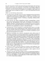
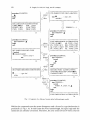
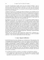
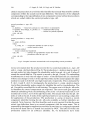
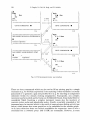
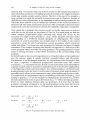
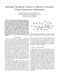
Let us regard a f r a g m e n t o f a session within which a PASCAL procedure with name
E X A M P L E is put in by making use of syntax-aided editing (cf. Fig. 1). We assume
that the skeleton of this procedure is already displayed in the working area. The
working cursor always points to the position where the source code is to be modified.
In our case (cf. Fig. 1. a) this cursor is located after the procedure head. Within the
command area a menu is displayed showing all possible inputs of the user, i. e. in this
case all possible declaration alternatives. Now, the user selects the third alternative,
namely ITD for insert type declaration.
21"
322
G. Engels, R. Gall, M. Nagl, and W. Schiifer:
I
procedure EXAMPLE;
9
begin
end;
( ~ j ] ITD INSERT TYPE DECLARATION
choice I
/ /
] typeB. . . . . . . . . .
type_def;
/~/ITD
I
identifier
k * * * * * * * * * * * * * * * * * * * * * * * * * * * * * * * * * * *1.* b
***********************************
DECLARATION ALTERNATIVES
LABEL mILD
VAR []IVD
CONST [] ICD
FUNC [] IFD
TYPE []ITD
PROC []IPD
************************************
1. a
procedure EXAMPLE;
type PERSON = 9
begin
end;
PERSON
procedure EXAMPLE;
type PERSON = 9
begin
end;
choice
IRT
IRT INSERT RECORD TYPE
[] packed
9 unpacked record
record_co 9 1
end
;
TYPE DEFINITION ALTERNATIVES
TYPE_ID l i T
AR_TYPE []IAT
EN_TYPE [] IET REC_TYPE[] IRT
SR TYPE 9
SET_TYPE DIST
PT_TYPE DIPT
FIL_TYPE D I F T
1.c
]\choice
] unI packed
*************************************
A
procedure EXAMPLE;
type PERSON =
record
end;
/ ~ ] begin
choice
end;
***********************************
/ / //
#I ***********************************
IRC INSERT RECORD COMPONENT / @ R C ] RECORD PART ALTERNATIVES
J
I
I c/
[ ANOTHER RECORD COMP. 9
I ~ . . . . . . . . : type_def
[
/ VARIANT PART
[]IVP
id-list
I~
\ ************** ** ********* **********
/**************************************
l e
"
l.f
FIRST_N /
}------)
procedure EXAMPLE;
LAST_N
type PERSON =
break
record
FIRST N, LAST_N: 9
end;
begin
end;
TYPE DEFINITION ALTERNATIVES
l.g
Fig. 1. Fragment of a dialog of syntax-aided editing (input mode)
W i t h i n t h e c o m m a n d a r e a t h e m e n u d i s a p p e a r s a n d a f r a m e for t y p e d e c l a r a t i o n is
p r e s e n t e d (cf. Fig. 1. b). I n this f r a m e the w o r d s y m b o l type, the e q u a l sign a n d the
s e m i c o l o n are a l r e a d y c o n t a i n e d . T h e r e f o r e , t h e user n e e d n o t k n o w t h e s e c o n c r e t e
Software SpecificationUsing Graph Grammars
323
syntax symbols. The command cursor is at the position of the type identifier. Dot
sequences indicate all input fields within a frame and comments make clear, which
kind of input is allowed. Now, let us assume that the user types in the string
P E R S O N for the type identifier and then presses a special button "next" indicated
by a right arrow. As there is only one input field in this frame, the frame is already
completed (but, of course, not the type declaration increment).
The frame, which can be regarded as some cutout of the source code (enriched with
detailed information), is now transferred to the working area (cf. Fig. 1. c). The
working cursor now is at the position of a type definition. The command area
immediately shows all possible alternatives. We assume that the user chooses the
alternative for a record type definition.
In this case, the frame consists of the pair of word symbols record and end (cf.
Fig. 1. d). Especially, it contains no input field. However, by a selection the user has
to choose, whether the type definition is that of a packed record type or not. Now the
user may have chosen an unpacked type definition. Within the next menu (cf.
Fig. 1. e) the user is asked whether he wants to put in a record component and
elongate the list of components or whether he wants to switch to the optional variant
part. Let us assume that he decides for the first alternative.
Within the command area the frame for a single record component or a sequence of
components of the same type is displayed (cf. Fig. 1. f) which contains only one input
field for a list of identifiers. Now, the user types in the string FIRST_ N, then presses
the next-button by which the separating comma symbol is automatically generated,
then types in the string LAST_ N, and then, by pressing a break-button, indicates
that the list of identifiers for record components is completed.
Then, the frame is transferred into the working area (cf. Fig. 1. g) the working cursor
being at the position of a type definition. Thus, the displayed menu is the same as in
Fig. 1. c. Now, the user selects one alternative for type definition and the dialog may
proceed anyhow.
What can we learn from the example dialog of Fig. 1? The input of a language
increment is started by naming an insert command for this increment, which here is
done by selection from a menu. Increments may either be "simple", as a type
identifier, a record component name etc., or they may be "complex", as a type
declaration or a type definition. Complex increments are related to structured
frames. These frames contain comments to indicate input fields for simple
increments and to give hints what kind of input is expected. All possible symbols of
the concrete syntax are generated. Therefore, the user is liberated from learning
most of the concrete syntax of the underlying programming language.
The complete syntax of any input is immediately checked: This means (1) that it is
immediately checked whether an increment is possible in a special location at all, (2)
that the context free syntax rules of the increment (e.g. whether an identifier at a
certain place of an increment is correctly built up) as well as (3) the context sensitive
syntax rules corresponding to this increment (e. g. whether a record type declaration
does not contain two components with the same name, or whether a variable which
is used is also declared) are fulfilled. Therefore, no syntactically incorrect (fragment
of a) module source is possible (corresponding to the inputs which have already been
made).
324
G. Engels, R. Gall, M. Nagl, and W. Schfifer:
3. String Increments
Above we spoke of increments as the portions in which module source text is put in.
Of course, these increments are not arbitrary pieces of source text. Instead, they
correspond to language constructs or meaningful fractions thereof, as an expression,
an array type declaration, a while-statement etc. To say it in another way, they
correspond to the nonterminal symbols of the context free grammar of the
underlying programming language. A strin9 increment is any phrase derivable by
this string grammar which starts with the corresponding nonterminal symbol as
string axiom.
We distinguish between simple and complex increments. Corresponding to the
mode of input simple increments are not further divided. Instead, they are put in in
one step as a text string. In IPSEN simple increments are e.g. identifiers, literals, but
also arbitrary expressions. Therefore, there is a cut within the set of nonterminal
symbols of the grammar distinguishing between simple and nonsimple ones. (This
cut makes only sense for statement-oriented languages.) The reason for regarding
expressions as simple increments is that a division of expressions by commands into
subexpressions etc. until one ends up at the level of primitive operands is too
inconvenient. Whereas there may be a different opinion whether to make
expressions simple or not, identifiers, literals etc. must be simple as it is completely
up to the user to determine the identifier for an object, or the literal corresponding to
a compile-time value. Putting in the text string for a simple increment internally
leads to a complete syntactical analysis of this text string, which can be regarded as a
construction of a complete derivation subtree.
Complex increments on the other side are structured corresponding to the mode of
input by the IPSEN user. Their inpu t is started with a choice within a menu, i.e. by
the selection of a command. They usually consist of concrete syntax symbols as word
symbols or delimiters, and of simple increments and further complex increments.
Examples are a type declaration or a for-statement. As already sketched above the
user need not know the concrete syntax symbols (they are generated) nor the order of
simple or complex increments within a complex increment (they are displayed
within frames). Complex increments are derived step by step corresponding to the
user's input of choices and of simple increments.
Nonterminal symbols for simple or complex increments occurring within increments are called gaps. These gaps have to be filled by further activities of the user.
An increment is called not expanded or empty if besides concrete syntax symbols it
contains only gaps and no other increments. So, "boolean_expression" or "if
boolean_expression then statement" are empty increments. On the other hand an
increment is called totally expanded or full if it contains no gaps, neither for simple
nor for complex increments. Within all intermediate steps the increment is called
parHally expanded.
It is clear from the above discussion of different input modes that a complex
increment can either be empty, partially expanded, or full whereas a simple
increment can only be either empty or full.
For the input mode of text editing which we have sketched in the last section the
following situation holds: An increment is entered as an empty increment and it is
Software SpecificationUsing Graph Grammars
325
left as a full increment. Therefore, when having decided to put in a certain language
construct into the source code, this language construct is riot left until being
completed. This is not true for the full incremental mode which we regard later on.
An increment can be a part of another increment. Then we call it an inner increment.
An inner increment may be simple or complex. Nesting of data or control structures
is a consequence of complex increments being inner increments of complex
increments.
Increments are also classified whether they are optional or obligatory. There exist
optional simple increments (as e.g. the label of a statement) as well as optional
complex increments (as e.g. a type declaration). Analogously, we have obligatory
simple increments (as e.g. the boolean expression within an if-statement) as well as
obligatory complex increments (as the main program). Please note that corresponding to input optional complex increments always have a corresponding frame
whereas optional simple increments are always a part of the frame to a complex
increment.
In input mode frames always correspond to complex increments as outlined in the
last section. However, frames and complex increments are not the same. Especially,
inner complex increments B_i of a complex increment A are not contained in the
frame to A. The reason is that a complex increment may lead to an arbitrary
complex piece of source code which cannot be displayed in a region of fixed size on
the screen, i.e. here within the command area. If a complex increment contains
further complex increments, then these complex increments also have frames. So, a
frame is the "result" of a complex increment after erasing complex inner increments,
indicating simple increments or lists thereof as input fields and enriching this with
comments and giving it a certain layout.
In full mode simple increments also have frames which, however, only consist of an
input field. In input mode simple increments always occur as input fields within
frames of complex increments.
For any simple or complex increment there is a strin9 representation in the working
area on the screen as part of the source code. Here, also, nonterminal symbols are
not displayed. Furthermore, indentation and splitting of the increment to fit into
consecutive lines are characteristics of this mapping.
Nonterminal symbols of the grammar which do not belong to simple increments
need not always correspond to complex increments. Such nonterminal symbols may
also represent a choice out of a finite set of alternatives. Thus, these nonterminal
symbols represent a class of (here in most cases complex increment) nonterminal
symbols which are admissible in a certain place of source text. This is e.g. the case for
the nonterminal type which represents the nonterminal type identifier up to record
type. Of course, such nonterminals correspond to menus on the screen where one of
the members of the class has to be selected (cf. Fig. 1. c).
However, menus also correspond to situations where the user specifies whether he
wants to have an optional increment or not or whether he wants to have options out
of a determined sequence of options. The first is the case for the variant part selection
in Fig. 1. e, the second for the declarations in Fig. 1. a as the PASCAL syntax fixes
326
G. Engels, R. Gall, M. Nagl, and W. Sch/ifer:
the order of declarations. Finally, menus may also represent whether a cycle of
inputs of a certain kind of increments is continued or not. This e.g. is the case for the
first alternative of the menu of Fig. 1.e but also e.g. for the menu for statement
alternatives which after the input of a statement is presented again to determine the
kind of the next statement.
Complex increments may contain gaps which are filled by a list of elements of one
and only one class of nonterminals. This is the case for the components of a record or
the statements of a procedure body. As the user has to decide about the length of
such a list, each element of this list is always regarded as a separate simple or
complex increment, respectively. In the case of a complex increment there exists a
corresponding frame, while in the case of a simple increment in input mode the
whole list is contained within the corresponding frame.
Summing up we see that we have got three kinds of nonterminal symbols which are
differently represented in the command area: (1) simple increment nonterminals
which are represented as input fields within frames (nonterminal symbols which
correspond to parts of simple increments as e. g. factor, primary etc. do not appear at
the user interface and, therefore, are not interesting for our investigation), (2)
complex increment nonterminals which correspond to frames consisting of concrete
syntax symbols, input fields, and comments, and, finally, (3) menu nonterminals
which correspond to menus where one of more alternatives, an option, a sequence of
options, or the continuation of a loop has to be decided. We would like to emphasize
here again that the distinction between simple and complex increments is a matter of
the user interface but not of the underlying grammar. Especially, simple increments
internally may be arbitrarily complex.
Within the next section we shall outline that starting with a grammar for a
statement-oriented programming language this grammar can easily be modified
such that it only contains nonterminals of these three kinds.
4. Syntax Diagram Modifications
In the following we use syntax diagrams as a representation of the grammar of the
underlying programming language. We show how the given syntax diagrams (cf.
e.g. [-JW 78]) can be modified in order to get the three different kinds of nonterminal
symbols corresponding to simple increments, complex increments or menus.
Modification here means (1) that some syntax diagrams are made more hierarchical
inasmuch as some part of it is taken out and made to another new syntax diagram,
and that, on the other hand, (2) syntax diagrams are also flattened by "inline
inserting" syntax diagrams into other ones. Furthermore, optional elements are
spread in order to have them in deeper increments. This, for example, is the case for
the label of a statement.
The modification should be carried out according to the following guidelines:
1. Syntax diagrams for simple increments and their subordinate nonterminals are
not modified. This means that the syntax diagrams for expression, simple
expression, term, factor etc. are not changed.
Software Specification Using Graph Grammars
327
2. All other syntax diagrams are modified such that for any empty complex
increment there is a syntax diagram all terminal nodes of which are labelled with
the concrete syntax symbols of this complex increment and all nonterminal nodes
are labelled with the names of syntax diagrams corresponding to the gaps in this
complex increment. Especially, lists of simple increments always belong to a
complex increment.
3. All remaining syntax diagrams must correspond to menu nonterminals. Such
syntax diagrams consist of multiple alternatives of nonterminal nodes labelled by
the names of other syntax diagrams (cf. Fig. 3. a). They may also represent a
sequence of options or a loop of complex increments (cf. Fig. 3. c). In many cases
they may also consist of a combination of these three possibilities (cf. Fig. 4).
Usually, nonterminals occuring within the syntax diagram to a menu type
nonterminal correspond to complex increments.
type
-[ simple type ]
-(~------~
,(~_L~
type identifier [
simple t y p e ~ - ~
simple type
}
2. a
simple type
"I
9[ type identifier t
2. b
field list
identifier
variant part
G
2. c
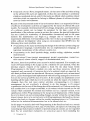
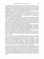
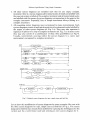
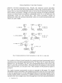
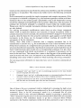
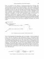
Fig. 2. Original syntax diagrams for type, simple type and field list
Let us show this modification of syntax diagrams by some examples. We start with
the three syntax diagrams for type, simple type and field list of Fig. 2. The syntax
diagram for field list has already been modified by replacing the subdiagram for the
variant part by a nonterminal node and creating an own syntax diagram for it.
328
G. Engels, R. Gall, M. Nagl, and W. Sch/ifer:
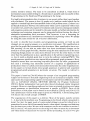
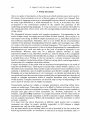
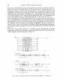
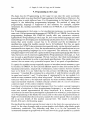
Since each type definition alternative is regarded as a complex increment, the syntax
diagram for type is modified such that it contains only a multiple alternative of
nonterminal nodes each of which corresponds to an other syntax diagram. This
modification is done by inline insertion of the syntax diagram for simple type, then
replacing each type alternative subdiagram by a nonterminal node and by creating
new syntax diagrams. The resulting syntax diagram (cf. Fig. 3. a) corresponds to a
menu nonterminal having a menu representation on the screen (cf. Fig. 1. c).
Some type definitions may be declared by the user as packed type. This decision of a
user is included because of certain reasons within the frames for the type definition
alternatives (cf. Fig. 1. d) and, therefore, also in the corresponding syntax diagrams.
This implifies that the terminal node labelled by packed in the syntax diagram for
type (cf. Fig. 2. a) has to be inserted into each of these type definition alternatives.
For example, the syntax diagram for a record type declaration is modified as given in
Fig. 3. b.
Since each record type consists of a possibly empty semicolon-list of record
components, each list element forms a separate complex increment, described by the
syntax diagram record component of Fig. 3. d.
type
type identifier ]
-1 enumeration type I
~.
record type
l "
--1 subrangetype
I
_t
-1
.[
pointer type
]
array type
]
_r record type
-t
:_f
_i
set type
1l
1
j
-t
j
file type
~
3. a
field list
-(-~
3. b
field list
j
3. e
record component
identifier
3. d
Fig. 3. Menu and complex increment nonterminals corresponding to a record type
Software Specification Using Graph Grammars
329
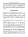
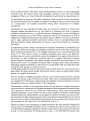
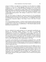
If there is a sequence of optional p a r t s in a syntax diagram, the questions are
presented to the user like a menu. Here, however, the user is not allowed to choose in
arbitrary order. For example, this is done for the declarations in a block, where each
declaration part is optional (cf. Fig. 1. a). The corresponding modified syntax
diagram is given in Fig. 4.
An analogous situation occurs if the user is asked for the continuation of a cycle (and
in this case also for an option) as given in Fig. 3. c. Now, the correspondence of
syntax diagrams of Fig. 3 to the menus and frames of Fig. 1 is obvious: Fig. 3. a
corresponds to the 1-from-n selection in menu 1. c, Fig. 3. c and Fig. 4 to the menu of
Fig. 1. e and 1. a, respectively, whereas the syntax diagram of Fig. 3. b and 3. d
correspond to the frames of 1. d and 1. f.
declaration alternatives
label decl part
-I
var decl part
~ - ~
const decl part
type decl part
} "~
func decl
proc decl
Fig. 4. Menu nonterminal corresponding to a sequence of options
5. The Module Graph
As mentioned in the introduction incremental mode enforces high-level intermediate data-structures (intermediate codes). For Programming in the Small, i. e.
for a single module, this data structure is called module graph. As Programming in
the Small also means runtime support, transformation etc. of modules (cf. e.g.
[Na 80]) the internal structure has to be chosen not only to cover the aspect of
syntax-aided editing. AII these activities may need further information to be added
to or deleted from the internal data structure. This is the reason that the
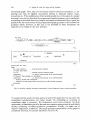
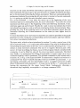
intermediate code is a graph and not only a tree. The module graph (e.g. Fig. 5) is a
labelled graph where labelled nodes in most cases express lexical units or increments
and where labelled edges express context free as well as context sensitive relations.
To any string increment there corresponds a graph increment. The module graph is
nothing else than a composition of graph increments.
An empty simple increment corresponds to a node labelled with a place holder label
(abbr. by ph). So, an empty increment for an identifier is represented by a n o d e
labelled with ph_id. A full simple increment corresponds either to a single node
labelled with a lexical unit for an indentifier, literal etc. or, in the case of a variable or
an expression, it is internally represented by a subgraph of the module graph. This
subgraph essentially is the abstract syntax tree.
330
G. Engels, R. Gall, M. Nagl, and W. Schfifer:
An empty complex increment is described by a graph the nodes of which are labelled
with concrete syntax symbols or with nonterminal symbols of the modified
grammar of section 4. The latter ones are indicated as placeholder nodes. For a
complex increment there is always a start and an end node both being connected by
an ei-edge (for end of increment) if this relation is not expressed by other edges.
Graph increments corresponding to the inner increments of a complex increment
are connected to the start node of the complex increment using different labelled
edges: e. g. c-edges for the components of a record, td-edges for indicating a type
definition, n-edges for a denotation to a construct etc. If the complex increment is
partially expanded or full then some or all of nodes labelled with the nonterminals
corresponding to the inner increments have been replaced by nodes or subgraphs.
Besides the edges indicating inner graph increments we need edges of a certain label
to indicate the order of increments. This order (1) may be enforced by the syntax of
the programming language (as the order of declarations in PASCAL) but (2) it is also
necessary to express the order in which increments (the order of which is arbitrary
corresponding to the programming language) have been put in by the user. These
edges are drawn without a label in the following figures. This order also gives the
order of elaboration of declarations and execution of statements of a given module.
ei
Fig. 5. Module graph
Further edges are needed to express context sensitive relations between increments
or parts thereof. Especially, any applied occurrence of a data object must have a
declared occurrence. The same holds true for type identifiers, labels, and procedures
and functions. In the example module graph of Fig. 5 for example there is an o-edge
indicating that the PERSON-node within the object declaration is an applied
Software Specification Using Graph Grammars
331
occurrence to the PERSON-node within the type declaration. These context
sensitive relations especially show the advantage of the graph as model for the
internal data structure. The PERSON-node is kept twice in the module graph to
have a simple one-to-one correspondence between the module graph and the source
text on the screen.
Further edges, which are not drawn in Fig. 5 are necessary e.g. for simply handling
cursor movement but also for other technical reasons arising in the context of
evaluation and execution of the module graph.
Nodes labelled with nonterminal symbols represent either a certain simple
increment (e. g. ph_ id) or complex increment, or a class of complex increments (e. g.
ph_ td for type-definition) or a list of simple or complex increments (e. g. ph _idl or
ph_ stmtlst for identifier list or statement list). In either case the nonterminal symbol
exactly specifies the kind of admissible input to be asked by the user. This is
especially necessary for the full mode to be explained later.
Finally we have to introduce the cursor node. This node represents the place where
editing (but also any other action) takes place. The cursor node, therefore, is the
graph representation of the screen cursor.
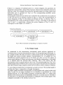
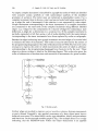
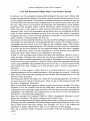
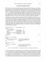
The translation scheme pursued in IPSEN is given in Fig. 6. Corresponding to the
input of editing commands the module graph is altered appropriately. The source
code displayed on the screen is generated from the module graph, i.e. the source text
is not kept in storage, too. This module graph may now be evaluated to find out,
whether the (partial) program has some property, it may be transformed to get some
property, or executed. This execution may also happen after having instrumented
the module graph by some consumption counters, or this execution may only go on
if some test conditions hold true or after resumption of the user at some breakpoints.
Also, execution may take place only after having translated the module graph to
some other more machine adequate level (incremental compiling). All these aspects
of further activities around the module graph are not studied in this paper (cf. e.g.
[Na 80]). Now, the reader may understand that the module graph is the center of all
activities corresponding to Programming in the Small.
input of _ _ . ~ ~
tmodule~
commands
/source ! / "
Changes
on
/- t-f
~
,.. /
-~
module
translation
r-tn
.. ~ a p h . - - generation of-.- / / . / /s.l
\\
~ ~text repre- " /
It
\\
sentation /
\
I
\
/
/not
\ evaluation
( regarded \ transformation
here
test
instrumentation
execution
~> other level
(execution)
Fig. 6. Translation scheme for Programming in the Small within IPSEN
332
G. Engels; R. Gall, M. Nagl, and W. Sch~ifer:
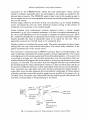
6. Construction of a Programmed Graph Grammar for Input Mode
In this section we will show that module graph changes due to syntax-aided editing
commands can easily be specified using a sequential programmed graph grammar.
Furthermore, this graph grammar can systematically be derived from (1) the
modified (context free) string grammar of the underlying programming language of
section 4, (2) the context sensitive relations of this language, and (3) the idea of the
user interface we have outlined in section 2. It should be noted that detection of
errors and recovery corresponding to errors made by any input of the user is not
handled here.
A sequential programmed graph grammar consists of a start graph, a set of
productions, and a set of control procedures which control more complicated graph
rewritings. A production consists of a left-hand side (the graph to be replaced), a
right-hand side (the graph to be inserted) and an embedding transformation (which
says, how incoming and outgoing edges are transferred, when the right-hand side
replaces the left-hand side). For the embedding transformations needed in this paper
the notation of nearly any graph grammar approach can be used (cf. [CER 79]). A
control procedure is nothing else than a flow diagram the actions of which are
applications of productions or calls of other control procedures. However, an action
may also demand an input of text corresponding to a simple increment.
Furthermore, there are decision notes where an input of the user is expected to
decide the edge to proceed further in execution. Control procedures are denoted here
in a PASCAL-like fashion in order to make use of control structures. A direct
sequential programmed derivation step from graph g to graph g' by control
procedure c_i, which is abbreviated by
g - - s p - - ) g',
c_i
is nothing else than a sequence of elementary sequential derivations with
productions p_j which are named by action nodes of a control path through c_i and
all the control procedures called within this path. A sequential programmed
derivation then consists of a sequence of such direct sequential programmed
derivation steps. The aim of introducing control procedures is to describe
modifications of a graph which are the result of a sequence of simple steps rather
than the result of a single step.
The construction of the graph grammar is done in two steps starting with the
modified syntax diagrams the nonterminal nodes of which are either simple
increment, complex increment, or menu nonterminals: (1) The control procedures
are nearly derived automatically. (2) The second step then consists of writing down
the corresponding graph productions for these control procedures. The shape of the
graph increments to be inserted we have already indicated in the last section. Let us
demonstrate this procedure for getting the graph grammar specification first for
menu nonterminals. Fig. 3. a shows the syntax diagram for type. This syntax diagram
directly corresponds to the menu of Fig. 1. c. The translation of the syntax diagram
of Fig. 3. a into the control procedure of Fig. 7. a is trivial. A menu nonterminal
representing a 1-from-n selection is translated into a case-statement where in each
Software Specification Using Graph Grammars
333
case-alternative the control procedure for the corresponding complex increment
nonterminal (only type identifier is a simple increment nonterminal) is called.
Analogously, the menu nonterminal field list of Fig. 3. c representing a loop followed
by an option is directly translated into the control procedure of Fig. 7. b. Please note
that for this kind of syntax diagrams no graph productions have to be developed as
the modification of the module graph is only done in the control procedures called
within menu type control procedures. Thus, the function of control procedures for
menu nonterminals is only to call the control procedures corresponding to the
selection the user has made.
control procedure type def;
begin
case "user choice" of - - by input of a cmd by selection
IT: type_id;
IET: en_ type_def;
ISRT: sr_type def;
IPT: ptr_type_ def;
IAT: ar_type def;
IRT: rc type def;
IST: set_type_def;
IFT: file_type_def
esac
end;
7. a
control procedure rc_field_list;
begin
while "another record component" do - command IRC by selection
rc_comp decl;
if "variant_part" then
- - command IVP
rc_ varpart
end;
7.b
Fig. 7. Menu nonterminals and corresponding control procedures
The next type of nonterminals to be discussed is the complex increment nonterminal.
Again, the translation into a control procedure is straightforward. The structure of
the (modified) syntax diagrams of Fig. 3. b and 3. d can directly be found within the
procedures of Fig. 8. At the beginning of each control procedure, however, there is
an application of a skeleton production which inserts the concrete syntax nodes and
some placeholder nodes in the module graph as we show in detail below. At the end
of each control procedure we find the application of a technical control procedure
e r a s e - o p t - p h s which deletes some placeholder nodes which are not necessary
further. The function of the control procedure rc type_def mainly is - besides of
applying technical productions - to call the control procedure rc_field _list. This is
because the frame for record type definition has no input fields for simple
increments. The frame for record component declaration contains an input field for
a list of identifiers but not the corresponding type definition. Here, opposite to
rc_ f i e l d list, we have a nonempty sequence. Therefore, here an until-loop instead of
a while-loop is used. For each identifier put in by the user some context sensitive
334
G. Engels, R. Gall, M. Nagl, and W. Sch/ifer:
check is necessary here to avoid that this identifier has already been used for another
component within the actual record type definition. The insertion of the subgraph
corresponding to the type definition of any component is done within the procedures
which are called within the control procedure type_def.
control procedure rc_type_def;
begin
rc_skeleton; -- frame here contains no input field, it is immediately
if "packed" then change_to_packed_rc; - - transferred after having
rc_field_list;
- - decided for packed/unpacked
erase_ opt_phs
end;
8.a
control procedure rc_comp_decl;
begin
rc_ comp_skeleton;
repeat
rc_comp_id - - componentidentifier is taken as input
- context sensitive check
until break symbol;
frame is closed and transferred
type_def;
- insertion of type definition within the control
- procedurescalled in type def
erase opt_phs
end;
8.b
Fig. 8. Complex increment nonterminals and corresponding control procedures
Let us now explain how the productions for the two control procedures rc_type_def
and rc _ comp _ decl look like (cf. Fig. 9). The production rc_ skeleton inserts a pair of
rec-end-nodes, but also changes the placeholder node from p h _ t d to ph_fl where fl
stands for record field list. The cursor is moved to the ph_fl-node. The embedding
transformation is such that all edges of node 1 of the left-hand side are transferred
without any change to node 1 of the right-hand side and the same happens for edges
incident to node 2 of the left- and right-hand side, respectively. This is indicated by
E id (1 ; 1) and E_ id (2; 2). Analogously, the production rc_ comp_ skeleton inserts
two further placeholder nodes, namely for identifier list and for type definition. The
ph_fl-node for record field list is still existing. The cursor now is at the ph_idl-node,
as identifiers for record components are expected. The cursor-node gets again an
identical embedding while the embedding of the node 1 of the left-hand side is now
transferred to node 1 and 3 of the right-hand side. This means both that the ph idlnode as well as the ph_fl-node of the right-hand side have an incoming c-edge after
the application of this production. The production rc_comp _id inserts a record
component identifier leaving the ph_idl-node available as further identifiers are
expected. Note, however, that this identifier node is only inserted if within the same
record type definition there is no record component with the same name. This is
expressed by the negative application condition drawn here as a subgraph separated
from the left-hand side by a dotted line marked by NOT. The label id within this
production stands for an arbitrary identifier. So, we furthermore have some
Software Specification Using Graph Grammars
335
primitive two-level mechanism here. Finally, the technical control procedure
erase_opt_phs erases the optional placeholder nodes of the actual increment. The
reason that we erase the placeholder nodes is that in the full incremental mode (see
below) nearly everywhere a change can occur and, because of storage and lucidity
reasons, we cannot insert everywhere a placeholder node. So, to act uniformly, the
placeholder nodes are also deleted here. This control procedure consists of
productions where the optional placeholder nodes are erased unconditionally and
which are quite simple.
1
rc_ skeleton
~
4
E_id(1; 1)
:: =
e1~3
~ 2 E
_ id (2; 2)
2
4
rc_comp_ skeleto
.. _
2
C
E_id(1 ; 1,3)
E_id (2; 2)
3
2
/
rc_comp_id
//
1
1
E_id(l; 1,3)
"
"2
Fig. 9. Graph productions of control procedures rc_type_ de/', rc_ comp_ decl
For another and more typical example of a complex increment nonterminal and its
translation into a control procedure look at Fig. 10. There, Fig. 10. a gives the syntax
diagram for a for-statement, Fig. 10. b the corresponding frame at the screen, and
Fig. t0. c gives the control procedure. The productions are analogous to the example
above and, therefore, are not given here. This example will be picked up again in
section 8.
For simple increment nonterminals we give no example in this paper. If a simple
increment is only a node label on the module graph level, then the control procedure
is only the application of a trivial relabelling production (eventually together with a
context sensitive check). If, however, a simple increment is internally represented as
a graph rather than a single node, then this graph has to be built up and embedded in
22 Computing31/4
336
G. Engels, R, Gall, M. Nagl, and W. Sch/ifer:
the m o d u l e graph. Then, also:a lot of context sensitive checks are necessary, i.e. for
m a k i n g sure t h a t all a p p l i e d occurrences belong to declared objects, types,
p r o c e d u r e s etc. T h i s modification,of the m o d u l e g r a p h due to the i n p u t of a s i m p l e
i n c r e m e n t can also be described by p r o g r a m m e d g r a p h g r a m m a r s in an a n a l o g o u s
p r o c e e d i n g as sketched a b o v e for c o m p l e x i n c r e m e n t n o n t e r m i n a l s . Here, again, the
guideline for the c o n s t r u c t i o n of the p r o g r a m m e d g r a p h g r a m m a r is the context free
g r a m m a r which, however, in this case is not modified as these increments are
r e g a r d e d to be simple at the user interface.
for strut
(
.[ statement }
10. a
........
: for 9
.
label
"
.
.
.
.
.
.
.
.
.
.
.
variable_id
:
[] downto
.
.
.
.
.
.
.
.
expression
.
.
.
.
.
[]
.
.
.
to
.
.
.
.
.
do
.
expression
statement
IO.b
control proc for stmt;
begin
for_stmt skeleton;
- - loop upward as default
if "label" then label;
var_id;
--includes context sensitive check
expression;
- - c.s. check; construction of an internal graph
if "downto" :then ~change_to _downloop;
expression;
- - c.s. check; construction of an internal graph
- - frame is closed and transferred;
- insertion of strut graph within control procs called within statement
statement
end;
10.c
Fig. 10. Another complex increment nonterminal: syntax diagram, frame, control procedure
To s u m m a r i z e the graph rewritin9 approach used in this p a p e r here we can state: the
e m b e d d i n g t r a n s f o r m a t i o n s are r a t h e r simple. N o relabelling or reversing of
e m b e d d i n g edges is necessary. W e f u r t h e r m o r e need some primitive two-level
m e c h a n i s m , as identifiers p u t in b y the user m u s t replace m e t a s y m b o l s of n o d e labels
thereby p r o d u c i n g so-called p r o d u c t i v e procklcfions. F i n a l l y , we m a k e use of
negative a p p l i c a t i o n conditions. T h e g r a p h g r a m m a r p r e s e n t a t i o n of this p a p e r is
c o m p l e t e l y informal, for ~precise definitions see [ N a 79].
Software Specification Using Graph Grammars
337
7. The Full Incremental Editing Mode: User Interface Revised
In section 2 we have sketched syntax-aided editing for the input mode. Menus and
frames are alternatively offered to the user to select syntactical constructs and to put
in their simple increments. All necessary syntactical checks are carried out and, on
the other hand, the concrete syntax is generated by the system rather than put in by
the user. The cursor is set forward automatically. The building-up of the module
graph has been specified within control procedures which recursively call each
other. The user is only asked to select between alternatives possible in a special
situation. Now, in the full incremental editing mode there is no sequential and fixed
order in which editing commands are put in by the user. Any order of inserting,
changing, deleting, or cursor moving commands is possible. To illustrate this, let us
again consider a dialog fragment (cf. Fig. 11).
In section 2, we have sketched the menu selection mode for putting in commands, i. e.
commands are activated only by being selected from a menu. For briefness reason,
commands can also be put in by text string for the command name. This mode is
intended for the more experienced user. We call this text input mode for commands.
It is taken for the next example. In this mode the frames may also have a simpler
shape. Furthermore, there is some mechanism to switch between these different
command input modes which is not explained in this paper.
In Fig. 11, a the working cursor is before an if-then-else-statement, which we want to
refine partially. Pressing three times the next-button positions the cursor to the
location, where a boolean expression is to be put in. (Pressing it once the compound,
if twice the if-then-else-statement is marked.) Now, within the command area we put
in the command IBE for Insert Boolean Expression (cf. Fig. 11. b). (I for Insert in this
case would have been enough, as at this position only a boolean expression is
allowed.)
As above, a frame appears which, however, is unstructured here as we regard a
boolean expression to be a simple increment. After putting the string A > B into the
input field of the frame and pressing the next-button the working cursor is at the
position of the then-part.
This then-part shall be left empty for a while. So, by pressing again the next-button,
we move the cursor down to the else-part. Then, we put in the command name IAS
for Insert Assignment Statement.
Here, a structured frame appears, which contains the becomes symbol. The input
sequence A (for the variable and the left-hand side), next-button (for moving the
command cursor to the right-hand side) and 1 (for the right-hand side) completes the
assignment. The following next-command moves the cursor to the next position,
which here is the following assignment.
Here, for example, the command DAS for Delete Assignment Statement would
delete this statement. The dialog could proceed anyhow now.
What we can learn from a full mode editing step is that an arbitrary increment may
be empty, partially expanded, full before being incrementally edited but it may have
one of these forms even after editing. For example, in Fig. 11.. b the if-then-else
statement is empty, afterwards in Fig. 11. f its then-part is still missing.
Now, let us explain, which commands are possible in the full incremental editing
mode.
22*
338
G, Engels, R. Gall, M. Nagl, and W. Sch/ifer:
Ilk
begin
if
else
end;
\
/
B:=2;
* :g:~,'gg g S * g
3 times
begin
if 9
dse
end;
I
B:=2;
then
g@ gg gg g:g g gg g 8.*
>
then
g * g g ~gg g @ g g g
GIVE COMMAND: 9
//)
GIVE COMMAND: 9
//
tl.a
I:
E INSERT BOOLEAN EXPRESSION
[ boolean expression
IBE
I
[
ll.b
/begin
if A > B then
A>B
I
ll.c
else
)
end;
B; =2;
GIVE COMMAND: 9
IAS INSERT ASSIGNMENT STMT
I 9
._
~/1
~L-> IAS
ll.d
/begin
if A > B then
else
A:=I
end;
:."= 2;
ll.f
Fig. 11. Full incremental mode: user interface
There are insert c o m m a n d s which can be used to fill an existing gap for a simple
increment (e.g'. for boolean expression if the enclosing if-then-statement is already
generated) or to generate a gap and possibly fill it (e. g. for inserting an assignment
statement within two already existing assignments). Analogously, any complex
increment can be inserted and its frame can be filled (left blank, be partially filled, be
completely filled). Inserting a complex increment means also the insertion of
concrete syntax nodes and placeholder nodes. Finally, a partially expanded or full
increment m a y be inserted which is the result of some previous dialog activity (see
below) which means that some graph has to be embedded in the module graph.
As in most situations there are several possibilities for expansion, insert is not a
c o m m a n d but a command group. IAS or I B E are commands. However, in some
Software Specification Using Graph Grammars
339
situations the c o m m a n d is clear from the context and, therefore, only the command
group has to be specified. This remark also holds true for the following command
groups.
D e l e t e commands are possible for simple increments and complex increments. If the
increment to be deleted is obligatory (e. g. the boolean expression within an if-thenstatement) then in the module graph a placeholder node is left behind after having
erased the subgraph corresponding to the increment. Otherwise, if the increment is
optional the increment subgraph is completely erased within the module graph.
Please note, that for complex increments deletion means that all inner increments
are also deleted.
For making incremental modifications easier there are also c h a n g e commands
which avoid (a repetitive) deletion and insertion of simple increments within a
complex increment. If, for example, the c o m m a n d CFS (for Change For-Statement)
is given, then the frame for the actual for-statement again appears and all simple
increments in the frame can be changed (without touching all possible inner
increments of the for-statement).
Finally, there often arises a situation that a complex increment has to be
transformed to another one, e.g. the transformation of an if-then-statement into an
if-then-else-statement, of a compound into a procedure body etc. As there are m a n y
situations feasible and reasonable a big bunch of commands would result if for any of
these transformations there would exist a corresponding command. For this, there
are save commands with which an increment or a sequence of increments can be
saved to be used later. This means that a more or less big part of the module graph
must be stored such that it can be inserted at any admissible position later only by
specifying some name (which is asked for when executing the saving command).
For moving around arbitrarily we must also have c u r s o r m o v e m e n t commands (cf.
Table 1).
Table 1. Cursor movement commands
~
~
\
F
Command"next" and "pred": to next or predecessing increment in the most detailed
structure (in graph and source text).
Command"down" and "up": to following increment or to increment heading of the actual
increment without entering the details of the actual or heading increment.
Command"hierarchy up" and "leave": go up in nesting hierarchy,or leaveactual increment
and then take next (eventually again leave and next increment).
One of them is the n e x t - c o m m a n d which is initialized by pressing the right arrow
button. In section 2 this button was understood as the end symbol of an insertion
command. Now, in the full incremental mode it is a c o m m a n d like all other
commands which is only activated differently, namely by pressing a special key.
"Next" means moving the cursor to the next increment if we follow the most detailed
source structure. This sometimes means to go into a structure (from if-thenstatement to the boolean expression within the if-then-statement), to go to the next
340
G. Engels, R. Gall, M. Nagl, and W. Sch~fer:
structure on the same level (from the boolean expression to the then-part of an ifthen-statement), but also to go to the next structure at a higher level (from the thenpart to the increment following the if-then-statement). The pred- command (pred for
predecessor) initiated by pressing the left arrow key is inverse to the next command,
i.e. it is going up within the most detailed source structure.
The 9o-up-command ( N key) takes the cursor up to the beginning of the next
increment upward in nesting hierarchy, the leave-command ( 2 key) exits the actual
increment and then goes to the beginning of the next following increment, if any,
otherwise again up and forward. Finally the ~ and ~ cursor movements have been
introduced for going down and up without entering the details of an increment. Thus,
pressing the ~ key if the working cursor is at an if-then-statement means that the
increment following the if-then-statement on the same (or next higher level) is
marked.
It is clear that these cursor movement commands can easily be specified on the graph
grammar level by writing the corresponding control procedures and their elementary cursor movement productions.
The input mode, which we have introduced in section 2, is only a special case of the
full incremental mode, i.e. it is only some abbreviation. One step in this direction of
interpreting the input mode in this way was to understand the pressing of the ~ key
always as some movement command. The next is to regard a frame as part of the
source: A frame is nothing else than a cutout of the program which is enriched with
comments. It can be filled but also left by cursor movement commands. The third
step, finally, is to understand the filling of input fields as implicit input of an insert
command together with its parameter. The possible command is clear within such a
situation. So, in Fig. 12 the input L O O P V is understood as implicit activation of a
command IV for Insert Variable identifier with text L O O P V as parameter, ~ as
movement command to the next placeholder node, 1 as implicit activation of IEX
(Insert EXpression) with parameter 1. A frame can be left by a 2" command, here
leaving the expression for the upper bound blank. Analogously, choosing a
downward-loop implicitly corresponds to a change command CDL.
//
--..
- - - - - - - - _
***********************************************************************************
.......
label
:
[] downto
for .11.. . . . . . . . . : = . . . . . . . . . . . . . . . . . . . .
variable_id
expression
[] to
expression
do
statement
LOOPV ~
r
IV
l
1
l
NEXT IEX
selection
T
evtl. CDL
~"
l
LEAVE
Fig. 12. Input mode as special case of the full incremental editing mode
Software Specification Using Graph Grammars
341
8. Control Procedures Revised
W h a t was the execution model for sequential p r o g r a m m e d rewriting steps we h a d for
the input mode c o n t r o l p r o c e d u r e s of section 6? There, the c o n t r o l p r o c e d u r e s have
been a c t i v a t e d b y (recursive) calls. T h e o r d e r of activation was fixed within the
bodies of the c o n t r o l procedures. F o r example, in the c o n t r o l p r o c e d u r e for_ stmt of
Fig. 13. a it is fixed t h a t after a p p l y i n g a skeleton p r o d u c t i o n the control p r o c e d u r e s
v a r _ i d , expression, expression, a n d s t a t e m e n t are called in this order. T h e user was
o n l y asked, if one of m o r e alternatives h a d to be selected. T h e cursor m o v e m e n t in
the g r a p h as well as on the screen was u n d e r s t o o d to h a p p e n a u t o m a t i c a l l y .
In the full i n c r e m e n t a l m o d e no p r e d e t e r m i n e d a n d a u t o m a t i c activation of c o n t r o l
p r o c e d u r e s can t a k e place. T h e r e a s o n is t h a t the user is allowed to p u t in increments
in a n y order, leave p a r t i a l l y e x p a n d e d increments, come b a c k to those increments,
delete i n c r e m e n t s etc. Here, all c o n t r o l p r o c e d u r e s are directly activated in a n y o r d e r
by the user r a t h e r t h a n b y some k i n d of pregiven o r d e r fixed in the bodies of the
control procedures. This direct activation can be d o n e explicitly b y specifying a
c o m m a n d (by i n p u t of a c o m m a n d n a m e or b y a selection) or implicitly by filling out
the i n p u t fields of a frame.
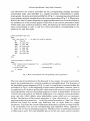
control proc for stmt; - - corresponding to
begin
for_strut skeleton; - if "label" then label; - - corresponding to
var_id;
corresponding to
expression;
corresponding to
if "downto" then change-to-downloop; - - c.t.
expression;
- - corresponding to
statement
end;
IFS
IL
IVI
-IEX
CDL
IEX . . . .
13.a
control proc I For Statement;
begin
exit if not for_stmt allowed; - - check only for non-menu mode
for_stmt_skeleton
- contains implicit NEXT call
end;
show frame
13.b
control proc I Var Id;
begin
exit if not var id_allowed;
var_id
end;
check not necessary if impl. activ.
- - corr. frame only shown if expl. activ.
- - context sensitive check
Fig. 13. Control procedures for inserting a for-statement: input mode and full mode
So, if we write the c o n t r o l p r o c e d u r e for a f o r - s t a t e m e n t in the full i n c r e m e n t a l m o d e
(cf. Fig. 13), then this c o n t r o l p r o c e d u r e need n o t c o n t a i n the a c t i v a t i o n of label,
var _ id, expression, a n d s t a t e m e n t as these c o n t r o l p r o c e d u r e s are directly activated.
Also, the cursor m o v e m e n t need n o t be c o n t a i n e d n o r d o n e a u t o m a t i c a l l y . Finally,
the c h a n g e from an u p w a r d - l o o p to a d o w n w a r d - l o o p is directly a c t i v a t e d b y a
c o r r e s p o n d i n g change c o m m a n d . So, the control p r o c e d u r e s in the full i n c r e m e n t a l
342
G. Engels, R. Gall, M. Nagl, and W. Schfifer:
mode (cf. Fig. 13. b) consist only of a skeleton production for complex increments or
some relabeIIing production or building up control procedures for simple increments
which may contain context sensitive checks. The first is the case if, for example, a
loop variable is inserted the second if an expression is put in. However, because of
the arbitrary order of activation, at the beginning of each control procedure for the
full mode, there must be a check whether the execution of this control procedure is
allowed at all. This check need not be carried out, if the command is selected in menu
mode and it is also not necessary for directly but implicitly called insert commands.
Now, again, let us compare the execution model we had for input mode in section 6
with that for the full mode we have here (cf. Fig. 14). For input mode we had one
rather complex programmed graph rewriting step which was driven by the
execution of a single control procedure c prog_im (for program and input mode)
corresponding to a PASCAL module (program or subprogram). The mutual
activation of control procedures was already fixed in the bodies of the control
procedure c_prog_im and its subordinate control procedures which recursively
called each other. User input was only necessary for selection and input of simple
increments. This complex rewriting step directly corresponds to a derivation of the
source program within the PASCAL string grammar. The graph grammar for input
mode is nothing else than a rather direct translation of the corresponding string
grammar.
In the full mode we have no correspondence to a string derivation as the module and
also the internal graph is usually partially expanded before and afterwards.
Furthermore, it can be changed arbitrarily. So, the situation of the full mode is that
we have a sequence of sequential programmed derivation steps with control
procedures c_ i_j selected by the user. If such a control procedure is not admissible in
a special situation, then its execution is rejected because of the check for applicability
at the beginning of each control procedure. Any of these graphs g j of the full mode
graph grammar is also the result of a derivation of the input mode graph grammar if
one additionally allows to leave increments empty when building up the source code.
The application of a programmed step corresponding to full mode on graph g _j and
leading to graph g_j + 1 can be imagined as changing the derivation of g _j within
the input grammar in order to get a derivation of g_j + 1 within the input grammar.
There are close relations between these two grammars. It is clear that the input
grammar is properly contained in the full mode grammar in the sense that for any
input grammar derivation there is a full grammar derivation but not vice versa.
input mode :
g_0-
full mode:
g_0---sp--@
c i_l
g_0
-sp--@
c prog_im
g_n
g_l
--sp--@
c_i 2
g_2 ... - -
sp - @
cin
--sp
-) g_n
c_prog fm
Fig. 14. Programmed derivations in input and full mode
g_n
Software Specification Using Graph Grammars
343
Now, we summarize this sequence of sequential programmed rewriting steps
corresponding to a user session of full mode editing in order to get a complex step
with one control procedure. This control procedure c_prog_fm (for program and
full mode), of course, then has the structure of a while-loop (cf. Fig. 15). As long as
commands are put in by the user, the while-loop is executed. Depending on the
actual command a corresponding control procedure is called. Commands can be
input commands, delete commands, change commands, save commands, cursor
movement commands, but also other commands arising in the context of
evaluation, transformation, execution, testing, and monitoring of modules.
The module graph acts as a global data structure for all control procedures. The
start graph of a session using the full mode grammar is the axiom graph of the graph
grammar or the result of a previous session. The calling hierarchy of the recursively
called control procedures of the input mode is implicitly contained in the module
graph.
control proc prog_fm;
begin
while "command given" do
case "command" of
CMDI: call_of_control_proc to_CMD1;
--
commands:
D
,,.
C
,,.
S ...
CMDn: call of_control,_proc_to_CMDn - esac
cursor,
etc.
od
end;
Fig. 15. Uppermost control procedure for full incremental mode
Now, if we summarize the proceeding taken in this paper, we get the picture of
Fig. 16. We have seen that we can systematically develop a programmed 9raph
9rammar for syntax-aided editing. The input of this proceeding is a clear idea of the
user interface, and the context free as well as the context sensitive syntax of the
underlying programming language. The user interface leads to a modification of the
context free string grammar, thus influencing the programmed graph grammar
indirectly. On the other hand, we have also a direct influence as in the control
procedures we describe transfer of frames, which questions are given to the user etc.,
too. This systematic development is applicable for the input mode as well as for the
full editing mode. Furthermore, we have seen that the input mode is only a special
case of the full mode.
user interface
~> c.f. string . . . .
grammar
t2>p graph <]. . . .
grammar
context sens.
rules
Fig. 16. Summary of the proceeding taken for input as well as full mode
344
G. Engels, R. Gall, M. Nagl, and W. Sch/ifer:
9. Programming in the Large
We claim that for Programming in the Large we can take the same systematic
proceeding which was described for Programming in the Small above. However, the
starting point is quite different here. For Programming in the Small the base of
support is the underlying programming language. No method of using this
programming language is supported at this moment, for example, stepwise
refinement. So, making reasonable or foolish use of PASCAL is not influenced by
IPSEN.
For Programming in the Large, i.e. for specification purposes, we cannot take the
same view. Old programming languages as FORTRAN, or COBOL, but also newer
programming languages like PASCAL hardly offer any constructs evidently
applicable for Programming in the Large. So, here some formal language and some
methodology for developing and maintaining specifications has to be offered. This
means that some module concept has to be selected and the development of
specifications using this module concept has to be facilitated. For this, we again
make use of all IPSEN characteristics (incremental mode, syntax-directed reaction,
command-driven input etc.). Also, the transformation of such specifications into an
existing programming language has to be supported. The necessity for a methodological support even arises for a quite modern programming language like Ada. In
Ada, there are a lot of constructs applicable for Programming in the Large, i.e. Ada
can be used as specification language. We feel, however, that their methodological
use should be facilitated in order to get elucid specifications. The reader may have
noticed that we mean only syntactical aspects here if we speak of specifications.
To speak of a module concept especially means to introduce certain necessary types
for modules. In IPSEN, we have chosen different types for data abstraction and for
functional abstraction, respectively. Furthermore, some relations between modules
have to be fixed. It is our belief that for this at least the following relations are
necessary: "A module B is contained in a subsystem A' and therefore is usable only
in some local context", and "A subsystem A' represented by its top module A is
usable as some common tool by other subsystems". In both cases a module exports
resources which have to be imported explicitly by other modules. Besides module
types and module relations a module concept consists also of a set of consistency
conditions (part of the context sensitive syntax).
Looking at existing programming languages then this module concept represents
some kind of extension to these programming languages, i.e. we must introduce
some new textual representation for these constructs. It is, however, not an
extension in the sense that a precompiler is planned to be written as, in the same way
as in Programming in the Small, the source code on the screen is generated from an
higher level intermediate data structure, namely the system graph. There is no place
left to go into details of this module concept here. The reader is referred to
[Ga 82, 83] and a forthcoming paper.
Having fixed the module concept the next step is to lay down its representation as a
9raph, i.e. the class of graphs used as system graphs: node labels, edge labels, graph
consistency conditions. The following step then is to fix the increments for
incremental changes on graph level as we start here with a graph model for a module
Software SpecificationUsing Graph Grammars
345
concept. Trivially, in our approach an increment is not the source of a complete
module as it is the case in those languages which have constructs for separate
compilation (as Ada, cf. e.g. [Na82]). Instead, increments are e.g. parts of the
module interface, i.e. of the export or import clause. After having determined the
graph representation and the kind of increments the abstract syntax on graph level is
roughly fixed. So, up to this point, we have some informal specification of the
corresponding graph grammar. This belongs to context free as well as context
",~ensitive aspects.
\\
The next step consists of fixing the string representation for this specification
language derived from the module concept. This is a formal programming language
for Programming in the Large but, as stated above, no compilation step in the
classical sense necessarily appears. This fixing is done in the form of syntax
diagrams.
Now, the proceeding of sections 2 - 8 of above can be adopted as all three inputs for
our proceeding are laid down. The derivation of the sequential programmed graph
grammar may of course lead to modifications of the informal graph grammar
specification mentioned above.
10. Conclusion
We have indicated that graph grammars are an appropriate specification mechanism for incremental changes arising in the context of syntax-aided
Programming in the Small and Programming in the Large, respectively. The
specification was carried out in a systematical or engineering-like way: It was the
result of a rather mechanical transformation using three inputs. The proceeding was
first demonstrated for the input mode and then extended to the full incremental
mode of Programming in the Small. Finally, we have sketched that it can be used
also for syntax-aided editing within Programming in the Large.
As stated in the introduction, the graph grammar specification has a two-fold
significance: On one side it makes precise which kind of problems occur and how an
abstract solution to these problems looks like. On the other hand this specification is
operational and, therefore, is a direct guideline for the specification of I P S E N in the
software-engineering sense.
What we pointed out is rather the method taken than its result. While the result is
depending on the programming language for Programming in the Small and the
module concept for Programming in the Large the proceeding, of course, is also
applicable for other programming languages and module concepts. Moreover, we
would claim that this proceeding can be applied for arbitrary dialog systems.
Especially, it is also applicable for the third problem area "organizational items"
within IPSEN. Because of this general suitability we have chosen the more general
title of this paper.
346
G. Engels, R. Gall, M. Nagl, and W. Sch~ifer: Software Specification
References
[BN 82]
[Bu 80a]
[Bu 80b]
[CER 79]
[DG 80]
[ES 82]
[Ga 82]
[Ga 83]
[Ha 82]
[JW 78]
[Me 82]
[Na 79]
[Na 80]
[Na 82]
[NEGS 83]
[Sch 75]
[TR 81]
Burkhart, H., Nievergelt, J.: Structure-oriented editors (Informatik-Fachberichte 30),
pp. 164-184. Berlin-Heidelberg-New York: Springer.
Buxton, J. N.: Requirements for the Ada programming support environment
("Stoneman"), United States Department of Defense.
Buxton, J. N.: An informal bibliography on programming support environments.
SIGPLAN Notices 15, 12, 17-30.
Claus, V., Ehrig, H., Rozenberg, G., eds. : Proceedings of the international workshop on
"Graph Grammars and their Application to Computer Science and Biology". (Lecture
Notes in Computer Science, Vol. 73.) Berlin-Heidelberg-New York: Springer.
Donzeau-Gouge, M., et al. : Programming environments based on structured editors - the
MENTOR experience. Techn. Report 26, INRIA, France.
Engels, G., Schfifer, W. : Specification of a programming support environment by graph
grammars. In: Proceedings of the WG'82 on "Graphtheoretic Concepts in Computer
Science", pp. 47 - 62. Mtinchen: Hanser.
Gall, R. : Structured development of modular software systems: the module graph as
central data structure. In: Proceedings of the WG'81 on "Graphtheoretic Concepts in
Computer Science", pp. 3 2 7 - 338. Miinchen: Hanser.
Gall, R. : Dissertation, Techn. Rep. IMMD-16-1, Universit~it Erlangen.
Habermann, N., et al. : A compendium of GANDALF documentation. Techn. Report,
May 1982, Department of Computer Science, Carnegie-Mellon University, Pittsburgh.
Jensen, K., Wirth, N.: PASCAL user manual and report, 2nd ed. New York: Springer.
Medina-Mora, R. : Syntax-directed editing - towards integrated programming environments. Techn. Report CMU-CS-82-113, Department of Computer Science, CarnegieMellon University, Pittsburgh.
Nagl, M. : Graph-Grammatiken - Theorie, Anwendungen, Implementierung. Wiesbaden: Vieweg.
Nagl, M. : An incremental compiler as component of a system for software development
(Informatik-Fachberichte 25), pp. 29-44. Berlin-Heidelberg-New York: Springer.
Nagl, M. : Einffihrung in die Programmiersprache Ada. Wiesbaden: Vieweg.
Nagl, M., Engels, G., Gall, R., Sch~ifer, W. : Software specification by graph grammars,
Proc. 2nd International Workshop in Graph Grammars. In: (Lecture Notes in Computer
Science, Vol. 153), pp. 267-287. Berlin-Heidelberg-New York: Springer.
Schneider, H. J. : Syntax-oriented description of incremental compilers (Lecture Notes in
Computer Science, Vol. 26), pp. 192-201. Berlin-Heidelberg-New York: Springer.
Teitelbaum, T, Reps, T.: The Cornell program synthesizer - a syntax-directed
programming environment. ACM 24, pp. 563-573.
G. Engels
Prof. Dr. M. Nagl
W. Sch~ifer
Angewandte Informatik
Fachbereich Mathematik
Universit~it Osnabrtick
Postfach 4469
D-4500 Osnabrfick
Federal Republic of Germany
Dr. R. GaI1
Lehrstuhl fiir Programmiersprachen
Universitfit Erlangen-N~rnberg
Martensstrasse 3
D-8520 Erlangen
Federal Republic of Germany