1
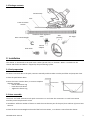
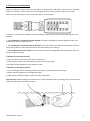
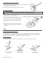
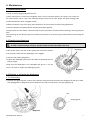
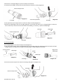
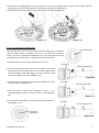
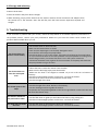
F
FR
Notice d'installation et d'utilisation
Français
Instructions for installation and use
English
Montage- und Gebrauchsanleitung
Deutsch
Installatie en gebruikshanleiding
Nederlands
Manual de instalación y de uso
Espanõl
Manual de instalação e utilização
Português
Manuale di installazione e di uso
Italiano
More languages on:
www.zodiac-poolcare.com
H 03 79 40 0 . B - 2 0 1 3 /06
EN
• Read this user manual carefully before installing, maintaining or repairing this appliance!
• The symbol
indicates important information that you must read in order to avoid all risks of harm to
persons or damage to the appliance.
• The symbol
indicates useful information.
• Exclusive use: Pool water cleaning (must not be used for any other purpose).
Warning
• It is important that this appliance be handled by skilled and apt persons (physically and mentally) having
received the instructions for use beforehand (through reading these instructions). Individuals who do not
meet these criteria should not approach the appliance in order to avoid exposure to dangerous elements.
• If the appliance suffers a malfunction: do not try to repair the appliance yourself, contact your installer.
• Do not operate the cleaner out of the water.
• Incorrect installation or use may cause serious damage to property or serious injuries (possibly causing
death).
• Keep the appliance out of the reach of children.
Make sure that the suction equipment installed in your pool and to which you have connected the hydraulic
cleaner, is compliant with applicable safety standards. To not block the pool suction nozzles, the cleaner
suction nozzle, or the cleaner hoses with any part of your body. Take care to keep your hair, loose clothing,
jewellery etc. away from the suction nozzles and other nozzles installed in the pool/spa or the cleaner.
WARNING ON THE USE OF THIS CLEANER IN A POOL WITH A VINYL SURFACE
Before installing your new pool cleaner, carefully inspect the coating on your pool. If the liner is fraying in
some spots, or if you notice gravel, folds, roots or corrosion due to metal on the inside face of the liner, or if
you notice that the support (bottom and sides) is damaged, do not install the cleaner before having made the
required repairs or having the liner replaced by a qualified professional. Zodiac® cannot, under any
circumstances, be held liable for damage to the liner.
As part of the continuous improvement process our products may be modified without prior notice.
H0379400.B EN– 2013-06
1
Contents
1. Information before installation and use ................................................................... 2
2. Installation............................................................................................................... 3
3. Use .......................................................................................................................... 6
4. Maintenance............................................................................................................ 7
5. Troubleshooting..................................................................................................... 10
1. Information before installation and use
1.1 Important
Check that your appliance has not been damaged during transport (shocks, broken parts, etc.). If you find any
problems don't hesitate to contact your reseller before using the cleaner.
1.2 Technical specifications
Hose length
Cleaner size (L x W x h)
Package size (L x W x h)
Cleaner weight
Packaged weight
Filtering capacity
Theoretical cleaning width
Minimum required filter pump power
Speed
10 x 1 metre sections
41 x 36 x 28 cm
102.8 x 41.5 x 22.4 cm
1.18 kg
6.8 kg
Pool filtering circuit
30 cm
½ HP
6.5 metres / minute
1.3 Recommendations for use
• In order to prevent suction related accidents, the suction line nozzles must be fitted with safety flaps.
Contact your pool professional for more information on this subject.
• Clean and empty the skimmer, pump and pool baskets before installing the cleaner, and then at regular
intervals.
• Always disconnect the cleaner before cleaning the pool filter or reversing the flow. After cleaning, leave
the filtering system running for five (5) minutes before reconnecting the cleaner.
Remove the cleaner from the pool before any chemical or shock treatments. Wait for at least four
(4) hours after shock chlorination before reinstalling the cleaner.
H0379400.B EN– 2013-06
2
1.4 Package contents
Cleaner body
Disk
Twist-Lock hose
section
Hose counterweight
Automatic flow regulation
valve
Flow tester
Antijamming
h l
45° angle
Conical
adapter
2. Installation
The cleaner is connected to the pool brush socket (suction line) or skimmer. Water is sucked into the
cleaner and the dirt and debris is trapped by the pool filtering system.
2.1 Pool preparation
• If there is too much dirt in the pool, remove it manually and then make sure the pool filter and pump are clean.
• Close the pool bottom drain.
• Point the return nozzles down, to ensure complete
cleaning coverage.
- Loosen the fixture ring
- Point the nozzle down
- Tighten the fixture ring
2.2 Hose assembly
The hoses are fitted with Twist-Lock quick connectors. Fit and twist the connectors on each hose section
until they come into place with a click.
• Assemble a sufficient number of hoses to reach the most distant part of the pool; then add two (2) more hose
sections.
• Place the hose counterweight at the end of the first hose section, i.e. at about 1 metre from the cleaner.
H0379400.B EN– 2013-06
3
Skimmer or brush socket
2 hose sections
Skimmer or
brush socket
Counterweight at 1
metre from the
cleaner
Counterweight at
1 metre from the
cleaner
2 hose sections
2.3 Hose connection
Start up the filter system and fill the pipe with water by placing the nozzle in front of a return nozzle until it is
completely full. Stop the pump.
Adjustment
valve
2.3.1. Installation on the pool brush socket:
Hose
• Connect the male socket of the hose to the automatic flow regulation
valve
• Fit the automatic flow regulation valve to the safety flap
Brush socket with safety flap
(Not included with the cleaner)
2.3.2. If your pool only has one skimmer:
The automatic flow regulation valve must be used for installations with only
one skimmer.
The valve adjusts the flow so that the pump and the cleaner operate correctly.
The default setting is defined to optimise cleaner performance, but three (3)
settings are possible to adjust the flow. The lowest setting corresponds to the
lowest flow. To adjust the setting, pull the handle and set the flow higher or
lower. The red lever can be used to open the valve and stop the cleaner.
Automatic
adjustment
valve
2.3.3. If your pool has several skimmers:
Connect the hose to the skimmer that is closest to the pump.
The elements to use to connect the hose and the procedure to
follow to install them depend on the type of skimmer.
1. Remove the skimmer basket.
2. Insert the valve flap and install the adjustment valve with the
arrow pointing to the bottom of the skimmer.
3. Select the elements that are adapted to your skimmer to finish
the installation. Fit the 45° angle to the regulation valve and the
male end of the hose above the angle, or fit the hose directly to the
regulation valve.
H0379400.B EN– 2013-06
45° angle
Adjustment
valve
Conical
adapter
4
2.4 Flow test and adjustment
Before installing the cleaner head, test and adjust to determine the ideal flow. Keep the hose immersed
and fit the connector to the end of the hose. Clip the flow tester to the connector and start the pump.
Check that the red indicator on the tester (side view) is on setting N°3.
If necessary, use the valves located in the pool technical room to adjust the flow so that the indicator is on
setting 3.
• For installation in a pool with a single skimmer, the flow is regulated by the flow regulation valve. The
red indicator must be in position N°3.
• For installation in a pool with several skimmers, leave the valve for the skimmer connected to the hose
open, then gradually close the other skimmer until the indicator is on setting 3.
• For installation on a brush socket, leave the suction line open and gradually close the skimmer line until
the flow reaches setting 3.
If the flow is in the low zone (0-2):
• Check and clean the pool filter and baskets if necessary.
• Check that the valves that control the suction lines are correctly open.
• Increase the flow regulation on the regulation valve.
If the flow is in the high zone (4-6):
• If you are using the brush socket, gradually close the valve until position N°3 is reached.
• Reduce the flow regulation on the regulation valve.
• Slightly open the bottom drain to reduce the flow a little more.
Stop the pump. While keeping the hose immersed, remove the flow tester by pressing on the pressure points
located on the sides of the quick connector.
H0379400.B EN– 2013-06
5
2.5 Installing the anti-jamming wheel
The anti-jamming wheel pivots on the hose to help the cleaner go around
steps and other obstacles in the pool.
Fit the anti-jamming wheel to the end of the last hose section.
2.6 Cleaner connection
In order to avoid all danger of injury, stop the cleaner suction pump before this step.
• Immerse the cleaner and fill it with water.
• When air bubbles have stopped coming out of the
cleaner, connect the hose to the cleaner by fitting
the quick connector on the anti-jamming wheel to
the connection tube until it fits into place with a
click.
• Let the cleaner sink to the bottom of the pool. Start
the pool pump to launch cleaning. The installation
is complete.
3. Use
3.1 Optimising cleaner performance
The robot follows the pool filter pump activation cycles, sucking and cleaning the entire pool surface using
random movements. The cleaner coverage rate depends on the shape of the pool and the available water
flow. Adjustments may be required in some pools to optimise the coverage rate.
3.2 Hose balancing
A correctly balanced hose must form a 45° angle between the cleaner and the bottom of the pool.
Incorrect balance
H0379400.B EN– 2013-06
Correct balance
Incorrect balance
6
4. Maintenance
4.1 Maintenance advice
In order to ensure long lasting performance:
• Never roll the hose. If the hose is tangled or bent, unroll it using hot water or by laying it out in the sun
for several hours until it is hot, then manually shape it back into its initial shape. The pool coverage rate
will be reduced if the hose is tangled or bent.
•When the cleaner is not in the pool, place the disk on an even surface to avoid it being deformed.
•Clean the skimmer and pump baskets and the pump filter regularly.
•Always make sure the cleaner is disconnected from the pool wall or skimmer before cleaning or draining the pool
filter.
After cleaning, let the filtering system run without the cleaner for at least five (5) minutes before reconnecting the
cleaner.
4.2 Checking the diaphragm
In order to avoid all danger of injury, stop the cleaner suction pump before this step.
Diaphragm
If the cleaner stops, stop the suction pump and remove the cleaner
from the pool. Check that the diaphragm is not clogged.
• Overturn the cleaner (Diagram 1).
• Inspect the diaphragm and remove the debris or elements that are
likely to clog it.
Check that the diaphragm is not damaged and that it is not too
worn: if so clean or replace the diaphragm (§ 4.3).
Diagram 1
4.3 Cleaning or replacing the diaphragm
4.3.1. Dismantling
• Unscrew the tightening bolt, remove it by sliding it along the external output hose (Diagram 2) and put it aside.
The sealing gasket is designed to remain inside the nut and to come away in one part (Diagram 3).
Nut
Sealing gasket
Diagram 2
H0379400.B EN– 2013-06
Diagram 3
7
• Remove the cartridge (Diagram 4) from the body of the cleaner.
• Unscrew the cartridge, remove the external output hose and put it aside (Diagram 5).
External output hose
Cartridge
Diagram 4
External output hose
Diagram 5
Cartridge
• Firmly pull the internal output hose to remove it and put it aside (Diagram 6).
• Remove the diaphragm from the cartridge (Diagram 7) and check that there are no foreign bodies or excessive
wear. Generously rinse with clear water before reassembling. If necessary, replace the diaphragm.
Cartridge
Diaphragm
Internal output hose
Diagram 7
Diagram 6
Cartridge
4.3.2. Re-assembly
• Fit the diaphragm in the internal output hose (Diagram 8).
• Insert the internal output hose and diaphragm into the cartridge. Align the diaphragm with the notches and pull
straight (without turning) until the edge of the diaphragm is visible (Diagrams 9 and 10).
Internal output
hose
Diaphragm
Edge of the
diaphragm
Notch
Tab
Diaphragm
Diagram 8
Cartridge
Diagram 10
Diagram 9
• Screw the external output hose onto the cartridge and tighten it (Diagram 11).
Cartridge
External output hose
Diagram 11
H0379400.B EN– 2013-06
8
• Check that the sealing gasket is still inside the nut. Insert the cartridge into the body of the robot, slide the
tightening nut over the motor external output hose and tighten it (Diagram 12).
• Check that the external output hose pivots freely by turning it (Diagram 13).
Diagram 13
Diagram 12
4.3.3. Re-stretching the diaphragm
After several years of use, you may notice that the diaphragm is slack and
that the cleaner cleans very slowly or not at all. This does not necessarily
mean you have to replace the diaphragm. You can extend the life of the
diaphragm by re-stretching it. To do this, follow the steps below:
• Unscrew the external cartridge output hose (§ 4.3.1).
Slack diaphragm
Cartridge
Internal output hose
• On the internal output hose there is a line marked 2. The arrow
on the base of the cartridge points to this mark. Hold the base
of the cartridge firmly and slightly turn the internal output
hose anticlockwise to unlock it (diagram 14).
Diagram14
• Pull the internal output hose towards the outside until a line
marked 1 appears (diagram 15).
Cartridge
Internal output hose
• Turn the internal output hose clockwise to lock it. It is
correctly locked in position 1 when you hear a "click" (diagram
16).
• Check that the diaphragm is correctly stretched and refit the
cartridge (§ 4.3.2).
Diagram 15
Cartridge
Internal output hose
Stretched
diaphragm
Diagram 16
H0379400.B EN– 2013-06
9
4.4 Storage and wintering
• Never roll the hose.
• Store the cleaner away from direct sunlight.
• When wintering, empty all the water from the cleaner. Remove all the connectors and adapters from
the suction line or the skimmer. Store the disk flat, with the hose sections separated, emptied and
straight.
5. Troubleshooting
If you encounter a problem with your cleaner, follow the steps below to re-establish optimum performance. If
the problem persists, contact your pool professional. Make sure you have the cleaner serial number and
purchase date available when you call.
Problems
Solutions
The cleaner does not
move or moves slowly.
• Use the flow tester to check the flow.
• Make sure the bottom drain is closed.
• Check that the diaphragm is not blocked, damaged or worn.
• Clean the filter and empty the pump basket.
• Check that there is no air in the system. If the water level drops in the pump basket,
or if you notice that there are too many bubbles in the pump basket or coming out of
the discharge nozzles, this means that there is air in the system. Check the
connections between hoses, tighten all the connections to the pump and check that
the pump basket O-ring is not worn.
The cleaner does not
cover the entire pool
area.
• Use the flow tester to check the flow.
• reduce the flow to move the cleaner from the sides.
• Make sure the discharge pipes point downwards.
• Make sure the hose is not tangled or twisted. Lay it out in the sun to loosen it if
necessary.
• Check the counterweight position on the hose: 1 m from the cleaner.
• Check that the motor turns freely inside the cleaner body.
• Check the length of the hose.
The cleaner jams on the
steps.
• Use the flow tester to check the flow.
• Check the length of the hose. Shorten it if necessary.
• Use the discharge nozzles to guide the cleaner.
• Re-position the anti-jamming wheel on the hose to give better contact with the steps
and move the cleaner away.
The cleaner remains on
the pool walls or sides.
• Use the flow tester to guide you and reduce the flow by using setting N°2.
• Check the counterweight position on the hose: 1 m from the cleaner.
The robot does not climb
the walls.
H0379400.B EN– 2013-06
• Use the flow tester to check that the flow is on setting N°3.
• Check the counterweight position on the hose: 1 m from the cleaner.
10
Zodiac pool Care Europe - BP 90023 - 49180 St Barthélémy d ’Anjou cedex - France / S.A.S.U. au capital de 517 200 € / SIREN 395 068 679 / RCS PARIS
www.zodiac-poolcare.com
Pour plus de renseignements, merci de contacter votre revendeur.
For further information, please contact your retailer.
ZODIAC® is a registered trademark of Zodiac International, S.A.S.U., used under license.
Votre revendeur / your retailer