1
Application Note 1952
NUMBER OF CELLS
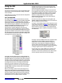
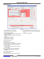
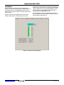
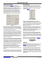
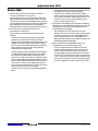
The number of cells box (Figure 34) specifies the number of cells
connected to the pack. The number in the box can be lower than
the number of cells connected to the pack. This value is a direct
representation of the number of cells, it is not the value stored in
memory. The GUI translates the number of cells value to the
proper code for the device, as specified in Table 1.
FIGURE 34. NUMBER OF CELLS BOX
When the board first powers up, the “# of Cells” is set to 3. This
causes some of the cells to show 0V in a Voltage Scan. This is
because the cells are skipped in the scan. If there are more cells
connected, change the setting, write the values to the pack, then
write the values to EEPROM.
The reason for the default value of 3 in the # of Cells box is that,
if the number in the box is greater than the number of cells
connected to the pack, when the ISL94203 first powers up it
reads a cell input as 0V. The ISL94203 thinks that this is a cell
failure, so does not complete its power up sequence. This is part
of the protection mechanisms of the part. If the value written to
the EEPROM is higher than the number of cells connected and
the device powers down, then it will not power up properly. It will
be necessary to connect the programmed number of cells (or
more) so the device powers up. Then the EEPROM value can be
reset.
For the proper connections of fewer than 8 cells, see Table 1.
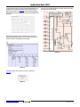
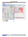
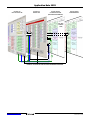
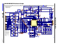
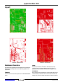
When using the evaluation board with fewer than 8 cells, connect
the unused cell inputs at the board connection. It is not
necessary to remove any components on the board (see
Figure 55 on page 31).
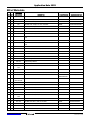
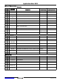
TABLE 1. ISL94203 CELL CONFIGURATION
CELLS VALUE
NUMBER OF CELLS
10000011
3 Cells connected,
C1, C2, C8
11000011
4 Cells connected,
C1, C2, C7, C8
11000111
5 Cells connected,
C1, C2, C3, C7, C8
11100111
6 Cells connected,
C1, C2, C3, C6, C7, C8
11101111
7 Cells connected,
C1, C2, C3, C4, C6, C7, C8
11111111
8 Cells connected,
All cells connected
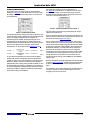
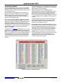
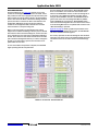
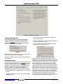
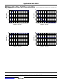
FIGURE 35. NUMBER OF CELLS BOX
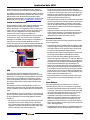
The CB lower limit and CB upper limit define the boundaries of
the cell voltage operation (except in EOC balancing). If ALL cell
voltages exceed the limits, then balancing stops. Balancing starts
again when ALL cell voltages drop back within the specified
limits plus a hysteresis. For example, if the CB upper limit is set
to 4.0V, then balancing stops when all cell voltages exceed 4.0V.
Balancing resumes when all cell voltages drop below 3.883V.
CB Max Delta specifies the maximum difference between the
CELLMAX and CELLMIN values. When this happens, it implies
that there is something wrong with the cells or connections.
When cell voltages exceed the CB Max Delta limits, the CELLF
flag is set. This can cause the PSD pin to active (optional) which
can shut down the pack. The CELLF indication also starts the
open wire detection operation.
The CB over- and under-temperature settings specify the
temperature range over which the cell balance operates. If the
external temperature sensors show that the temperature is out
of bounds, then cell balance stops.
The CBON and CBOFF times specify how long the cell balance is
on and off. These timers are mainly used for thermal control to
manage the heat dissipated by the cell balance resistors.
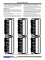
TEMPERATURE LIMITS
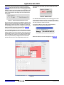
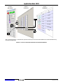
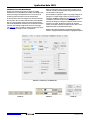
On the lower right of the Pack Settings tab are the pack
temperature limit settings. There are temperature limits for
charge and discharge as well as temperature recovery levels for
each. These limits refer to the ADC converted value of the
temperature sensor inputs, so they are affected by the TGAIN bit.
The GUI limits values in these locations from 0 to 1.8V (voltage
setting) or -40°C to +125°C (temperature setting).
NOTE: Only these combinations are acceptable. Any other combination
will prevent any FET from turning on.
CELL BALANCE LIMITS
The next box to the right (Figure 35) contains the settings for cell
balancing. The voltage limits that can be set in the GUI are fixed
at 0 and 4.8V. There are no limits to the temperature settings.
The temperature values are limited by the GUI from 0 to 1.8V
(voltage setting) or -40°C to +125°C (temperature setting).
Submit Document Feedback
21
FIGURE 36. PACK TEMPERATURE LIMIT SETTINGS
AN1952.2
December 4, 2015