1
Dr. Dobb's | Driving Design with Use Cases | December 01, 2000
1 of 2
http://www.drdobbs.com/article/print?articleId=184414677&siteSectio...
Driving Design with Use Cases
December 01, 2000
URL:http://www.drdobbs.com/driving-design-with-use-cases/184414677
We need to see more use case and Unified Modeling Language examples" is a demand we hear fairly often these days. Although we present a fairly
extensive example in our first book, Use Case Driven Object Modeling with UML (Addison-Wesley, 1999), we recently convinced Addison-Wesley to let
us produce a companion workbook, in which we will dissect the design of an Internet bookstore, step-by-step, in great detail. This will involve showing
many common mistakes, and then showing the model with its mistakes corrected.
This article is the first in a series of five that will provide a prepublication look at the annotated example from the workbook (to be called Applied Use Case
Driven Object Modeling, conveniently enough) as it evolves. We'll be following the process detailed in our book (also known as the ICONIX process),
which sits somewhere between the very large Rational Unified Process (RUP) and the very small Extreme Programming (XP) approach.
The ICONIX process is use case driven, like RUP, but lacks a lot of the overhead that RUP brings to the table. It's also relatively small and tight, like XP,
but it doesn't discard analysis and design like XP does. This process also makes streamlined use of UML while keeping a sharp focus on the traceability of
requirements. And, the process stays true to Jacobson's original vision of what "use case driven" means, in that it results in concrete, specific, readily
understandable use cases that a project team can actually use to drive the development effort.
Each of the articles that follow this one will address an essential aspect of the process by focusing on one of the four critical diagrams used in the Iconix
process. These four articles will have the same basic look and feel, with these shared elements:
A "top 10" list that describes modeling errors to avoid.
A diagram that shows two or three violations of these top 10 rules, as committed by students in classes that we've taught.
Another diagram that shows corrections of the erroneous material.
Best of Breed
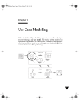
Figure 1 shows the "big picture" for the process. The diagram portrays the essence of a streamlined approach to software development that includes a
minimal set of UML diagrams and some valuable techniques that take you from use cases to code quickly and efficiently. The approach is flexible and
open; you can always select from the other aspects of UML to supplement the basic materials.
Figure 1. The "Big Picture" for Use Case Driven Object Modeling
The diagram portrays the essence of a streamlined approach to software development that
includes a minimal set of UML diagrams and some valuable techniques that take you from use
cases to code quickly and efficiently.
9/24/2014 5:12 PM
Dr. Dobb's | Driving Design with Use Cases | December 01, 2000
2 of 2
http://www.drdobbs.com/article/print?articleId=184414677&siteSectio...
The second article will discuss domain modeling. This is the task of discovering classes that represent the things and concepts related to the problem that a
system is being designed to solve. We'll describe how the domain model serves as a glossary of terms that people can use in writing use cases.
Domain modeling involves working outward from the data requirements to build a static model of the problem domain relevant to the proposed system.
We'll point out how the approach emphasizes domain modeling more than RUP, and certainly more than XP.
The third article will discuss how to write use cases that detail the scenarios that the users will be performing. We'll describe how to write complete and
unambiguous use cases that describe individual aspects of system usage without presuming any specific design or implementation.
Use case modeling involves working inward from the user requirements to start building a dynamic model of the solution space for the proposed system.
We'll talk about how use cases, by extension, drive the entire development effort.
The Forgotten Diagram
The fourth article in the series will discuss robustness analysis, a practice that originated with Ivar Jacobson but was dropped from the Rational
implementation of UML. This involves analyzing the narrative text of use cases, identifying a first-guess set of objects that will participate in those use
cases, and classifying these objects based on the roles they play.
Boundary objects are what actors use in communicating with the system.
Entity objects are usually objects from the domain model.
Controllers serve as the "glue" between boundary objects and entity objects.
We'll show how robustness analysis, which serves as preliminary design within the process, provides the missing link between analysis and detailed design.
The fifth and last article will discuss interaction modeling, the phase in which people build the threads that weave their objects together and enable them to
start seeing how the new system will perform useful behavior. We'll demonstrate how to build sequence diagrams, which enable designers to perform three
key tasks:
1. Allocate behavior among boundary objects, entity objects, and controllers that will become full objects in the model.
2. Show the detailed interactions that occur over time among the objects associated with each use case.
3. Finalize the distribution of operations among classes.
We'll explain how the detailed, design-level class diagrams that result from interaction modeling represent a suitable foundation for moving into the coding
phase of a project.
We'd like to point out three significant features of this approach.
First, it's iterative and incremental. Multiple iterations occur between developing the domain model and identifying and analyzing the use cases. Other
iterations exist, as well, as the team proceeds through the life cycle. The static model gets refined incrementally during the successive iterations through the
dynamic model (composed of use cases, robustness analysis and sequence diagrams). Please note, though, that the approach doesn't require formal
milestones and lots of bookkeeping; rather, the refinement efforts result in natural milestones as the project team gains knowledge and experience.
Second, the approach offers a high degree of traceability. At every step along the way, you refer back to the requirements in some way. There is never a
point at which the process allows you to stray too far from the user's needs. Traceability also refers to the fact that you can track objects from step to step as
analysis melds into design.
Third, the approach offers streamlined usage of UML. The steps that we'll describe in the upcoming articles represent a "minimalist" approach-they
comprise the minimal set of steps that we've found to be necessary and sufficient on the road to a successful OO development project. By focusing on a
subset of the large and often unwieldy UML, a project team can also head off "analysis paralysis" at the pass.
E-Commerce Example
We'll demonstrate these aspects of the ICONIX process in the context of an on-line bookstore. The focus will be on the customer's view of the system.
Article two will describe how to build a domain model that has loosely coupled classes, each of which does one thing well.
Article three will discuss how to write small, concise use cases that capture functional requirements in terms of user actions and system responses in a way
that's easy for readers to understand at a glance.
Article four will demonstrate how to do robustness analysis in order to tighten up use cases and make it easier to head into detailed design.
Article five will explore sequence diagrams, which we'll use to allocate the behavior specified by use cases to the objects mentioned in those use cases.
See you next month.
Terms of Service | Privacy Statement | Copyright © 2014 UBM Tech, All rights reserved.
9/24/2014 5:12 PM
January 2001: Driving Design: The Problem Domain
http://www.dca.fee.unicamp.br/cursos/EA976/Referencias/sd/ddtpd.html
Driving Design: The Problem Domain
January 2001
Part two of five: Domain modeling is an essential part of the ICONIX process.
It builds the initial static portion of a model, which is essential when driving your
application design forward from use cases.
by Doug Rosenberg and Kendall Scott
Read Part 1: Driving Design with Use Cases
Welcome to the second in a series of five articles that provide a pre-publication look at the annotated example
from our forthcoming book Applied Use Case Driven Object Modeling (Addison-Wesley, 2001; tentatively
scheduled for April). We're following the process detailed in our first book, Use Case Driven Object
Modeling with UML (Addison-Wesley, 1999), as we dissect the design of an Internet bookstore.
The focus of this article is domain modeling. The term "problem domain" refers to the area that encompasses
real-world things and concepts related to the problem that the system is being designed to solve. Domain
modeling is the task of discovering "objects" (classes, actually) that represent those things and concepts.
You may wonder why we're starting a series on use case driven object modeling by writing about the
seemingly unrelated subject of domain modeling. The reason is that we write our use cases in the context of
the object model (which we'll discuss in next month's article), instead of from an abstract, pure user
viewpoint. This process allows us to connect the static and dynamic portions of the model, which is essential
if we're going to drive our application design forward from the use cases. The domain model serves as a
glossary that the writers of use cases can use in the early stages of that effort.
Within the ICONIX process, domain modeling involves working outward from the data requirements to build
a static model of the problem domain relevant to the proposed system. This inside-out approach contrasts
with the outside-in approach we take toward user requirements, which we'll describe in the third article in this
series. (The fourth article, about robustness analysis, will describe how the domain modeling and use case
development paths merge.)
Figure 1 illustrates where domain modeling
resides within the "big picture" for the
ICONIX process.
Figure 1. The "Big Picture" for Use Case Driven Object Modeling
Key Elements of Domain Modeling
The first thing you must do when building a
static model of your system is find
appropriate classes that accurately represent
the real abstractions that the problem domain
presents. If you execute this activity well,
you will not only have a solid foundation on
1 of 4
9/24/2014 5:13 PM
January 2001: Driving Design: The Problem Domain
2 of 4
http://www.dca.fee.unicamp.br/cursos/EA976/Referencias/sd/ddtpd.html
which to build the system, but also excellent
prospects for reuse by systems that will be
designed and built over time.
The best sources of classes are likely to be
the high-level problem statement, lower-level
requirements and expert knowledge of the
problem space. To get started, lay out as
many relevant statements from these areas
(and even others, such as marketing
literature) as you can find, and then circle, or
highlight, all the nouns and noun phrases. As
you work, refine the lists; gradually, nouns
and noun phrases will become objects and
attributes, while verbs and verb phrases will
become operations and associations.
The diagram portrays the essence of a streamlined approach to software
Possessives ("its," "ours" and "theirs") tend to development that includes a minimal set of UML diagrams and some
valuable techniques that take you from use cases to code quickly and
indicate that nouns should be attributes,
efficiently.
rather than objects.
Next, sift through your list of candidate classes and eliminate unnecessary items. Look for classes that are
redundant, irrelevant, incorrect or vague. Unessential classes may also represent concepts outside the scope
of the model, or represent actions even though they're phrased as nouns: For example, Order Processor
represents the nounification of the verb pharse, "process order."
You should also make some initial decisions about generalization ("kind of" or "is a" relationships among
classes) while building your class diagram(s). If you need to, and you're comfortable doing so at this stage,
generalize to more than one level of a subclass. Remember to look for kind-of statements that are true in the
real world. Domain modeling is also the appropriate area for decisions about aggregations ("part of" or "has"
relationships among classes).
Finally, much like an entity-relationship diagram (ERD), your domain model, updated to show
associations—the static relationships between pairs of classes—should be a true statement about the problem
space, independent of time (that is, static). This model serves as the foundation of your static class model.
The Top 10 Domain Modeling Errors
The flip side of the principles that we just discussed are a number of common errors that our students make
when they're doing domain modeling for their projects. Our "top 10" list follows:
10. Don't immediately assign multiplicities to associations. Make sure that every association has an explicit
multiplicity. Some associations on a class diagram represent one-to-one relationships, while others represent
one-to-many relationships. These are both called multiplicities. However, you can avoid dealing with
multiplicity altogether during domain modeling—it chews up time and can be a major cause of analysis
paralysis, which we'll signal with this symbol.
9. Don't do such an exhaustive noun and verb analysis that you pass out along the way. Kurt Derr's Applying
OMT (SIGS Books, 1995) is a good source of information about "grammatical inspection." If you follow
Derr's advice to the letter, however, you'll likely reach such an extreme level of detail, at such a low level of
abstraction, with regard to your objects, that you can't breathe. Use this technique to get your object
9/24/2014 5:13 PM
January 2001: Driving Design: The Problem Domain
3 of 4
http://www.dca.fee.unicamp.br/cursos/EA976/Referencias/sd/ddtpd.html
discovery started, but take care not to get carried away.
8. Don't assign operations to classes without exploring use cases and sequence diagrams. Take a minimalist
approach to defining operations during domain modeling. In fact, don't assign any operations to classes
during domain modeling, because there isn't enough information available with which to make good design
decisions about operations at that stage. Wait until you begin interaction modeling, before you assign
operations to classes.
7. Don't optimize your code for reusability before making sure you've satisfied the user's requirements. The
more general your objects and classes, the higher the probability that you'll be able to reuse those objects and
classes for other projects. A complete class is one that is theoretically reusable in any number of contexts.
However, in order to achieve reusability and completeness, you must consider both attributes and operations,
and we just told you why you shouldn't be assigning operations to classes during domain modeling. So don't
worry too much about making classes reusable when you're doing high-level class diagrams.
6. Don't debate whether to use aggregation or composition for each of your part-of associations. Grady
Booch's original descriptions of "has by reference" relationships morphed into aggregation within UML.
Similarly, "has by value" became a "strong" form of aggregation called "composition" within which a "piece"
class is "owned by" one larger class. Trying to differentiate between these two during a domain modeling
effort is a definite way to do some serious tail-chasing. We much prefer to focus on simple aggregation
during domain modeling. Aggregation versus composition is a detailed design issue.
5. Don't presume a specific implementation strategy without modeling the problem space. As part of the
ongoing refinement of your domain model, you should remove anything that clearly states an action rather
than a dependency or that is specifically related to implementation. Don't introduce things on your high-level
class diagrams that represent commitments to specific technologies, whether it's a relational database or a
particular kind of server. Leave implementation issues to implementation.
4. Don't use hard-to-understand names for your classes, like cPortMgrIntf, instead of intuitively obvious
ones, like PortfolioManager. Doing domain modeling up front helps everyone on the project team agree on
what classes should be called. The more obvious the class names, the easier that task will be. Save acronyms
and other kinds of abbreviations (if you insist on having them) for implementation.
3. Don't jump directly to implementation constructs such as friend relationships and parameterized classes.
UML offers lots of opportunities to add what we call "Booch stuff" to class diagrams. This includes
constructs that come more or less directly from C++, such as abstract and parameterized classes and friend
relationships. These are more relevant to the solution space than to the problem space, though, and the focus
of domain modeling should definitely be the problem space.
2. Don't create a one-for-one mapping between domain classes and relational database tables. If you're
reengineering a legacy system that uses a relational database, the tables within that database are likely to be
an excellent source of domain classes. However, be careful not to just bring them over to your static model
wholesale. Relational tables can have lots of attributes that might not belong together in the context of an
object model. You should use aggregation to factor groups of attributes into "helper" classes, which contain
attributes and operations that are relevant to more significant classes.
1. Don't perform "premature patternization," which involves building cool solutions, from patterns, that have
little or no connection to user problems. Patterns often become visible during robustness analysis. As we'll
explore in the fourth article of this series, there are two strategies, "control in the screen" and "use case
9/24/2014 5:13 PM
January 2001: Driving Design: The Problem Domain
http://www.dca.fee.unicamp.br/cursos/EA976/Referencias/sd/ddtpd.html
controller," that lend themselves to discovering patterns connected to use cases. Looking ahead to interaction
modeling, design patterns can be highly useful in the context of sequence diagrams and design-level class
diagrams. However, domain modeling is not the time to start thinking in terms of patterns.
Figure 2 shows a class diagram that violates Figure 2. A Flawed Class Diagram
five of the top 10 rules.
Did you spot the violations?
The cBinaryTree class is a
parameterized class (also known as a
template class within UML). This
violates rule number three. There is no
good reason to define an
implementation construct such as a
binary tree at this stage of modeling.
The name of the
cSessionBeanShpngCrt class indicates
This class diagram violates the third, fifth, sixth, eighth and ninth rule from
that the modeler has decided to
our top 10 list of domain modeling mistakes.
represent the concept of a shopping
cart using a session Enterprise Java Bean (EJB). This violates rule number five. Robustness analysis,
which we'll discuss in the fourth article in this series, is the appropriate stage to explore how to map
classes to Java Beans and so on.
This class also has a composition relationship with the Order class. This violates rule number six. The
modeler has committed to the idea that an order disappears when the shopping cart object to which it
belongs is destroyed. This may or not make sense in the long run, but it's certainly too soon to be
thinking along those lines.
The cLoginMgr class has an operation named verifyPassword. This violates rule number eight. It's too
early to make decisions about which operations go on which classes, and besides, chances are good that
the operation belongs on the Login Info class anyway.
The names of the two classes we just discussed should be Shopping Cart and Login Manager. The
current names both violate rule number four.
See the diagram in Figure 3 to see how the
mistakes are corrected.
Figure 3. A Corrected Class Diagram
Our next article will discuss how to write
small and concise use cases that capture
functional requirements in terms of user
actions and system responses in a way that's
easy for readers to understand at a glance.
See you then.
The rule violations found in Figure 2 are corrected here.
4 of 4
9/24/2014 5:13 PM
February 2001: Top Ten Use Case Mistakes
http://www.sdmagazine.com/print/
Top Ten Use Case Mistakes
February 2001
"Use case driven" means writing the user manual first, then writing the code. This
practice reinforces the fundamental notion that a system must conform to the
needs of the users, instead of your users conforming to the system.
by Doug Rosenberg and Kendall Scott
Read part 1: Driving Design with Use Cases
Read part 2: Driving Design: The Problem Domain
Welcome to the third in a series of five articles that provides a prepublication look at the annotated example
from the forthcoming book, Applied Use Case Driven Object Modeling (Addison-Wesley, 2001;
tentatively scheduled for April). We're following the process detailed in our first book, Use Case Driven
Object Modeling with UML (Addison-Wesley, 1999), as we dissect the design of an Internet bookstore. In
this article, we show common mistakes, and then explain how to correct them.
Within the ICONIX process, one of the early steps involves building a use case model. This model is used to
capture the user requirements of a new system (whether it's being developed from scratch or based on an
existing system) by detailing all the scenarios that users will perform. Use cases drive the dynamic model and,
by extension, the entire development effort.
Figure 1. The "Big Picture" for Use Case Driven
Object Modeling
The diagram portrays the essence of a streamlined
approach to software development that includes a
minimal set of UML diagrams and some valuable
techniques that take you from use cases to code quickly
and efficiently.
1 of 6
1/29/2004 6:24 PM
February 2001: Top Ten Use Case Mistakes
http://www.sdmagazine.com/print/
Figure 1 shows where use case modeling resides within the "big picture" of the ICONIX process.
The Key Elements
The task of building use cases for your new system is based on immediately identifying as many as you can,
and then establishing a continuous loop of writing and refining the text that describes them. Along the way,
you will discover new use cases, and also factor out commonality in usage.
You should keep one overriding principle in mind during your effort to identify use cases: They should have
strong correlations with material found in the system's user manual. The connection between each use case
and a distinct section of your user guide should be obvious. It reinforces the fundamental notion that you are
designing a system that will conform to the viewpoints of the users. It also provides a convenient summary of
what "use case driven" means: Write the user manual, then write the code. If you're reengineering a legacy
system, you can simply work backward from the user manual.
Once you have some text in place for a use case, it's time to refine it by making sure the sentences are clear
and discrete, the basic format of your text is noun-verb-noun, and the actors and potential domain objects
are easy to identify. You should also update your domain model—the subject of our previous article, "Driving
Design: The Problem Domain" (Jan. 2001)—as you discover new objects and expand your understanding of
the objects you'd previously found. And, it's important to determine all possible alternate courses of action for
each use case wherever possible, an activity which should take up the majority of the time.
You can use several mechanisms to factor out common usage, such as error handling, from sets of use cases.
This is usually effective, because breaking usage down to atomic levels will ease the analysis effort and save
you lots of time when drawing sequence diagrams. Whether you use UML's generalization and includes and
extends relationships, or OML's invokes and precedes relationships, which we recommend in our book,
your goal should be a set of small, precise, reusable use cases.
You should feel comfortable proceeding to the next phases of the development process when you've
achieved the following goals:
You've built use cases that together account for all of the desired functionality of the system.
You've produced clear and concise written descriptions of the basic course of action, along with
appropriate alternative courses of action, for each use case.
You've factored out scenarios common to more than one use case, using whichever constructs you're
most comfortable with.
The Top 10 Use Case Modeling Errors
Contrary to the principles we just discussed are a number of common errors that we have seen students
make when they're doing use case modeling on their projects for the first time. Our "top 10" list follows.
10. Don't write functional requirements instead of usage scenario text. Requirements are generally
stated in terms of what the system shall do, while usage scenarios describe actions that the users take and the
responses that the system generates. Eventually, our use case text will be used as a run-time behavioral
specification for the scenario we'll describe, and this text will sit on the left margin of a sequence diagram. We
want to be able to easily see how the system (shown with objects and messages) implements the desired
behavior, as described in the use case text. So, we need to clearly distinguish between usage descriptions
(behavior) and system requirements.
2 of 6
1/29/2004 6:24 PM
February 2001: Top Ten Use Case Mistakes
http://www.sdmagazine.com/print/
9. Don't describe attributes and methods rather than usage. Your use case text shouldn't include too
many presentation details, but it should also be relatively free of details about the fields on your screens. Field
names often match the names of attributes on your domain classes, which we discussed in January's article.
Methods shouldn't be named or described in use case text because they represent how the system will do
things, as opposed to what the system will do.
8. Don't write the use cases too tersely. When it comes to writing text for use cases, expansive is
preferable. You need to address all of the details of user actions and system responses as you move into
robustness analysis and interaction modeling, so you might as well put some of those details in your use cases.
Remember also that your use cases will serve as the foundation for your user manual. It's better to err on the
side of too much detail when it comes to user documentation.
7. Don't divorce yourself completely from the user interface. One of the fundamental notions of "use case
driven" is that the development team conforms the design of the system to the viewpoints of the users. You
can't do this without being specific as to what actions the users will perform on your screens. As we
mentioned for item number nine, you don't need to talk about fields in your use case text, and you don't want
to discuss the cosmetic appearance of your screens; however, you can let your prototypes, in whatever form
they take, do that work for you. You do need to discuss those features of the user interface that allow the
user to tell the system to do something.
6. Don't avoid explicit names for your boundary objects. Boundary objects are the objects with which
actors will interact. These frequently include windows, screens, dialogs and menus. In keeping with our theme
of including ample detail and being explicit about user navigation, we submit that it's necessary to name your
boundary objects explicitly in your use case text. It's also important to do this because you will explore the
behavior of these objects during robustness analysis (the subject of the next article in this series), and it can
only reduce ambiguity and confusion to name them early.
5. Don't write in the passive voice, using a perspective other than the user's. A use case is most
effectively written from the user's perspective as a set of present-tense verb phrases in active voice. The
tendency of engineers to use passive voice is well-established, but use cases should state the actions that the
user performs, and the system's responses to those actions. This kind of text is only effective when it's
expressed in the active voice.
4. Don't describe only user interactions; ignore system responses. The narrative of a use case should be
event- response oriented, as in, "The system does this when the user does that." The use case should capture
a good deal of what happens "under the covers" in response to what the actor is doing, whether the system
creates new objects, validates user input, generates error messages or whatever. Remember that your use
case text describes both sides of the dialog between the user and the system.
3. Don't omit text for alternative courses of action. Basic courses of action are generally easier to identify
and write text for. That doesn't mean, however, that you should put off dealing with alternative courses until,
say, detailed design. Far from it. In fact, it's been our experience that when important alternative courses of
action are not uncovered until coding and debugging, the programmer responsible for writing or fixing the
code tends to treat them in ways that are most convenient for him. Needless to say, this isn't healthy for a
project.
2. Don't focus on something other than what is "inside" a use case, such as how you get there or what
3 of 6
1/29/2004 6:24 PM
February 2001: Top Ten Use Case Mistakes
http://www.sdmagazine.com/print/
happens afterward. Several prominent authors, such as Alistair Cockburn and Larry Constantine, advocate
the use of long, complicated use case templates. Spaces for preconditions and post-conditions are generally
present on these templates. We like to think of this as the 1040 "long form" approach to use case modeling,
in comparison to the 1040EZ-like template that we advocate (two headings: Basic Course and Alternate
Course). You shouldn't insist on using long and complex use case templates just because they appeared in a
book or article.
1. Don't spend a month deciding whether to use includes or extends. In our years of teaching use case driven
development, we've yet to find a situation where we've needed more than one mechanism for factoring out
commonality. Whether you use UML's include construct, or OML's invoke and precede mechanisms, or
something else that you're comfortable with, doesn't matter; simply pick one way of doing things and stick
with it. Having two similar constructs is worse than having only one. It's just too easy to get confused—and
bogged down—when you try to use both. Don't spin your wheels.
Figure 2 shows use case text that contains violations of five of the top 10 rules.
Did you spot the violations?
Use case one is too terse. There is no reference to what kind of information the customer enters, nor
to the page he or she is looking at. The text doesn't explain what is involved in validating the data that
the customer entered. And the use case doesn't describe how the customer needs to respond to an
error condition.
Use case two doesn't have explicit names for the relevant boundary objects.
Use case three reveals how useless it can be to obsess about using a complicated use case template.
The name of the use case expresses the goal clearly enough; the content of the basic course will make
the stated precondition and postcondition redundant.
Use case four lacks alternate courses, even though it should be fairly clear from the context that some
validation needs to occur, and that there are several possible error conditions (for instance, the system
can't find the e-mail address, or the password that the customer entered doesn't match the one that is
stored).
Use case five doesn't specify how the system responds when the customer presses the update button.
Figure 3 shows the use case text with the mistakes corrected.
Our next article will demonstrate how to do robustness analysis in order to tighten up use cases and make it
easier to head into detailed design. See you next month.
Figure 2. The 1040 "Long Form" Approach to Use Cases
4 of 6
1/29/2004 6:24 PM
February 2001: Top Ten Use Case Mistakes
http://www.sdmagazine.com/print/
Use case text that contains violations of five of the top 10 rules.
[back to text]
Figure 3. The 1040EZ Approach to Use Cases
5 of 6
1/29/2004 6:24 PM
February 2001: Top Ten Use Case Mistakes
http://www.sdmagazine.com/print/
The use case text with the mistakes corrected.
[back to text]
6 of 6
1/29/2004 6:24 PM
Dr. Dobb's | Successful Robustness Analysis | March 01, 2001
1 of 4
http://www.drdobbs.com/article/print?articleId=184414712&siteSectio...
Successful Robustness Analysis
This simple and useful technique links the what of analysis to the how of design by ensuring your use case text is correct. It addresses
necessary courses of action and allows you to continue to discover objects.
March 01, 2001
URL:http://www.drdobbs.com/successful-robustness-analysis/184414712
by Kendall Scott and Doug Rosenberg
Read part 1: Driving Design with Use Cases
Read part 2: Driving Design: The Problem Domain
Read part 3: Top Ten Use Case Mistakes
Welcome to the fourth in a series of five articles that provides a pre-publication look at the annotated example from the forthcoming Applied Use Case
Driven Object Modeling. (Addison-Wesley, 2001; tentatively scheduled for June). We're following the process detailed in our first book, Use Case Driven
Object Modeling with UML (Addison-Wesley, 1999), as we dissect the design of an Internet bookstore. This article is the third one in which we show
common mistakes, and then explain how to correct them.
This article focuses on robustness analysis, which involves analyzing the narrative text of use cases and identifying a first-guess set of objects that will
participate in each use case, then classifying these objects into three types:
1. Boundary objects, which actors use in communicating with the system.
2. Entity objects, which are usually objects from the domain model (the subject of "Driving Design: The Problem Domain," Jan. 2001).
3. Control objects (which we usually call controllers because they often aren't real objects), which serve as the "glue" between boundary objects and
entity objects.Figure 1 shows the visual icons for these three types of objects.
Within the ICONIX process, this simple but highly useful technique serves as a crucial
link between analysis—the what—and design—the how, as shown in Figure 2. Figure 3
Figure 1. Visual Icons of Three Stereotypes
shows where robustness analysis resides within the "big picture" for the ICONIX process.
The Key Elements
Robustness analysis plays several essential roles within the ICONIX process. Note that
you will refine both your use case text and your static model as a result of robustness
analysis, as shown in Figure 4.
Robustness analysis provides a sanity check by helping you make sure that your use case
text is correct and that you haven't specified system behavior that is unreasonable—or
impossible—given the set of objects you have. This refinement of the use case text
changes the nature of that text from a pure user manual perspective to a usage description
in the context of the object model.
Actors use boundary objects to communicate with the system. Entity objects
are usually derived from the domain models, and control objects (also
known as controllers) serve as the glue between boundary and entity objects.
Figure 2. Purpose of Robustness Analysis
It also provides a completeness and correctness check by helping you determine if the use
cases address all necessary alternate courses of action, which we discussed in the third
article in this series, "Top Ten Use Case Mistakes" (Feb. 2001). In our experience, the time
spent drawing robustness diagrams toward this end, and also toward the end of producing
text that adheres to some well-defined guidelines, is invariably made up three- or four-fold
in time saved in drawing sequence diagrams.
Robustness analysis enables the ongoing discovery of objects; a crucial step because you
almost certainly missed some objects during domain modeling. You can also address
object naming discrepancies and conflicts before they cause serious problems. And,
robustness analysis helps you ensure that you've identified most of the major domain
classes before starting sequence diagrams.
This simple but highly useful technique serves as a crucial link between
analysis-the what-and design-the how.
Finally, robustness analysis fills the role of preliminary design, by closing the gap between
Figure 3. The "Big Picture" for Use Case Driven Object Modeling
analysis and detailed design.
Let's take a closer look at the three stereotypes that we apply to objects during robustness
analysis.
9/24/2014 5:12 PM
Dr. Dobb's | Successful Robustness Analysis | March 01, 2001
http://www.drdobbs.com/article/print?articleId=184414712&siteSectio...
Boundary objects are the objects with which the actors (for instance, the users) will be
interacting in the new system. These frequently include windows, screens, dialogs and
menus. If you have a GUI prototype in place, you can see what many of your primary
boundary objects will be, and if you follow the guidelines we gave you last month, you
can also easily pick boundary objects out of your use case text.
Entity objects often map to the database tables and files that contain the information that
needs to "outlive" use case execution. Some of your entity objects are "transient" objects,
such as search results, that "die" when the use case ends, and many of your entity objects
will come from your domain model.
Control objects (controllers) embody much of the application logic and serve as the
connecting tissue between the users and the stored data. This is where you capture
frequently changing business rules and policies, and localize changes to these objects
without disrupting your user interface or your database schema down the line. Once in a
while (perhaps 20 percent of the time), controllers are "real objects" in a design, but
controllers usually serve as placeholders to assure that you don't forget any functionality
and system behavior required by your use cases.
You perform robustness analysis for a use case by walking through the use case text, one
sentence at a time, and drawing the actors, the appropriate boundary, entity objects and
controllers, and the connections among the various elements of the diagram. You should
be able to fit the basic course and all of the alternate courses on one diagram. Four basic
rules apply:
1.
2.
3.
4.
The diagram portrays the essence of a streamlined approach to software
development that includes a minimal set of UML diagrams and some
valuable techniques that take you from use cases to code quickly and
efficiently.
Figure 4. The Essential Roles of Robustness Analysis
Actors can only talk to boundary objects.
Boundary objects can only talk to controllers and actors.
Entity objects can only talk to controllers.
Controllers can talk to boundary objects and entity objects, and to other controllers,
but not to actors
Keep in mind that both boundary objects
and entity objects are nouns, and that
Figure 5. Robustness Analysis Rules
controllers are verbs. Nouns can't talk to
other nouns, but verbs can talk to either
nouns or verbs. Figure 5 summarizes the
robustness diagram rules.
You will refine both your use case text and your static model as a result of
robustness analysis.
Anyone who reviews a robustness
diagram should be able to read a course
of action in the use case text, trace his
finger along the associations on the
diagram, and see a clear match between
text and picture. You will probably have
to rewrite your use case text as you do
Both boundary objects and entity objects are nouns, and
this, to remove ambiguity and to
explicitly reference boundary objects and controllers are verbs. Nouns can't talk to other nouns, but
verbs can talk to either nouns or verbs.
entity objects. Most people don't write
perfect use case text in the first draft.
In addition to using the results of robustness analysis to tighten up the use case text, you should also continuously refine your static model. The new objects
you discover drawing the diagrams should become part of your class diagrams when you discover them, and this is also the right time to add some key
attributes to your more significant classes.
Top 10 Robustness Analysis Errors
Many of the students we've taught make a number of errors when they're doing robustness analysis for the first time. Our "top 10" list of solutions to
common errors follows.
10. Don't violate the robustness diagram rules. These rules are in place primarily to get your text into noun-verb-noun format and to help ensure that you
don't start allocating behavior to objects before you have enough information to make good design decisions. (We'll talk more about behavior allocation in
our upcoming article on sequence diagrams.) The rules about boundary objects are in place to ensure that you explicitly specify the boundaries of the
system, outside of which reside the actors involved in your use cases.
9. Use robustness analysis to help you use a consistent format for your use case text. The boundary object-controller-entity object pattern tends to appear
on lots of robustness diagrams. This pattern closely correlates with the subject-verb-object pattern of basic English sentences. You should use robustness
analysis to make the text of your use cases stylistically consistent among themselves to the largest extent you can, which greatly improves their readability
and maintainability.
8. Include alternate courses on robustness diagrams. You need to perform robustness analysis on all of your use case text, not just the basic courses. Much
2 of 4
9/24/2014 5:12 PM
Dr. Dobb's | Successful Robustness Analysis | March 01, 2001
http://www.drdobbs.com/article/print?articleId=184414712&siteSectio...
of the interesting behavior of a system occurs in the context of alternate courses, so it's important to analyze that behavior as part of your modeling efforts.
Robustness analysis can also help you discover new alternate courses, especially when you draw controllers with labels such as Verify and Validate.
7. Use robustness analysis to ensure consistency between class names on class diagrams and in use case text. Specifying use case text in the context of the
object model is the magic formula you need to build useful sequence diagrams. By naming your boundary objects and entity objects in your use cases, you
take a healthy step toward getting your sequence diagrams off to a good start, by simply drawing those objects across the top of the sequence diagram for
each use case.
6. Don't allocate behavior to classes on your robustness diagrams. As we mentioned earlier, controllers serve as placeholders for functionality and system
behavior. You should not start assigning methods to classes on a robustness diagram, because you're not likely to have enough information. Make decisions
about behavior allocation using sequence diagrams.
5. Don't include too few or too many controllers. We like to see between two and five controllers on a robustness diagram. If you only have one controller
per use case, you're likely to have a lot of very small use cases, each of which don't really describe enough behavior. On the other hand, if you have more
than 10 controllers on one diagram, you should consider splitting your use case up into more manageable chunks.
4. Don't take too much time trying to perfect robustness diagrams. The robustness diagram serves as a "booster-stage engine" that gets the process of
driving use cases forward into an object-oriented design off the ground. Robustness analysis helps us discover objects, allocate attributes, and check the use
case text for completeness and correctness. But once we've accomplished the overall mission, we don't need to maintain the work product. It's a means to
an end, not an end in itself.
3. Don't try to do detailed design on robustness diagrams. The concept of throwaway diagrams is useful in connection with preliminary design; it's not a
useful concept when it comes to detailed design. Sequence diagrams are the appropriate place for detailed design. Robustness analysis should be a quick
pass across all of the scenarios you're going to build, in order to provide maximum value to your project. If your preliminary design takes as long as
detailed design, you'll lose the benefits of this quick sanity check.
2. Perform a visual trace between the use case text and the robustness diagram. We strongly recommend that you have a peer review for all of your use
case text and robustness diagrams, with each reviewer performing the finger trace technique that we described earlier. You should not consider your use
case done until it passes the simple visual trace test. When you've reached the point where each of your use cases pass the test, the next step-drawing
sequence diagrams-will be easier for you to perform than if you were starting from your use case text alone.
1. Update your static model. You must update your domain model before you can consider yourself done with robustness analysis and ready to move on to
interaction modeling using sequence diagrams. After all, you can't allocate behavior to classes that don't appear in your static model.
Figure 6 shows a robustness diagram that contains violations of four of the top 10 rules.
Figure 6. Incorrect Robustness Diagram
This diagram violates rules three, six, eight and 10.
Did you spot the violations?
The Home Page boundary object is talking to the Login Page boundary object and the Account Table entity object, violations of rule 10.
The Account Table object has a method assigned to it. This violates rule six.
There aren't any alternate courses (what happens if the passwords don't match, for instance?) associated with the Validate Login Info control object, a
violation of rule eight.
The Intercept Request object is a construct that belongs to detailed design. This violates rule three.
Figure 7 shows the robustness diagram with the mistakes corrected.
Figure 7. Corrected Robustness Diagram
3 of 4
9/24/2014 5:12 PM
Dr. Dobb's | Successful Robustness Analysis | March 01, 2001
4 of 4
http://www.drdobbs.com/article/print?articleId=184414712&siteSectio...
This diagram doesn't do detailed design: There is no behavior allocated to
objects and it includes alternate courses.
Our next article will demonstrate how to draw sequence diagrams, which reside at the core of detailed design within the ICONIX process. See you next
month.
Note:
denotes analysis paralysis.
Terms of Service | Privacy Statement | Copyright © 2014 UBM Tech, All rights reserved.
9/24/2014 5:12 PM
Sequence Diagrams: One Step at a Time
http://www8.tfe.umu.se/courses/systemteknik/Doit/UML/Sequence Dia...
Sequence Diagrams: One Step at a Time
April 2001
Interaction modeling allows you to lay out the detailed behavior of your objects and find
appropriate homes for attributes and operations. In this fifth installment from a
forthcoming book, you'll learn to update and expand your static model.
by Doug Rosenberg and Kendall Scott
Read part 1: Driving Design with Use Cases
Read part 2: Driving Design: The Problem Domain
Read part 3: Top Ten Use Case Mistakes
Read part 4: Successful Robustness Analysis
Welcome to the fifth in a series of articles that dissects the design of an Internet bookstore by
following the process detailed in our first book, Use Case Driven Object Modeling with UML
(Addison-Wesley, 1999). This article outlines some more common mistakes, and then explains how
to correct them. Our focus will be on performing interaction modeling using UML sequence
diagrams.
When you finish with domain modeling and robustness analysis, you will have uncovered most of
the objects in your problem space and assigned some attributes to them. You'll have also defined
static relationships among the objects on your high-level class diagram and a few dynamic
relationships on your robustness diagrams. These represent fairly broad brush strokes.
Now it's time to design how your
Figure 1. The "Big Picture" for Use Case Driven Object Modeling
software will really work (in other words,
to define the solution to your problem).
Interaction modeling is the phase where
you build the threads that weave your
objects together. Here, you'll start to see
how your new system will perform useful
behavior. Figure 1 shows where
sequence diagrams reside within the big
picture of the ICONIX process.
The Key Elements of Sequence
Diagrams
You want to achieve three primary goals
during interaction modeling.
The diagram portrays the essence of a streamlined approach to software
development that includes a minimal set of UML diagrams and some
valuable techniques that take you from use cases to code quickly and
efficiently.
First, allocate behavior among boundary, entity and control objects. During robustness analysis,
you can identify (or at least take an educated guess at) a set of objects that can accomplish the
desired behavior of your use cases. You can also break that behavior down into discrete units and
create placeholder control objects for each of those units. Then you can decide which objects are
responsible for which bits of behavior. If you don't have a good idea of what the relevant boundary,
1 of 7
9/24/2014 5:22 PM
Sequence Diagrams: One Step at a Time
http://www8.tfe.umu.se/courses/systemteknik/Doit/UML/Sequence Dia...
entity and control objects are, it's too soon to be contemplating how you'll allocate behavior. In that
case, you'll need to return to robustness analysis and make sure.
Second, show the detailed interactions that occur over time among the objects associated with
each of your use cases. Objects interact by sending messages to each other. These messages
serve as what Ivar Jacobson calls stimuli—that is, a message stimulates an object to perform some
desired action. For each unit of behavior within a use case, you must identify the necessary
messages and methods.
Third, finalize the distribution of operations among classes. You should aim to have about 75 or 80
percent of your attributes defined within the static model when you finish robustness analysis.
However, don't start defining operations during domain modeling and robustness analysis. In fact,
we recommend that you don't assign any methods at that point, because there isn't enough
information available.
Once you get to interaction modeling, however, you should have enough information. Then you can
lay out the detailed behavior of your objects—on sequence diagrams, in the context of your use
cases—and you can finalize finding appropriate homes for attributes and operations. While you do
this dynamic modeling, you'll be updating and expanding your static model, and this will solidify
your increasing knowledge of how your new system should work.
The UML's sequence diagram evolved from a combination of Jacobson's object interaction diagram
and the OMT's event trace diagram. Within the ICONIX approach, sequence diagrams represent
the major work product of design. You draw one sequence diagram that encompasses the basic
course and all alternative courses within each of your use cases. (You can use more than one page
if you need to.) The results form the core of your dynamic model—in which the system's runtime
behavior, including how it will accomplish that behavior—is defined in great detail.
There are four types of elements on a sequence diagram: the text for the use cases' course of
action, objects, messages and methods (operations).
The text for the use cases' course of action appears down the left-hand side. It's a good idea to
break up the text with white space so it's easy to see which sentence(s) correspond with each set
of elements to the right.
Objects, which you bring over directly from your robustness diagrams, are represented with two
components: the name of an object and (optionally) the class to which that object belongs. These
appear in a box at the top of the page, in the form object::class. A dotted line runs from that
box down the length of the page. You can show the robustness diagram icons above the object
boxes.
Messages are arrows between objects. A message arrow can go directly between two dotted lines,
between a line and a method rectangle, or between two method rectangles.
Methods (operations) are shown as rectangles that lie on top of the dotted lines that belong to the
objects to which they're assigned. You can use the lengths of these rectangles to reflect the focus
2 of 7
9/24/2014 5:22 PM
Sequence Diagrams: One Step at a Time
http://www8.tfe.umu.se/courses/systemteknik/Doit/UML/Sequence Dia...
of control within the sequence. A particular method is in control up to the point where its rectangle
ends.
Many people get stuck at this point in a development project. (This is especially likely if they've
skipped preliminary design.) The technique we'll describe next evolved from helping students get
"unstuck" during dozens of training workshops during the past several years.
Figure 2 shows the four steps to perform Figure 2. Four Steps for Drawing Sequence Diagrams
when drawing sequence diagrams the
ICONIX way. The steps are outlined as
follows:
Step 1. Copy the text for the given use
case from the use case specification.
Paste it onto the left margin of the page.
Doing so enables that text to serve as
an ongoing reminder of what you need
to accomplish. The result is that when
you're doing the design, the required
system behavior is always staring you in
the face. But if you don't have all the
relevant alternative courses of action
written out for each of your use cases,
you should not proceed until they're in
Pasting the use case text in the sequence diagram means user requirements
place. Otherwise, the diagrams will not are always visible when working through the design.
cover all special cases, and you won't
uncover all of the use case's behavior. This means that you won't discover all of the necessary
methods for your objects.
Step 2. Add the entity objects from the robustness diagram. Each of these objects is an instance of
a class that appears on the class diagram that represents your static model. (If you forgot to update
your static class diagrams in response to new objects discovered during robustness analysis, do it
now. These objects should have most of their attributes in place. Many of them will be serving data
to other objects.) You can expect to discover missing attributes as you work through your sequence
diagram. Be meticulous about adding them to your static model; this is likely to be your last step
before code.
Step 3. Add the boundary objects from the robustness diagram. You get a bonus point if you're
wondering why we didn't mention adding boundary objects to your domain model. The reason is
that these objects are part of the solution space; the domain model addresses the problem space.
By accounting for boundary objects on your sequence diagrams, you begin integrating the two
spaces at the start of detailed design.
If you follow the ICONIX approach, the first three steps involved in drawing sequence diagrams are
completely mechanical in nature. That can be very useful in achieving momentum as you get
3 of 7
9/24/2014 5:22 PM
Sequence Diagrams: One Step at a Time
http://www8.tfe.umu.se/courses/systemteknik/Doit/UML/Sequence Dia...
serious about your design. The fourth step, deciding which methods go on which classes, is the
essence of interaction modeling.
Step 4. Put methods on classes. This involves converting the controllers from your robustness
diagram, one at a time, to sets of methods and messages that embody the desired behavior.
(Occasionally, you may turn a controller into a real control object.) Use your robustness diagram as
a checklist to make sure you have all the required system behavior accounted for on your
sequence diagrams. Then simply check off each control object as you draw the corresponding
messages on the sequence diagrams. This will help you eliminate the insidious "oops, I forgot
about that function" error. (One controller on a robustness diagram can translate to several
methods on a sequence diagram.)
There are two basic strategies for converting controllers that appear on robustness diagrams:
control in the screen and use case controller. If you used only one strategy during your sequence
diagramming efforts, that would qualify as patternizing. The idea is that the team members
responsible for the diagrams should establish, early in the task, design standards that can be used
across all your use cases.
On the other hand, as you're diagramming the interactions among various objects, you may decide
that one or more well-established design patterns would fit in nicely. Or perhaps you might develop
new patterns to establish a standardized approach to design problems that appear across multiple
use cases. This is where much of the real object-oriented development takes place.
At this point, you've already checked the robustness diagrams against your use case text. By
checking your sequence diagrams against your robustness diagrams, you add a measure of
assurance that you're designing in response to what the user needs (in other words, meeting your
requirements).
The Top 10 Sequence Diagramming Errors
The flip side of these principles takes the form of several common errors that we've seen students
make when they're drawing sequence diagrams on their projects for the first time. Our "top 10" list
of errors follows.
10. Not doing a sequence diagram for each use case. Jacobson provided a straightforward
description of the need for interaction modeling in The Object Advantage: Business Process
Reengineering With Object Technology (Addison-Wesley, 1995): "It is only after you have drawn
interaction diagrams [called "sequence diagrams" in the UML] for all courses of events in all use
cases that you can be certain that you have found all of the roles that the system requires each
object to play and, thus, the responsibilities of each object."
9. Not putting the use case text on the sequence diagram. Writing the original requirements-level
text for the use case in the margin of the sequence diagram provides visual requirements
traceability from the design back to your user-certified requirements. The project team will have put
a lot of effort into writing the use case text, and the user community should have signed off on the
results. The diagram should match the narrative flow of the associated use case.
4 of 7
9/24/2014 5:22 PM
Sequence Diagrams: One Step at a Time
http://www8.tfe.umu.se/courses/systemteknik/Doit/UML/Sequence Dia...
8. Not identifying all of the necessary objects first on a robustness diagram. If you're having trouble
getting a sequence diagram started, you probably wrote the use case incorrectly, or you didn't
complete robustness analysis. Having proper robustness diagrams that are associated with
rigorously defined use cases makes the job significantly easier.
7. Not providing a visual trace between the use case text and the message arrows. Each sentence,
including appropriate fragments, within the use case text should have some white space around it.
Each should also line up visually with the message or set of messages that correspond with the
specified behavior. This will enable people reading the diagram to easily see how the system will
accomplish what the use case describes.
6. Not showing the plumbing; instead, keep your sequence diagram at a high level of abstraction. It
isn't necessary to show plumbing on robustness diagrams, since they reflect a preliminary design
view. However, sequence diagrams are the last stop before coding, and as such need to show the
real design in full detail.
5. Turning your sequence diagram into a flowchart instead of using it to allocate behavior among
objects. Remember that the sequence diagram is the primary vehicle for making behavior
allocation decisions. You're really using them to assign operations to your classes as you go.
Behavior allocation—deciding which operations belong to which classes—is critical in the ICONIX
approach. Decisions made during this phase of a project dictate whether the overall design is good
or bad. This is where experienced designers earn their pay.
4. Not focusing on interesting methods (real software behavior), getting distracted by getters and
setters. By exploring the system's dynamic behavior, you learn which attributes and operations are
needed in your static model's classes. To start, add attributes and methods to your classes as soon
as you decide where they go in the context of your sequence diagrams. But don't spend lots of time
adding get and set methods to your model. You should take advantage of the principle of
encapsulation: Only allow access to attributes via getters and setters.
3. Not thinking carefully about the origins of the message arrows (in other words, which object is in
control at any given time). Messages between objects invoke the operations on the associated
classes. Although it's not important to get the arrows right on robustness diagrams, it's essential to
get them right on sequence diagrams. The flow of control needs to be explicit. It should be obvious
at all times which object is in control.
2. Not following basic principles of responsibility-driven, object-oriented development when
allocating behavior by drawing message arrows. An object (and, by extension, a class) should have
a single personality. This means a class should be focused on a strongly related set of behaviors.
This parallels the well-established rules that state objects should be highly cohesive and loosely
coupled. Other principles you should focus on include reusability (the more general your objects
and classes, the more likely they are to be reusable for other projects and applicability. When you
assign methods to the objects on your sequence diagrams, always ask whether there seems to be
a good fit between method and object, and also whether the task the method performs is obviously
5 of 7
9/24/2014 5:22 PM
Sequence Diagrams: One Step at a Time
http://www8.tfe.umu.se/courses/systemteknik/Doit/UML/Sequence Dia...
relevant to the object.
1. Not updating your static model as you go by building local class diagrams for each package of
use cases. It's nice to keep a clean set of domain classes on a pure domain model diagram.
However, it's also a good idea to draw localized static class diagrams that show both solution
space objects and problem space objects. A good guideline for this is one such diagram per
package of use cases. As you come up with scaffolding and other types of infrastructure, such as
helper classes, put them on the static class diagram, as well. This is where you shift your focus
from the problem space to the solution space. It's best to use localized class diagrams—say, one
per use case package—because by this time your static model is probably too expansive to be
captured within one readable diagram. Doing this also lets you split work across teams.
A sequence diagram that contains violations of four of the top 10 rules (outlined in the following
bullet points) is shown in Figure 3. The mistakes are corrected in Figure 4.
Figure 3. Sequence Diagrams with Violations
This sequence diagram violates four of the top 10 rules. Can you spot them?
The use case text isn't spread out, so the messages are lined up with each sentence of the text. This
violates rule 7.
There is no Search Results object, which would have been identified during robustness analysis, since
we obviously aren't supposed to display the entire contents of the catalog. This violates rule 8. (Note
that the use case text is incorrect as well in this regard.)
The Search Page sends the display message, even though the diagram shows that the Catalog is in
control. This violates rule 3.
The Catalog object is invoking the displayErrorMessage method on the Search Page. This
violates rule 2. The correct approach would be for the Search Page to invoke the method on itself.
Figure 4. Corrected Sequence Diagram
6 of 7
9/24/2014 5:22 PM
Sequence Diagrams: One Step at a Time
http://www8.tfe.umu.se/courses/systemteknik/Doit/UML/Sequence Dia...
Violations to rule seven, eight, three and two have been corrected.
Stay tuned for an additonal three articles, which provide a prepublication look at the annotated
example from our forthcoming book, Applied Use Case Driven Object Modeling (Addison-Wesley,
2001; now tentatively scheduled for June).We hope the previous five articles in our modeling
tutorial have provided you with an effective process for designing e-commerce systems by
illustrating how to build a domain model with loosely coupled classes, write concise use cases, do
effective robustness analysis and create successful sequence diagrams.
Note:
7 of 7
symbolizes analysis paralysis
9/24/2014 5:22 PM