1
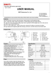
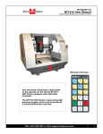
2
BluFisH HD
High Definition remote head point of view camera housing
User’s manual
Blufish 2-Inst.05
Table of contents
Features / 5
Getting Started / 6
Unpacking / 7
Features & Controls / 8
Preparing Camera Head / 9
Sealing the connector / 10
Installing Lens Port / 11-12
Installing rear cover / 12
Installation Diagram / 13
Maintenance / 14
Specifications / 15
4
Features
Blufish 2 underwater housing for the
Iconix HD HD-RH1 and Toshiba IK-HD1H POV cameras.
Features
Your Blufish 2 HD comes to you as a kit to assemble for the Iconix HD-RH1 and Toshiba
IK-HD1H POV camera head. The fully assembled system will give you access to high quality
features such as:
High Definition Images
High Performance Controls
Multi-Format Solution
High Quality construction
Corrosion resistant material
Flatport and Dome port optics
Pressure tested to 100 meters
NOTE:
Before you use the system underwater for the first time, please read these instructions
and test the system without the camera head and lens inside. This way, should an
error occur during initial O-ring installation which would cause the housing to flood,
you will not damage your camera.
Fully Assembled
5
Getting started
Getting started
What to know about the ICONIX HD-RH1 1/3” Progressive 3CCD HDTV and TOSHIBA
IK-HD1H 1/3” Interlace 3CCD Camera heads.
A revolutionary High Definition remote head point of view camera system providing a highperformance, multi-format solution in a small package.
Image Sensor
1/3-inch Progressive CCD
Image Sensor
3CCD 1/3-inch Interlace
Optical System
1/3-inch 3-CCD Prism
Output Resolution
1920(H) x 1080 (V)
1080i @ 60 Hz
Digital HD-SDI (SMPTE 292M)
Analog RGB or Y/Pb/Pr
Multi-Format
720p @ 24,25,30,50 and 60 Hz
1080i @ 50 & 60 Hz
1080p @ 24, 25, 30, 50 and 60 Hz
700 Lines (720p), 900 Lines (1080i/p)
SDI, DVI-D, and Analog Outputs
14-Bit Quantization
Electronic Shutter and Enhancement
Programmable Gamma Function
Genlock and Remote Control
Sensitivity
F6.8 standard (2000 Lux)
Minimum illumination
13 lux (F2.2, Sensitivity + 18dB)
Lens mount
G-Mount
Lens mount
G-Mount
6
Unpacking
Unpacking
Thank you for buying the Blufish 2 HD. This fully integrated system will provide you with all
the necessary features for High Definition underwater POV imaging.
Your purchase of the Blufish 2 HD comes with a 90 day warranty on parts and workmanship.
While precautions have been taken on the packaging and the shipping, some damage may
have occurred during shipping. We suggest you inspect your Blufish 2 HD package and
the individual parts in order to see if any damage has occurred or if any parts are missing.
If the external packaging appears to be damaged, we suggest you contact the shipping
company directly for coverage.
When unpacking your system, you will find the following:
- Blufish 2 HD Aluminum Housing
- Flatport Lens asembly
- Dome port assembly
- 0.235” Dia. Cable Gland
(Standard Iconix & Toshiba cable assembled with cable sample)
- Rear Bulkhead
- Rear bulkhead lock
- Toshiba Adaptor
- Iris Lever
- Iris Lever spare screw
- Tools for O-rings, Glass lock and dome lock
- O-ring lube
- Allen Key
- Extra O-rings
- #013 (2)
- #107 (1)
- #204 (1)
- 40mm x 2.5mm (2)
- Extra 0.250” Dia. Cable Gland (Toshiba cable)
- Extra 0.320” Dia. Cable Gland (Oversized Iconix cable)
7
Features & Controls
Features & Controls
2
1
7
6
5
4
3
1 - Dome port
2 - Mounting shoe
3 - Flatport
4 - Locking knob
5 - Blufish 2 Body
6 - Rear cover assembly
7 - Video cable
8
Preparing Camera Head
Preparing the Camera Head
Whether you are using the Fuji 2.8mm lens or the Fuji 4mm lens, the camera head preparation will be the same. The operation has to be done on the lens itself to adapt it to the
Blufish 2 lens adaptor. If the threaded mounting block is attached to the camera head, it
will have to be removed, as the camera head will not fit into the housing with it on. Same
process applies to the Toshiba camera head.
1. First, take your accessory lens (Fuji
2.8mm or 4mm) and securely screw it on
the camera head.
2. Identify the philips head screw near the
aperture values and unscrew it from the
lens. Keep it close for use on step 3. A
spare screw is included in your kit in case
you lose one.
3. Place the Iris Lever as shown and secure
it into place by screwing the philips head
screw back into place. The bushing should
be steady and solid. Do not over tighten the
screw. This may cause damage to the lens.
By now, you should have your camera head
all set for the final assembly. Leave the
cover on in order to protect the lens.
4. Make sure that you have the right adaptor installed inside the housing. The Iconix
adaptor comes installed by default. To
change it simply remove the socket head
cap screws (as shown) and replace the
adaptor with the right one. Then lock it back
into place with the 2 screws.
Adaptor
See page #15 for a real size graphic of
the 2 different adaptors.
Screws
9
Sealing Connector
Sealing the connector
NOTE: Same process applies to
the Toshiba cable and connector.
ASL assumes that you already have your
LEMO Connector in hand before you start
assembling the unit. Make sure when you
prepare your cable that the cable diameter
is around .215 inches or else the system will
not seal correctly.
1.
NOTE: Your Blufish 2 HD Housing was
shipped to you with a short piece of cable
showing the order of assembly. Pay attention to this assembly as you take it apart so
you’ll be familiar with putting it together with
your 18-pin LEMO connector.
1. First, insert the 2 rings, as shown, onto the
LEMO cable. It is imperative that the smaller
ring is inserted before going to step #2.
2.
2. Prepare all the sealing sleeve parts so
they line up as shown here. Insert the o-rings
on the cable in the same order that you see
in the diagram.
NOTE: O-rings #3 & #4 may be difficult to
install on the cable. Use the o-ring tool to
roll it over the connector. See image beside.
Apply a light amount of o-ring lube (supplied)
to the tool and the o-rings.
3.
3. Respectively assemble the two pieces
#2 and the two #6 as shown in the diagram.
Hold them together by installing o-rings #1
& #5. Make sure that the configuration is
exactly as shown. This way, you guarantee
a perfect seal to your cable. Finally, push #2
and #6 together.
10
Installing lens port
Installing lens port
1. Locate the notch that is machined on the
front lens port. Slide the camera lens into
the lens port and line up the Iris lever with
the notch so the camera lens sits properly
in the port. At the same time, inspect the orings on the lens port in order to see if there
is dirt or debris. If any, gently wipe it off with
your finger or a lint free tissue. Add some
silicone grease (provided) if necessary.
2. Pass the connector through the rear bulkhead, then through the main body. Leave
enough loose cable so you can handle the
connector easily. The back pre-assembly
should look like the image beside. Refer to
installation Diagram on page 13.
3. Once the camera lens is securely installed in the port, push them into the main
body until it rests against the main body.
You may feel a bit of friction while inserting
the port. This is due to the o-rings creating
a correct seal.
Locking knob
Note: you have to loosen the locking knob
in order to clear the space for the port to
go in correctly. Also, make sure that when
inserting the camera head into the main
body that both the camera and main body
inside profile mate correctly. This way, you
assure a perfect fit.
4. Finally, lock the lens port onto the main
body by screwing in the thumbscrew
located on the front part of the port. Once
completed, you may try to adjust / turn the
iris dial. The dial will turn smoothly on the
port and will change the camera lens’ iris
value.
Locking knob
11
Installing rear cover
Installing rear cover
1. First, inspect all the o-rings to detect
any dirt or debris. Clean them if necessary.
Then insert the rear cover into the main
body. Lock it into place using the bigger
locking ring.
2. Once the rear cover is installed, slide the
sealing sleeve assembly into the rear cover.
The rear flange sits on the rear edge of the
cover. Make sure that the sleeve assembly
is securely installed and lock it into place by
screwing the smaller locking ring onto the
cover.
About the BLuFISH 2 cable seal assemblies.
Due to various cable sizes from the camera
manufacturers, we have a standard cable
seal assembly that comes assembled with
the purchase of the Housing and two other
cable seal assemblies that have been
packed separately as accessories.
Iconix & Toshiba
0.215 dia.
Standard Cable Seal Assembly (blue)
– This comes attached to the Housing and
is for the original Iconix cable and for most
other Toshiba cables smaller than 30m
in length. Please check that the cable is
within .216 inches and .260 inches in OD.
Toshiba
0.250 dia.
Two additional accessories:
Black Cable Seal Assembly - This is
for the Toshiba cables that are 6.3mm to
6.9mm in thickness.
Iconix
0.320 dia.
Clear Cable Seal Assembly – This is for
the Iconix High Performance cables that are
.320 and .307 in OD. Part # 205014 p/n
90253 Rev. A & B
12
Flat port (Dome port)
Camera
Cable + Connector
Main Body
Rear Cover
13
Cable seal lock
Cable seal
Rear Cover Lock
1. In this order, pass the cable through the rear cover lock, the cable seal lock, the rear cover and then the
main body so the connector extends out of the housing from the front.
2. Plug the connector into the camera
3. Slide the camera + lens assy in the housing from the front in order to line up with the black adaptor located
inside the housing. Note that the Toshiba will sit on the shoulder while the Iconix will go through the collar.
4. Install the rear connector seal.
5. Install the front ports by lining up the iris.
6. Close the rear cover.
Installation diagram (Quick and easy recap for the housing assembly)
Installation Diagram
Maintenance
Maintenance
Keeping your system clean and preventing it from any damage will extend its lifetime and
performance. This section will tell you how to maintain your system. Please refer to the
instructional video and/or contact ASL for more info.
While assembling the unit
Inspect all the o-rings to detect any dirt or debris. If any, wipe them off with your finger or
a lint free cloth. Gently lubricate them. Do not over lubricate, as this could attract more
dirt and debris. It is good to sometimes remove the o-rings from their location and make
an overall inspection. When replacing them on the unit, do not overstretch them so that
they will keep their properties. If you use the system quite often in salt water and/or hostile
environment, we suggest that you send your system for an overall service every year. Having the o-rings serviced once in a while will extend their lifetime and their performance. An
o-ring that has never been serviced could lose its round profile, become dry and lose its
properties.
After Every Dive
Rinse the unit in fresh water for at least 10 minutes after every dive. If you can leave it
in fresh water for longer, please do so. This will prevent salt and sand to build up on and
between the pieces. Use a clean towel to remove the excess water and completely dry the
unit.
Storage
We suggest that you always keep your system in a dry and clean environment. Avoid leaving the unit near high sources of heat or cold since condensation may build up inside and
damage the camera head.
14
Maintenance
Replacing Flat port Glass
Tool
If your flat port glass gets damaged or
scratched, it is imperative to change it before damage occurs to your system or your
footage. To do so, we supplied you with a
tool that will unscrew the ring that retains
the glass.
First take the flat port off the main body
Use the tool by lining up the 2 pins with the
indents on the ring and unscrew it counterclockwise. To remove the glass, push on it
from the inside of the port. Be careful, the
glass piece could pop out. Always do it by
securing it with your hand or a towel.
Inspect the o-rings for dirt and damage.
If you feel that there is something wrong
we suggest that you replace it with the
ones supplied with the new glass. Stretch
the side o-ring a little bit so it matches the
external diameter of the groove. When this
o-ring is in place, lightly lubricate it before
installing the new glass.
Glass
Take the new glass out of the bag by holding it from the side. Then push it in using a
dry and harsh free cloth untill it sits securely
on the bottom o-ring. Never put your finger
on the visible part, it can leave a finger
print.
O-ring
Finally, screw the ring back on the port using the tool supplied. Tighten it until you see
an even seal on the bottom o-ring.
Replacing Dome
In order to replace the dome on your dome
port, repeat the procedure as for replacing
the flat port glass but using specific o-rings
and tools. Remove the shade prior to doing
the switch.
15
Specifications
Specifications
All pieces are corrosion resistant Aluminum Alloy and Stainless Steel.
Length (excluding cable): 9.85 inches
Max Width: 4.50 inches
Max Height: 4.50 inches
Weight:
With Dome Port : 852g (1lb 14oz)
With Flat Port : 661g (1lb 7oz)
In Sea water including camera head / Dome port : 274g (0.604 lbs)
In Fresh water including camera head / Dome port : 290g (0.639 lbs)
Adaptors
TOSHIBA
ICONIX
16
Warranty
Warranty
All manufactured parts of your Blufish 2 HD Housing are fully covered for defects in manufacture up to 90 days under normal use. The warranty will automatically become void if the
equipment has been mishandled, abused or modified in any way. Scratches or damages to
the dome port or flatport are not covered under this warranty. ASL Productions, Inc. is not
responsible for ANY damage to any cameras placed inside the Blufish 2 HD Housing.
These warranties extend only to the original purchaser through ASL Productions, Inc. or an
authorized dealer.
The expressed warranty set forth herein is in lieu of all other warranties expressed or implied, including without limitation any warranties of merchantability or fitness for a particular
purpose, and all such warranties are hereby disclaimed and excluded by the manufacturer. Repair or replacement of any defective part of the Housing is the sole and exclusive
remedy provided hereunder. ASL Productions, Inc. will not be liable for any further loss,
damages, or expenses, including incidental or consequential damages directly or indirectly
arising from the sale or use of this product.
Before returning your Blufish 2 HD Housing for care, please call or e-mail our service
department for an RMA# (Return Merchandise Authorization). Ship your product prepaid
freight with the return number printed on the outside of the box. It is recommended that
you keep your shipper’s tracking number until the product is returned to you.
Caution: Do not ship your camera inside any housing. Shipping companies may drop
your system from up to three feet which could damage your camera.
RETURN POLICY: Returns will be accepted within 30 days of purchase date as long as
the item has not been used. There will be a 15% restocking fee for returned items. Please
call or email for instructions before shipping back your item.
17
Air Sea Land Gear Inc.
19-69 Steinway Street
Astoria, New York 11105-1108
1 888-ASL-LENS - Sales and Marketing
718-626-2646 - Sales and Marketing
718-626-1493 - Fax
[email protected]
www.airsealand.com