1
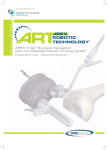
OpenSAM
Open Source Camera Stabilizer
using Additive Manufacturing
by
User Manual 1.1
May, 2015
OpenSAM user manual
Version 1.1
Disclaimers and warnings
3
j
Introduction
6
i
Diagram
7
v
Parts
8
4
Assembly
14
Q
Setup BaseCam Controller
16
ß
2
1 Disclaimers and warnings
Pleases read this manual and disclaimer carefully before using this product. By using
this product, you agree that you are responsible for your own conduct and any content
created while using this product, and for any consequences thereof. You agree to use
this product only for purposes that are proper and in accordance with local regulations,
terms and any applicable policies and guidelines.
As OHM has no control over use, setup, final assembly, modification or misuse, no
liability shall be assumed or accepted for any resulting damage or injury. By the using,
setting up, or assembling of the product, the user accept all resulting liability. OHM
assumes no liability for damages or injuries incurred directly or indirectly from the use
of this product.
OHM and OpenSAM are not registered trademarks of OHM. This product and manual is not copyrighted by OHM and may be reproduced in any form without written
consent or authorization by OHM. All names of products, brands, etc., appearing in this
manual are trademarks or registered trademarks of their respective owner companies.
1.1.
Using Lithium Polymer (LiPo) Batteries
Using the OpenSAM requires the use of an external LiPo battery, which can be extremely hazardous if handled incorrectly. General care should be followed when using
LiPo batteries:
1. Always use the correct charger when charging the battery.
2. Batteries are normally designed to stop charging when full, however it is good
practice to monitor their charging progress and disconnect them from the charger
once they are fully charged.
3. Do not charge the battery near flammable materials or on flammable surfaces such
as carpet or wood.
4. Never use or charge a swollen, leaking or otherwise damaged battery.
5. Keep both the battery and the charger dry at all times.
6. Do not expose the battery to extreme temperatures.
7. Keep batteries away from strong electrostatic or electromagnetic interferences.
8. Do not place the battery in a microwave oven.
3
j
OpenSAM user manual
1.2.
1 Disclaimers and warnings
Using the manual
2.1 Updates
For the most up-to-date version of this manual, visit the official OpenSAM website or
its associated GitHub page.
http://www.opensam.net/
https://github.com/OpenSAMOfficial/OpenSAM
2.2 Legend
1.3.
Tips
Warning
i
j
Open-Source Hardware License
Copyright OHM 2015 - Oliver Topp, Henning Si Høj, Mathias Grelck Johnsen,
Technical University of Denmark, DTU.
This documentation describes Open Hardware and is licensed under the Creative
Commons Attribution-ShareAlike 4.0 International License, CC-BY-SA1 .
You may redistribute and modify this documentation under the terms of the license.
This documentation is distributed WITHOUT ANY EXPRESS OR IMPLIED WARRANTY,
INCLUDING OF MERCHANTABILITY, SATISFACTORY QUALITY AND FITNESS
FOR A PARTICULAR PURPOSE.
You are free to:
• Share – copy and redistribute the material in any medium or format
• Adapt – remix, transform, and build upon the material for any purpose, even
commercially.
• The licensor cannot revoke these freedoms as long as you follow the license terms.
Under the following terms:
• Attribution – You must give appropriate credit, provide a link to the license, and
indicate if changes were made. You may do so in any reasonable manner, but not
in any way that suggests the licensor endorses you or your use.
• ShareAlike – If you remix, transform, or build upon the material, you must distribute your contributions under the same license as the original.
1 http://creativecommons.org/licenses/by-sa/4.0/
4
j
OpenSAM user manual
1 Disclaimers and warnings
• No additional restrictions – You may not apply legal terms or technological measures that legally restrict others from doing anything the license permits.
j
5
2 Introduction
The OpenSAM by OHM is developed for filmmaking amateurs and professionals. The
technology used allows a broad spectrum of cameras of varying sizes and weights to
be stabilized. The unique use of 3D printing technology for the custom parts allows
easy reproduction and any design changes can easily be implemented. The 3D prints
are also lightweight and allow for a convenient use. No specialized 3D printers are
needed. All parts were printed using Ultimaker Original 3D Printers or Bq Witbox 3D
Printers and their files have been made available under an open source license.
The brushless gimbal stabilization system works on three brushless motors moving
on the axes. One 8-bit brushless gimbal controller (BGC), an expansion card and an
IMU (Inertial Measurement Unit) is all the electronics needed for assembly.
6
i
3 Diagram
v
[1]
[2]
[3]
[4]
[5]
[6]
[7]
[8]
[9]
Brushless Gimbal Motor (x3)
Yaw joint
Joystick case (contains joystick)
Grip arm left
Grip arm right
Handle (x2)
Bracket L
Bracket U Bottom
Bracket U Top
[10] Grip arm one-hand (Optional)
[11] Handle (Optional)
[12] Suggested mounting place for battery
[13] (Back side) Suggested mounting
place for yaw case
[14] (Back side) Suggested mounting
place for main case
[15] Mounting place for IMU
7
4 Parts
The following is a comprehensive parts list and should be used as both documentation
of the individual parts, but it also serves as a printing and buying reference. We do not
favor or represent anybody but ourselves, so prices and links to reseller are only meant
as a guideline. The design being open-source, you can easily swap out parts and adapt
the design to fit your requirements.
4.1.
3D printed parts
All 3D printed parts have been designed using SolidWorks by Dassault Systems and
printed on PLA using Ultimaker Original 3D Printers and Bq Witbox 3D Printers, where
the Witbox was used for the larger parts that physically could not fit the Ultimaker. Unless otherwise stated, parts were printed using a Layer height of 0.2mm, Shell thickness
of 0.8mm, Bottom/Top thickness of 1.6mm and a varying Fill density between 20-50%.
Settings may vary depending on your specific printer setup.
1.1 Yaw joint (×1)
The yaw joint acts as a joint between the grip arm and
the top U bracket. It is designed so the weight of the
gimbal compresses the yaw motor instead of pulling it
apart.
i
Print laying down and with a vertical O-profile. No support
material.
1.2 Joystick case (×1)
The joystick case is designed to contain the joystick and fit the
construction.
i
Print in two separate parts with the flattest side facing down.
Support material touching buildplate.
8
4
OpenSAM user manual
4 Parts
1.3 Grip arm left (×1) and right (×1)
The grip arm attaches to the yaw joint and is divided in two
parts.
i
Print in two separate parts with the flattest side facing down.
Support material touching buildplate.
1.4 Handle (×3)
Two handles attach to the grip arm to allow holding the gimbal
with two hands.
A third handle can be attached to the optional one-hand grip
arm to allow for one handed handling.
i
Print upright, to make for a good screw hole in the middle. No
support material.
1.5 Bracket L ×3
The L bracket is the main mounting point for the camera.
As such, it needs to be especially rigid, which is why it is the
most robustly designed part.
The L bracket is attached to the bottom U bracket through the
roll motor.
i
Print on its side with a vertical L-profile. No support material.
1.6 Bracket U Bottom ×3
The bottom U bracket is attached to the top U bracket through
the pitch motor. On its back side, the main electronics board
can be mounted.
i
Print with a vertical U profile. No support material.
1.7 Bracket U Top ×3
The top U bracket is attached to the yaw joint through the yaw
motor.
i
Print with a vertical U profile. No support material.
9
4
OpenSAM user manual
4 Parts
1.8 Grip arm one-hand ×3
The one-hand grip arm is mounted between the yaw joint and
the grip arm and allows for one-handed operation.
i
Print either pointing upwards with no support material or horizontally positioned to make for at stronger part with support
material touching buildplate.
1.9 Case for simpleBCG 8-bit main board (×3)
The case is used to mount and secure the AlexMos simpleBCG 8-bit controller mainboard.
This design is easily reconfigured in SolidWorks to match other board designs.
i
Print bottom and top parts separately lying flat. No support
material.
1.10 Case for simpleBCG yaw extension board (×3)
The case is used to mount and secure the AlexMos SimpleBCG
yaw extension board.
This design is easily reconfigured in SolidWorks to match
other board designs.
i
Print bottom and top parts seperately laying flat. No support
material.
4.2.
Third party electronics
The following third party parts are required to stabilize the system. The specific chosen
parts are guidelines and can be replaced with similar parts.
2.1 BaseCam SimpleBGC 8-bit Set (×1)
Our choice of electronics is the BaseCam SimpleBCG 8-bit.
Electronics are required to control the three brushless motors.
An IMU (inertial measurement unit) sensor provides the main
board with feedback on the cameras inertial state. Specifically
it contains a gyroscope, accelerometer and magnetometer.
10
4
OpenSAM user manual
4 Parts
For this implementation, the BaseCam SimpleBGC 8-bit controller set 1 is used, consisting of a main board, a yaw extension
board and an Inertial Measurement Unit (IMU).
i
Practically, the BaseCam SimpleBGC 32-bit, STorM32 or any other electronics for controlling the motors can be used, but the main and yaw cases need to be adapted to fit
the boards specifications.
2.2 Brushless gimbal motors (×3)
The motors used are type BGM4108 brushless gimbal motors by WST 2 . Other manufacturers of the BGM4108 include RCTimer and DYS. For the smoothest operation, select motors with many poles (> 14) and many turns (>
100).
i
Practically, any suitable motor can be used, but screw holes
need to be adapted to fit the motors specifications. Also, the motors should have a
sufficient number of poles for fine adjustments.
2.3 Battery (×1)
A 12V ∼4000mAh Lithium Polymer (LiPo) battery was used to
power the motors and electronics. 3 This is sufficient to power
OpenSAM for more than 3 hours.
i
Practically, any 8-18V battery can be used, but care should be
taken on the current it can deliver and the capacity it stores.
Size and weight may also be significant factors. Current consumption is estimated to peak at 2A.
j
Make sure to connect the battery with the correct polarity!
2.4 Joystick with button (×1)
1 http://www.basecamelectronics.com/simplebgc/
2 http://www.ebay.com/itm/WST-Brushless-Gimbal-Motor-BGM4108-130T-for-Camera-Mount-FPV-PTZ-/
281343734210?pt=LH_DefaultDomain_0&hash=item418164b1c2
3 http://www.banggood.com/DC12V-9800mAh-Super-Rechargeable-Protable-Lithium-Battery-EU-Plug-p-963254.
html
11
4
OpenSAM user manual
4 Parts
The joystick allows user input to the controller to adjust the angles of the camera. It also contains a button which we choose
to use to calibrate the IMU, stop the motors and reset the controller. For a guide on how to setup the Arduino compatible PS2
joystick we used 4 see the configuration chapter of this manual.
i
Practically any joystick can be used, but compatibility to the
electronics need to be insured and the joystick case needs to be
adapted to fit the joysticks specifications.
4.3.
Generic parts
The used brushless gimbal motors and electronics for this project included cables for
connecting these and they are thus not listed here. The motors also came with screws
inclusive, these were however not long enough for this application.
3.1 M2.5 Screws (×9)
M2.5 screws are needed to attach the fixed part of gimbal motors to the system.
6x15mm and 3x25mm M2.5 screws are used if using the optional one-handed grip arm.
9x15mm M2.5 screws are used if not using the one-handed
grip arm.
3.2 M3 Screws (×14) and M3 nuts (×2)
12x15mm M3 screws are used for attaching the moving part of
the motors to the system.
2x15mm M3 screws combined with 2xM3 nuts are used to attach the left and the right parts of the grip arm.
i
For the nuts, it is recommended to use locking nuts (locknuts).
3.3 M4 Screws (×3) and M4 nuts (×3)
1x20mm M4 screws (or longer) and 1xM4 nut (loose) are used
for attaching the top U bracket to the bottom U bracket on the
side opposing the pitch motor.
4 http://www.banggood.com/PS2-Game-Joystick-Module-For-Arduino-p-76465.html
12
4
OpenSAM user manual
4 Parts
2x20mm M4 screws (or longer) and 2xM4 nuts are used for
attaching the grip arm to the top U bracket.
i
For the nuts, it is recommended to use locking nuts (locknuts).
3.4 Wood Screws (×2 + ×2)
The wood screws screw into the handles. Their length is stated
approximately.
2x80mm with a diameter of ca. 4mm are used to fixate the
outer handles.
2x40mm also with a diameter of ca. 4mm are used for the
optional one-handed grip arm.
3.5 Camera mounting screw (×1)
The standard camera mounting screw thread size is per ISO
1222:2010 1/4-20 UNC. Optimally use a thumbscrew. Also, ensure sufficient length of the screw, at least 30mm.
3.6 Reattachable fasteners (ca. 40 cm)
To mount the battery and electronic boxes to the system, we
used reattachable Dual lock fasteners for easy attachment and
removal of the parts. Approximately 40cm were used. 5
Any adhesive could also be used, but this would compromise
on the convenience.
3.7 Cable extensions (optional)
The provided cables for the electronics was a little bit short for
optimal cable management and were extended using generic
cables, a soldering iron and heat shrink tubes.
5 http://solutions.3m.com/wps/portal/3M/en_US/Adhesives/Tapes/Brands/
Dual-Lock-Reclosable-Fasteners/
13
4
5 Assembly
5.1.
Guide
Step 1
Part [15] is mounted underneath part [7] using two 4.5mm bolts and nuts.
Step 2
A motor (part [1]) is attached on the back of part [7] using four M3 bolts. Choose
the holes on part [7] so that when a camera is mounted in one of the two bottom
holes, the cameras center of mass will align with the motors rotational axis.
Step 3
Mount part [8] on the motor (part [1]) using three M2.5 bolts.
Step 4 The case of the BaseCam main board is placed at position [14] at the back of part
[8] using a reattachable fastener of your choice.
Step 5
The BaseCam main board is mounted into the case.
Step 6
Put a new motor on part [8] using four M3 bolts.
Step 7
Part [9] is put through part [2] and attached to part [8] using a 4.5mm screw in
one side, and three M2.5 bolts on the motor (part [1])
Step 8
Put part [4] and part [5] together using M3 bolts and nuts, to assemble the handlebar.
Step 9
Mount the last motor (part [1]) on the handlebar using three 2.5mm bolts. If the
onehanded grip (part [10]) is used, it needs to be mounted in between the handlebar and the new motor.
Step 10
Put the handlebar through part [2] and mounted to the upper motor using four
M3 bolts.
14
Q
OpenSAM user manual
5 Assembly
Step 11
Use two M4 bolts and nuts to fasten and position the cameras center of mass so it
aligns. with the motors rotational axis.
Step 12
Mount both parts [6] to the handlebar using two long (approx. 80mm length)
woodscrews.
Step 13
Put the joystick into part [3] and mount it to the right part [6] using a tie-wrap.
Wire the joystick by connecting the onboard 5V and GND to the joystick and connect the BTN on the mainboard to the SW and GND on the joystick. This means
that you have to merge two cables into one GND pin on the joystick. Lastly, the
VRy and VRx on the joystick go into RX ROLL and RX PITCH on the mainboard.
Step 14
If part [10] is mounted, attach part [11] using proper sized woodscrews.
Step 15
The case for the BaseCam yaw board is placed at position [13] at the back of part
[8] using a reattachable fastener of your choice.
Step 16
The BaseCam yaw board is mounted into the case.
Step 17
The battery is placed at position [12] at the back of part [8] using a reattachable
fastener of your choice.
Q
15
6 Setup BaseCam Controller
6.1.
Our setup
Using the system with a mounted Lumix FZ200 and manual tuning, we reached an
optimal configuration for the tunable values of the BaseCam SimpleBGC. Depending
on motors, camera weight and camera positioning, these may vary a lot. It is recommended to follow the procedures as described in the following section as well as any
procedures specific to your electronics.
6.2.
Basic
In the first tab, the first thing to enter are the motor configuration parameters. The
POWER should be set according to the motors capabilities. The value ranges from 1255, where 255 equals the full voltage from the battery. The + value may be set to allow
the controller to momentarily provide the motor with additional voltage, though the
sum of POWER and + may maximally be 255.
The NUM. POLES needs to be set to the number of poles of the used motors. For our
motors, this value is 22.
For the sensor, the alignment of the IMU needs to be considered. If assembly was
completed according to instructions, Axis TOP should be Z and RIGHT should be Y.
For other setups of IMU models, consult the orientation of the IMU.
The PID controller requires extensive manual calibration. It is recommended to tune
the axes sequentially. Start with tuning the ROLL axis and set the power of PITCH and
YAW to 1. Initials values can be set to P=10, I=0.01, D=10. Begin manual tuning and
follow recommended guidelines. Increase the values, first P, then D, then I to obtain
their maximally stable values. To observe the effect, go to the Realtime Data tab and
observe the oscillations. For further instructions on manual tuning, we refer to the
SimpleBGC Manual. 1 For reference, see the screenshot 2 with the settings used on our
OpenSAM.
6.3.
Advanced
In the Advanced tab, under Motor Outputs, the YAW should be set to YAW ext. board.
Under timings, the PWM frequency needs to be set to HIGH (silent).
1 http://www.basecamelectronics.com/downloads/
16
ß
OpenSAM user manual
6 Setup BaseCam Controller
Figure 6.1: Screenshot of SimpleBGC Basic tab
6.4.
RC Settings
In RC Settings, map the joystick analog PITCH and ROLL inputs to the PITCH and
YAW of the gimbal. Limit the RCCONTROL values to the maximally stable values
of your system. The button on the Joystick was mapped to begin calibration of the
gyroscope, accelerometer and to turn motors on/off. See screenshots 4.
Figure 6.2: Screenshot of SimpleBGC Basic tab
ß
17
OpenSAM user manual
6.5.
6 Setup BaseCam Controller
Service
In the Service tab, specify the joysticks menu button commands and set your battery
monitoring values according to your batterys specifications.
ß
18