1
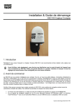
Installation & Quick Start Guide HSC100 Compass Sensor 1. Introduction Congratulations on the purchase of your HSC100 Compass Sensor. It is recommended that your compass sensor is installed by a professional installer. Before operating the unit you should also familiarise yourself again with the user manual of the equipment that you are connecting the HSC100 to. Pay particular attention to the Compass Interfacing section and any settings that need to be configured for correct operation. 2. Before you start The HSC100 is a smart “all in one” Compass solution for small boats. Simply connect the HSC100 to a 12v or 24v DC supply and it will immediately start calculating the heading of the boat and outputting this data in NMEA 0183 format (4,800 baud) or Furuno AD-10 format. The HSC100 outputs compass data at a frequency of ten times a second making it ideal for smooth radar overlay on chart plotters, ‘course-up’ Radar input or for driving an autopilot. It is housed in a waterresistant enclosure so it can be mounted outside in steel hulled boats. Carefully consider how you wish to connect the HSC100 to your existing navigation system before you start installing cables. To display the Compass data you will need: Suitable dedicated chart plotter or radar that can read and display Compass data via NMEA0183 ® ® Or a suitable PC Navigation software running on a PC with Microsoft Windows XP /Windows 2000 or Windows ® ® Vista /Windows 7 with a free RS232 serial port or a free USB port and USB to serial port adaptor. QUICK START HSC100-01-VR1 DIGITAL YACHT LTD HSC100 Quick Start Guide 3. Installation Before starting installation select a suitable location for the HSC100 Sensor. The ideal position for a fluxgate compass sensor is in the centre of the boat where pitch and roll is minimised. The HSC100 should also be mounted as far away as possible from metal objects that are regularly moved or electrical cables/equipment. Effects from fixed metal objects can be calibrated out, but if a metal object is placed near or moved away from the sensor after calibration, inaccuracies could occur. The HSC100 should be fixed to a vertical bulkhead in an upright orientation using the fixing holes shown in the diagram. It does not matter which direction the HSC100 faces, as the azimuth can be set to North at any time. 4. Electrical Connections The HSC100 is supplied with 15m of cable and this should be routed through the vessel to a suitable dry internal location where it can be connected to the boat’s DC power system and the equipment it will be interfaced with. The cable can be shortened, lengthened or joined without problems. The HSC100 should be connected to the boat’s DC supply via a 1 Amp fuse. The unit requires 8V to 30V DC supply voltage. Typical supply current during operation is approx. 25mA. Note that the operation of the LED adds another 10mA and that during auto-calibration the consumption can be as high as 60mA. Below are the wiring details for the HSC100 and a diagram showing the two push button switches; Wiring Colours; Red Black Yellow Green White Brown Violet Blue Screen Power + (12v or 24v) Power – (0v) NMEA Out + NMEA Out – NMEA In+ (not used) NMEA In– (not used) Furuno AD-10 Data Furuno AD-10 Clock Ground The HSC100 can provide compass data in two industry standard formats; NMEA0183 and Furuno AD-10 format. The following section explains these two formats. HSC100 Quick Start Guide DIGITAL YACHT LTD NMEA-0183 There are two versions of the HSC100 and both output NMEA data at 4800 baud, no partity, 1 stop and start bit. The NMEA 0183 data sentences that the HSC100 outputs, will depend upon the model you have; HSC100 - pre-configured to output $HCHDG,xxx.x,,,,*yy. HSC100T - pre-configured to output $HEHDT,xxx.x*yy and $HEROT,z.z,A*yy Where XXX.X = the compass heading, Z.Z = the rate of turn and YY = the NMEA checksum. For interfacing to some systems, it is necessary to re-configure the HSC100 to output different NMEA sentences. This is possible and a Tech Note is available that explains this procedure. Please download Tech Note 00041-2012 from the Support section of our www.digitalyacht.co.uk website. Furuno AD-10 The HSC100 has a separate, dedicated output in Furuno AD-10 format. This is a proprietary 4 character serial format, which gives heading in degrees and tens of minutes. The string 0872 represents the heading 87° 20’ so that the precision is to 1/6 of a degree. At the same time the HSC100 would be also sending the NMEA data to a precision of 1/10 of a degree. Clock Data 480µs Duration of data is 16 clocks each high=low=30µs. Total = 480µs. 100ms minimum Frequency of data packets is set by the interval command. Max = 10Hz 5. Calibrating the Compass When any compass is installed the magnetic characteristics of the whole installation affect the way the Earth’s field reaches the detector inside the device. Each individual installation will be different and so the HSC100 is equipped with an auto-calibration routine which corrects for these installation distortions of the magnetic field. Calibration must always be done with the unit in its final mounted position. The essential point of the calibration is to remove the influence of nearby pieces of iron and steel –so it is essential that these remain unchanged after calibration. If any significant iron component is altered – such as the installation of new equipment or replacement of equipment such as winches or engines – then the calibration must be re-done. Compass Calibration is best done in calm waters when no other vessels are around and with minimum wind and tide; 1) Steer a straight course of around 180º and when safe to do so 2) Start a slow turn to starboard (clockwise). 3) As you pass through 270º press the push button Switch 1 4) Continue your turn at a slow and constant speed, through a full 400º. It is important that the turn is completed at a constant rate, taking no less than 60 seconds and no more than 180 seconds. 4 3 1 2 DIGITAL YACHT LTD HSC100 Quick Start Guide During the auto-calibration process, the Blue Status LED on the HSC100 will flash as follows; State 1 State 2 State 3 Un-calibrated In the process of calibration Calibrated long flash continuous short flash If something should happen that stops you from safely completing the calibration, such as a vessel approaching or an obstruction, press and hold both push buttons together for 1 second. This will cancel the calibration and leave the unit in an un-calibrated state. If the calibration completes successfully, the HSC100 Status LED should change from being on continuously to short flashes. Once calibrated, it is important to zero any alignment offset and this is done by steering the boat to North (000º) as per the conventional magnetic steering compass or failing this the GPS course over the ground (make sure GPS is set to display magnetic headings). Once you are happy that the boat is steering a course of 000º degrees (magnetic), press push button Switch 2. Calibration and Alignment is now complete.