1
CD Automation srl
1 Important warnings for safety ________________________________________ 8
2 Note ____________________________________________________________ 9
3 Identification and Order Code _______________________________________ 10
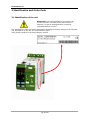
3.1 Identification of the unit ______________________________________________ 10
3.2 Order Code ________________________________________________________ 11
4 Technical Specifications ____________________________________________ 12
4.1 Environmental installation conditions ____________________________________ 12
4.2 Derating Curve _____________________________________________________ 12
5 Installation ______________________________________________________ 12
5.1 Dimensions and Weight ______________________________________________ 13
5.2 Fixing holes ________________________________________________________ 13
6 Wiring instructions ________________________________________________ 14
6.1 Out Terminal (Terminal block M1) ______________________________________ 14
6.2 Supply Terminal (Terminal block M2) ____________________________________ 14
6.3 Communication Terminal RS485 (Terminal block M3) _______________________ 14
6.4 Input Terminal (Terminal block M4) _____________________________________ 14
6.5 Connection Diagram _________________________________________________ 15
6.6 Access to Ln – Tn terminal Screw _______________________________________ 17
7 TU Module Basic __________________________________________________ 18
8 Control Panel ____________________________________________________ 19
9 Display _________________________________________________________ 21
9.1 Indicators _________________________________________________________ 22
9.2 Possible outputs REVO TCM (Temperature Controller only) ___________________ 22
9.3 Possible outputs REVO TC (SSR + Temperature Controller) __________________ 22
10 Operative Mode__________________________________________________ 23
11 Functions ______________________________________________________ 24
11.1 Special Functions __________________________________________________ 24
11.2 Manual Mode______________________________________________________ 25
11.3 Showing break-down alarm __________________________________________ 25
11.4 Showing leakage alarm _____________________________________________ 26
11.5 Showing loop-break alarm ___________________________________________ 26
12 Function “Soft start”______________________________________________ 26
13 Detection of malfunctions__________________________________________ 27
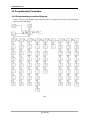
14 Programming Procedure___________________________________________ 28
14.1 Programming procedure Diagram______________________________________ 28
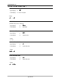
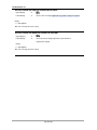
14.2 SET POINT Group ( SP )_____________________________________________ 29
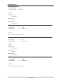
14.3 ALARM Group ( AL ) ________________________________________________ 31
14.3.1 Alarm Function _________________________________________________________________ 33
14.3.2 Alarm Hysteresis _______________________________________________________________ 36
pag. 3 di 121