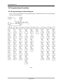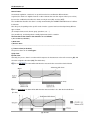
1
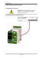
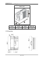
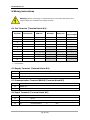
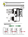
USER’S MANUAL
Rev. 12/2010
00005
Revo
TC
Temperature Controller
Part 1
CD Automation srl
pag. 2 di 121
CD Automation srl
1 Important warnings for safety ________________________________________ 8
2 Note ____________________________________________________________ 9
3 Identification and Order Code _______________________________________ 10
3.1 Identification of the unit ______________________________________________ 10
3.2 Order Code ________________________________________________________ 11
4 Technical Specifications ____________________________________________ 12
4.1 Environmental installation conditions ____________________________________ 12
4.2 Derating Curve _____________________________________________________ 12
5 Installation ______________________________________________________ 12
5.1 Dimensions and Weight ______________________________________________ 13
5.2 Fixing holes ________________________________________________________ 13
6 Wiring instructions ________________________________________________ 14
6.1 Out Terminal (Terminal block M1) ______________________________________ 14
6.2 Supply Terminal (Terminal block M2) ____________________________________ 14
6.3 Communication Terminal RS485 (Terminal block M3) _______________________ 14
6.4 Input Terminal (Terminal block M4) _____________________________________ 14
6.5 Connection Diagram _________________________________________________ 15
6.6 Access to Ln – Tn terminal Screw _______________________________________ 17
7 TU Module Basic __________________________________________________ 18
8 Control Panel ____________________________________________________ 19
9 Display _________________________________________________________ 21
9.1 Indicators _________________________________________________________ 22
9.2 Possible outputs REVO TCM (Temperature Controller only) ___________________ 22
9.3 Possible outputs REVO TC (SSR + Temperature Controller) __________________ 22
10 Operative Mode__________________________________________________ 23
11 Functions ______________________________________________________ 24
11.1 Special Functions __________________________________________________ 24
11.2 Manual Mode______________________________________________________ 25
11.3 Showing break-down alarm __________________________________________ 25
11.4 Showing leakage alarm _____________________________________________ 26
11.5 Showing loop-break alarm ___________________________________________ 26
12 Function “Soft start”______________________________________________ 26
13 Detection of malfunctions__________________________________________ 27
14 Programming Procedure___________________________________________ 28
14.1 Programming procedure Diagram______________________________________ 28
14.2 SET POINT Group ( SP )_____________________________________________ 29
14.3 ALARM Group ( AL ) ________________________________________________ 31
14.3.1 Alarm Function _________________________________________________________________ 33
14.3.2 Alarm Hysteresis _______________________________________________________________ 36
pag. 3 di 121
CD Automation srl
14.3.3 Alarm Out _____________________________________________________________________ 36
14.3.4 Action of alarm output. ___________________________________________________________ 37
14.3.5 Resetting of an Alarm ____________________________________________________________ 37
14.3.6 Alarm mask ___________________________________________________________________ 38
14.4 Control Group ( Cntr ) _____________________________________________ 39
14.5 OUT Group( Out ) _________________________________________________ 42
14.6 Group EHT (Functions setted also from input1 and input2)__________________ 44
14.7 Group DEF (default of run time Loading)________________________________ 46
14.8 Group PAL1 (Pallet 1 control parameters)_______________________________ 46
14.9 Group PAL2 (Pallet 2 control parameters)_______________________________ 48
14.10 Group PAL3 (Pallet 3 control parameters)______________________________ 48
15 SELF-TUNING Algorithms __________________________________________ 51
15.1 PreTune__________________________________________________________ 51
15.2 SelfTune _________________________________________________________ 52
16 Serial RS485 and USB communication interface_________________________ 53
17 Configuration Mode ______________________________________________ 54
17.1 Description _______________________________________________________ 54
17.2 Configuration procedure diagram ______________________________________ 55
17.3 Group INPUT (inP ) ________________________________________________ 57
17.4 Group I/O ( io ) ___________________________________________________ 59
17.4.1 Out 1 ________________________________________________________________________ 59
17.4.2 OUT 2 ________________________________________________________________________ 60
17.4.3 OUT 3 or Di 1 __________________________________________________________________ 61
17.4.4 Out 4 ________________________________________________________________________ 63
17.4.5 General_______________________________________________________________________ 64
17.5 ALARM Group( AL )_________________________________________________ 65
17.5.1 Alarm 1_______________________________________________________________________ 65
17.5.2 Alarm 2_______________________________________________________________________ 66
17.5.3 Alarm 3_______________________________________________________________________ 67
17.6 Heating Break-Down Group ( Hbdu ) __________________________________ 68
17.7 Loop break Group( LbAL ) ___________________________________________ 68
17.8 SELFTUNE Group( tunE )____________________________________________ 69
17.9 SOFT START Group ( SoFt )__________________________________________ 70
17.10 Gruppo PARAMETRI VARI ( niSC ) ___________________________________ 70
17.11 RS485 Group ( r485 )_____________________________________________ 73
17.12 Default Configuratiov Group ( deF )__________________________________ 74
17.13 Notes___________________________________________________________ 75
18 Serial communications ____________________________________________ 76
pag. 4 di 121
CD Automation srl
18.1 introduction to Modbus Protocol _______________________________________ 76
18.2 TABLE 0 _________________________________________________________ 78
18.3 WORDS ADDRESS__________________________________________________ 78
18.4 BITS ____________________________________________________________ 87
18.5 TABLE 1 (WEST 6600) ______________________________________________ 88
18.6 Status Table (Word 7) ______________________________________________ 89
19 Default Parameter Loading_________________________________________ 91
19.1 User procedure ____________________________________________________ 91
19.2 Loading Default operative parameter ___________________________________ 91
19.3 Default configuration parameter Loading ________________________________ 92
19.3.1 European table _________________________________________________________________ 93
19.3.2 Americana table ________________________________________________________________ 96
20 Calibration Procedure ____________________________________________ 101
20.1 Description ______________________________________________________ 101
20.2 Guidelines for calibration ___________________________________________ 101
20.3 Calibration from keypad ____________________________________________ 102
20.3.1 TC and linear input calibration ____________________________________________________ 103
20.3.2 Cold Junction Calibration ________________________________________________________ 104
20.3.3 RTD Input Calibration ___________________________________________________________ 105
20.3.4 Input Calibration mA ___________________________________________________________ 106
20.3.5 Input 10 V Calibration __________________________________________________________ 107
20.3.6 Current transformer Input calibration_______________________________________________ 108
20.4 Calibration from serial _____________________________________________ 109
20.4.1 Input TC and LINEAR Input calibration ______________________________________________ 109
20.4.2 Cold Junction Calibration ________________________________________________________ 110
20.4.3 RTD Input Calibration ___________________________________________________________ 110
20.4.4 Input Calibration mA ___________________________________________________________ 111
20.4.5 Input 10 V Calibration __________________________________________________________ 112
20.4.6 Calibrazione Input Trasformatore Amperometrico _____________________________________ 113
20.5 Caricamento valori di calibrazione di default ____________________________ 113
21 Tables: _______________________________________________________ 114
21.1 Table 1 _________________________________________________________ 114
21.2 Table 2 _________________________________________________________ 114
22 Test Hardware via seriale _________________________________________ 115
22.1 Display Test _____________________________________________________ 116
22.2 Led Test ________________________________________________________ 116
22.3 FUNC key Test ___________________________________________________ 116
22.4 MAN Key Test ____________________________________________________ 116
22.5 UP key Test ______________________________________________________ 116
22.6 DOWN key Test___________________________________________________ 116
22.7 EEPROM Test_____________________________________________________ 116
pag. 5 di 121
CD Automation srl
22.8 Relè 1 Test ______________________________________________________ 116
22.9 Relè 2 Test ______________________________________________________ 116
22.10 Relè 3 Test _____________________________________________________ 117
22.11 Relè 4 Test _____________________________________________________ 117
22.12 Out 4 mA Test___________________________________________________ 117
22.13 Out 20 mA Test__________________________________________________ 117
22.14 Input 1 Test ____________________________________________________ 117
22.15 Input 2 Test ____________________________________________________ 117
22.16 10 mV measure Test______________________________________________ 118
22.17 60 mV measure Test______________________________________________ 118
22.18 4 mA measure Test_______________________________________________ 118
22.19 20 mA measure Test______________________________________________ 118
22.20 0 ohm measure Test ______________________________________________ 119
22.21 300 ohm measure Test ____________________________________________ 119
22.22 1 V measure Test ________________________________________________ 119
22.23 10 V measure Test _______________________________________________ 119
22.24 RJ Test ________________________________________________________ 120
22.25 TA 5 mA measure Test ____________________________________________ 120
22.26 TA 50 mA measure Test ___________________________________________ 120
pag. 6 di 121
CD Automation srl
CD Automation
s.r.l.
Controllers, Drives & Automation
Via Picasso, 34/36 - 20025 Legnano (MI)- Italia
P.I. 08925720156 -Tel. (0331) 577479 - Fax (0331) 579479
Internet : www.cdautomation.com - E-MAIL: [email protected]
Dichiarazione di Conformità
Declaration of Conformity
PRODUTTORE:
PRODUCT MANUFACTURER:
CD Automation S.R.L.
INDIRIZZO:
ADDRESS:
Via Pablo Picasso 34//36
20025 Legnano (Mi)
Italia
Dichiara che il prodotto:
Declare that the product:
Revo TC
SODDISFA I REQUISITI DELLA NORMA :
Specifica di sicurezza
EN60947-1 :2008
EN60947-4-3:2001
Specifica sulle emissioni
EN60947-4-3:2000
Specifica sulle Immunità
EN60947-4-3:2000
FULFILS THE REQUIREMENTS OF THE STANDARD:
Electrical safety Standard
EN60947-1 :2008
EN60947-4-3:2001
Generic Emission standard EN60947-4-3:2000
Generic Immunity standard EN60947-4-3:2000
CDAutomation dichiara che I prodotti sopra menzionati sono conformi alla direttiva
CDAutomation declares that The products above mentioned they am conforming to the directive
EMC 2004/108/CEE e alla direttiva Bassa Tensione (low Voltage) 2006/95/CEE
DESCIZIONE DEL PRODOTTO:
PRODUCT DESCRIPTION:
Unità di controllo potenza elettrica
Elettric power controll
UTILIZZO:
SCOPE OF APPLICATION:
Controllo processi termici
Thermal controll process
Data di emissione: 20/04/2010
Issued on:
20/04/2010
Amministratore Unico e
Legale Rappresentante
Claudio Brizzi
pag. 7 di 121
CD Automation srl
1 Important warnings for safety
This chapter contains important information for the safety. The not observance of these instructions may
result in serious personal injury or death and can cause serious damages to the Thyristor unit and to the
components system included.
The installation should be performed by qualified persons.
The Thyristor unit are integral part of industrial equipments. When it is supply, the
Thyristor unit is subject to dangerous tensions.
•
Don't remove the protection Cover.
•
Don't use these unit in aerospace applications and/ or nuclear.
The nominal current corresponds to use at temperature not superior to 45°C.
•
The Thyristor unit must be mounted in vertical position and without obstruction above
and below to allow a good flow ventilation.
•
The hot air of one thyristor unit must not invest the unit positioned above.
•
For side by side placed leave a space of 15mm between the unit.
A suitable device must ensure that the unit can be electrically isolated from the supply, this
allows the qualified people to work in safety.
Protection (Protection, Protezione)
The unit have IP20 protection rating as defined by the specific international. Is necessary
consider the place of installation.
Earth (Terre, Messa a terra)
For safety, the Thyristor unit with isolated heat-sink must be connected to earth.
Earth impedance should be correspondent to local earth regulation. Periodically the earth
efficiency should be inspected.
Electronic supply (Alimentation électronique, Alimentazione elettronica)
The electronic circuit of the Thyristor unit must be supplied by dedicated voltage for all
electronic circuits and not in parallel with coil contactors, solenoids and other.
It's recommended to use a shielded transformer.
Electric Shock Hazard (Risque de choque électrique, Rischi di scosse elettriche)
When the Thyristor unit is energized, after the power supply is shut off, wait least a minute
for allow the discharge of the internal capacitors where there is a dangerous tension. Before
working, make sure that:
•
Only authorized personnel must perform maintenance, inspection, and replacement
operations.
•
The authorized personnel must read this manual before to have access to the unit.
•
Unqualified People don't perform jobs on the same unit or in the immediate vicinities.
pag. 8 di 121
CD Automation srl
Important warnings (Attention, Avvertenze importanti)
During the operations with units under tension, local regulations regarding electrical
installation should be rigidly observed:
•
Respect the internal safety rules.
•
Don't bend components to maintain insulation distances.
•
Protect the units from high temperature humidity and vibrations.
•
Don't touch components to prevent electrostatic discharges on them.
•
Verify that the size is in line with real needs.
•
To measure voltage current etc. on unit, remove rings and other jewels from fingers
and hands.
•
Authorized personnel that work on thyristor unit under power supply voltage must be
on insulated board
This listing does not represent a complete enumeration of all necessary safety cautions.
Electromagnetic compatibility
(Compatibilità électromagnétique, Compatibilità elettromagnetica)
Our thyristor units have an excellent immunity to electromagnetic interferences if all
suggestions contained in this manual are respected. In respect to a good Engineering
practice, all inductive loads like solenoids contactor coils should have a filter in parallel.
Emissions (Emission, Emissioni)
All solid-state power controllers emit a certain amount of radio-frequency energy because
of the fast switching of the power devices.
The CD Automation’s Thyristor unit are in accord with the EMC norms, CE mark.
In most installations, near by electronic systems will experience no difficulty with
interference. If very sensitive electronic measuring equipment or low-frequency radio
receivers are to be used near the unit, some special precautions may be required. These
may include the installation of a line supply filter and the use of screened (shielded) output
cable to the load.
2 Note
Warning: This icon is present in all the operational procedures where the Improper
operation may result in serious personal injury or death
Caution: This icon is present in all the operational procedures where the Improper
operation can cause damage for the unit.
CD Automation reserves the right to modify the own products and this manual without any
advise.
pag. 9 di 121
CD Automation srl
3 Identification and Order Code
3.1 Identification of the unit
Attenzione: Prima dell’installazione, assicurarsi che
l'unità a thyristor non abbia subito danni durante il
trasporto. In caso di danneggiamento, notificarlo
immediatamente al corriere..
The identification's label give all the information regarding the factory settings of the Thyristor
unit, this label is on the unit, like represented in figure.
Verify that the product is the same thing as ordered.
pag. 10 di 121
CD Automation srl
3.2 Order Code
pag. 11 di 121
CD Automation srl
4 Technical Specifications
4.1 Environmental installation conditions
Ambient temperature
0-40°C at nominal current. Over 40°C use the
derating curve.
Storage temperature
-25°C a 70°C
Don’t install at direct sun light, where there
are conductive dust, corrosive gas, vibration or
water and also in salty environmental.
Up to 1000 meter over sea level. For higher
altitude reduce the nominal current of 2% for
each 100m over 1000m
Installation place
Altitude
Humidity
From 5 to 95% without condense and ice
Pollution Level
Up to 2nd Level ref. IEC 60947-1 6.1.3.2
4.2 Derating Curve
5 Installation
Before to install, make sure that the Thyristor
unit have not damages.
If the product has a fault, please contact the
dealer from which you purchased the product.
Verify that the product is the same thing as
ordered.
The Thyristor unit must be always mounted in
vertical position to improve air cooling on
heat-sink.
Maintain the minimum distances in vertical
and in horizontal as represented.
When more unit has mounted inside the
cabinet maintain the air circulation like
represented in figure.
Sometimes is necessary installing a fan to
have better air circulation.
pag. 12 di 121
CD Automation srl
5.1 Dimensions and Weight
REVO TC 1PH
W(mm)
H(mm)
D(mm)
Weight (kg)
72
121
185
1,15
5.2 Fixing holes
pag. 13 di 121
CD Automation srl
6 Wiring instructions
Warning: Before connecting or disconnecting the unit check that power and
control cables are isolated from voltage sources.
6.1 Out Terminal (Terminal block M1)
Digital
Terminal
Description
SSR Out
DI Input
Relay Out
Input/Output
1
OUT4
SSR–
DI2
C
DI/O 2
2
OUT4
SSR+
DI2
NO
DI/O 2
3
OUT3
SSR–
DI1
C
DI/O 1
4
OUT3
SSR+
DI1
NO
DI/O 1
5
OUT2
SSR–
_
C
_
6
OUT2
SSR+
_
NO
_
7
TA
_
_
_
_
8
TA
_
_
_
_
9
OUT1
SSR–
_
C
_
10
OUT1
SSR+
_
NO
_
“-“ = Not available
6.2 Supply Terminal (Terminal block M2)
Terminal
Description
11
Supply 24Vdc/ac
12
Supply 24Vdc/ac
6.3 Communication Terminal RS485 (Terminal block M3)
Terminal
Description
A+
RS485 A +
B-
RS485 B -
6.4 Input Terminal (Terminal block M4)
Terminal
Description
13
PT100
14
TC+
PT100
V+
mA+
15
TC-
Compensazione
V-
mA-
pag. 14 di 121
CD Automation srl
6.5 Connection Diagram
Revo TC Basic:
Revo TC with flat wiring system Option:
pag. 15 di 121
CD Automation srl
Caution: this procedure must be performed only by qualified persons.
* See Out terminal chapter for more informations
*2 Only with flat wiring system Option: connect with proper cable (RJ45 Cat 5E Patch Cable UTP)
as shown:
pag. 16 di 121
CD Automation srl
The cable supplyed by CD Automation are
Lenght
0,15 m
Code
ICOC U5EB-001
0,3 m
ICOC U5EB-003-GREE
0,5 m
ICOC U5EB-005-GREE
1m
ICOC U5EB-010-GREE
2m
ICOC U5EB-020-GREE
3m
ICOC U5EB-030-GREE
5m
ICOC U5EB-050-GREE
7,5 m
ICOC U5EB-075-GREE
10 m
ICOC U5EB-100-GREE
15 m
ICOC U5EB-150-GREE
6.6 Access to Ln – Tn terminal Screw
pag. 17 di 121
CD Automation srl
7 TU Module Basic
Revo TU is a termination unit that provides the power supply and RS485 comms (modbus RTU) for up to
max 10 REVO TC units.
Terminal block M1
Terminal
Description
1
RS485 B -
2
RS485 A +
3
Global Output
4
Global Output
Terminal block M2
Terminal
Description
5
Not Used
6
Supply 24Vdc/ac
7
Supply 24Vdc/ac
Terminal Block M3 for flat wiring system
pag. 18 di 121
CD Automation srl
8 Control Panel
The keyboard is composed of four push button properly identified and protected: depending on the status
of each device button assumes a specific function, as described below.
Text or Combination
Description of function associated
Configuration and operational
Skip to next parameter or group
Configuration and ongoing operational and edit
Increases the value of the parameter currently displayed
▲
Operating with manual output
Increases the value of control output
Automatic Operation
If enabled, after 3 sec ill set point increases
Configuration and operational
Skip to the previous group or parameter
Configuration and ongoing operational and edit
Decreases the value of the parameter currently displayed
▼
Operating with manual output
Decreases the value of control output
Automatic Operation
If enabled, after 3 sec the set point decreases
Operating
Release
Avoid the Change of the value displayed through the upper LCD.
Accept the changed value
Operating
F UN C
T> 3 sec
Special Views: load current, leakage current, heating power, the cooling power, firmware version.
Configuration
Avoid the Change of the value of information displayed through the upper LCD.
Accept the changed value
Operating
Exit the current group
While editing a parameter abort editing
Operating
T> 3 sec
Set automatic or manual control mode
MA N
Configuration
Exit the current group
While editing a parameter abort editing
pag. 19 di 121
CD Automation srl
Operating
during numeric editing
Reaches the max / min set for the actual parameter
(▲ / ▼) + M AN
Configuration
during numeric editing
Reaches the max / min set for the current parameter
Operating
F UN C + MA N
t > 3 sec.
Input in configuration mode
Operating
▲ + F UN C
t > 3 sec.
Lamp test
Operating
▼ + F UN C
t > 3 sec.
Input in calibration mode
Operativo
▼ + MA N
Show on
the display below the load current or SetPoint
pag. 20 di 121
CD Automation srl
9 Display
During operation, normal operating, the top display shows the process variable while the lower display the
current setpoint.
Note:
if the restriction is enabled to changes in setpoint (SPU, SPD), the setpoint value
displayed may not match the actual value. In fact, if the group parameter SPUS misc
configuration is set to appear FNSP the SP arrival, otherwise the current SP.
If properly enabled in the configuration you can increase or decrease the setpoint value directly from the
operating mode.
To this should be button for 3 seconds. taken down ▼ or ▲
At this point the change is enabled. Each press of two buttons will cause the 'increase or decrease of the
SP.
Failure pressure of either button for more than 5 seconds will stop the 'edit.
To resume editing the SP press again require either button for 3 seconds.
If properly enabled configuration by pressing the UP and MAN on the lower display shows the current in
the load. To return to the set point, press the same buttons.
pag. 21 di 121
CD Automation srl
9.1 Indicators
LED1
Switched on when the output 1 is ON state.
LED2
Switched on when the output 2 is ON state.
LED3
Switched on when the output 3 is ON state.
LED4
Switched on when the output 4 is ON state.
LED5
Flashing when the function tune is working and in calculating mode.
LED6
Flashing when the function adaptive is working.
The Led 1, 2, 3 o 4 , if assigned to the status of the alarm 3, take the following feature:
If the alarm 3 is in OFF state and also alarms Breakdown, leakage or loop-break are in OFF state
the assigned LEDs are off
If the alarm 3 is in ON state and also alarms breakdown, leakage or loop-break are in OFF state
the assigned LEDs are On
If the alarm 3 is in OFF state and one or more of the alarm of breakdown, leakage or di loopbreak are in ON state, the assigned LEDs flashes every 1 second.
If the alarm 3 is in ON state and one or more of the alarm of breakdown, leakage or loop-break
are in ON state, the assigned LEDs flashes every 0.5 seconds.
9.2 Possible outputs REVO TCM (Temperature Controller only)
RELAY
SSR
Analogic
DI Input
Input/Output
TC07-02
TC07-03
TC07-01
TC07-05
TC07-04
OUT1
X
X
X
-
-
OUT2
X
X
-
-
-
OUT3
X
X
X
X
X
OUT4
X
X
-
X
X
Uscita
“-“ = Not available
9.3 Possible outputs REVO TC (SSR + Temperature Controller)
RELAY
SSR
Analogic
DI Input
Input/Output
TC07-02
TC07-03
TC07-01
TC07-05
TC07-04
OUT1
-
Fixed
-
-
-
OUT2
X
-
-
-
-
OUT3
X
-
--
X
-
OUT4
Fixed
-
-
-
-
Uscita
“-“ = Not available
pag. 22 di 121
CD Automation srl
10 Operative Mode
Description:
In operating mode, parameters can be viewed and modified in the present state of the device: to access
the programming procedure, press the F UN C button and release it within 3 seconds.
The lower display shows the ID of the current group, while the upper display shows the string "Edt"
permanently: the ▲ and ▼ buttons let you select the group to change, and allows the F U N C key to
enter the selected group.
For each parameter in the group selected, the lower display shows the ID parameter as the upper display
shows the current value: to switch to other parameters of the group acts on the ▲ and ▼.
Pressing the F U NC enter into modification of the displayed parameter (the upper display starts
flashing).
With the ▲ and ▼ changing the current value displayed on the bottom.
Press the F UN C key to store the value currently displayed, pressing the MAN you exit without saving
changes the new value.
For a list of parameters, see Chapter <Programming procedure>
pag. 23 di 121
CD Automation srl
11 Functions
11.1 Special Functions
By pressing for 3 sec the keys UP and MAN and the lower display, if enabled, the load current.
The next press the same button for 3 seconds will return to the SetPoint
By pressing the F U NC key for 3 seconds, you can see on the lower display in the following order:
• A character A followed by the value of the load current output.
• A character b followed by the leakage current value of output.
• A character H followed by the output value of heating (0-100%)
•A character C followed by cooling output value (0 - 100%)
• A t character followed by the value of the cold junction temperature detected
• A v character followed by the firmware version
Some information is only available if the instrument is properly configured.
The display returns to normal operating mode by pressing the MAN.
Pressing the ▲ + F UN C for 3 seconds activates the lamp test: all segments of all digits of the display
and front LEDs are switched on and off with 1 Hz frequency (duty-cycle 50%) until next keypress MAN.
pag. 24 di 121
CD Automation srl
11.2 Manual Mode
The manual mode can be activated by holding down the MAN button for 3 seconds, if enabled in the
configuration (group misc parameter mnFn <> nonE) and only in normal operating mode.
Il display superiore visualizza la variabile di processo.
Esistono 3 modalità di funzionamento manuale ( sempre definite in configurazione nel gruppo misc
parametro mnFn):
The upper display shows the process variable.
There are 3 modes of operation manual (always defined in the configuration parameter group misc
mnFn):
Classic Manual Mode:
The operator sets the percentage of output power from 0 to 100% for heating only operation, from
-100% to 100% for operating heating / cooling.
The lower display shows the current power preceded by the letter P.
The change from automatic mode to manual mode (and vice versa) will be in bumpless mode
only if the integral action has not been previously excluded.
If the transfer AUTO ► MAN occurred during selftune, at the return in the AUTO mode the
instrument will operate in auto-tuning adaptive abled.
OFF Mode: the operator determines the release of relay heating (if output in mA or V brings the
power to 0).
Displayed load current mode: in this case does not change any control over the load, but
show the load current.
When switch on, the device is always in AUTO mode or, if properly selected in configuration ,the state in
which it was turned off.
11.3 Showing break-down alarm
The alarm condition detected in the measurement of current through the current transformer is indicated
in OR on the relay or on the relays assigned to alarm 3.
The current sampling is done only if the state's output, which is inserted in the current transformer is
maintained for at least 200ms ON: if during the current cycle time is not carried out any sampling, the
value shown by the lower display will be "----".
This is shown only present if the group parameter HCEn Hbdu configuration is set to ON.
pag. 25 di 121
CD Automation srl
11.4 Showing leakage alarm
The alarm condition detected in the measurement of current through the current transformer is indicated
in OR on the relay or on the relays assigned to alarm 3.
Il The current sampling is done only if the state's output, which is inserted in the current transformer is
unenergized for at least 200ms:if during the current cycle time is not carried out any sampling, the value
shown by the lower display will be "----".
This view is only present if the group parameter HCEn Hbdu configuration is set to ON.
11.5 Showing loop-break alarm
• uscita di controllo al minimo e azione reverse
• uscita di controllo al massimo e azione direct
Analogamente, la variabile di processo deve crescere se:
• uscita di controllo al minimo e azione direct
• uscita di controllo al massimo e azione reverse
La condizione di allarme viene segnalata in OR sul relè o sui relè assegnati all' allarme 3.
The loop-break alarm is generated by the dedicated algorithm when the control output is at the minimum /
maximum
value and the process variable changes in the time pre-chosen of amplitude below the
threshold set in the configuration.
The process variable must decrease if:
• Control output to the minimum and Reverse Action
• Control output to the maximum and direct action
Similarly, the process variable must grow if:
• Control output to the minimum and direct action
• Control output to the maximum and reverse action
The alarm condition is reported in OR on the relay or the relays assigned to the alarm 3.
12 Function “Soft start”
When the instrument is switched on the function "soft start" protects temporarily the limit the output
power. By limiting the heating power of switch on it’s possible to reduce the thermal stress to the heating
elements. The user can configure the time and temperature threshold of the function "soft start".
pag. 26 di 121
CD Automation srl
13 Detection of malfunctions
The instrument can detect the following abnormal conditions of the process variable:
• over-range
• under-range
• sensor leads break
The condition of over-range is displayed by the characters "Undr" flashing in the upper display.
The condition of over-range is displayed with "oVrr" in the upper display.
Table 1 shows the state of OUT1 and OUT2 at the conditions of range of under-and over-range, according
to the device settings (control mode heating / cooling and SEcF parameter value). The first four lines
delineate the standard configuration.
OUT1
condition
Heating/
Cooling
OUT2
SEcF
reverse
direct
reverse
direct
under-range
NO
0
ON
OFF
---
---
over-range
NO
0
OFF
ON
---
---
under-range
SI
0
ON
OFF
over-range
SI
0
OFF
ON
under-range
---
1
SEcO
SecO
over-range
---
1
SEcO
SecO
under-range
---
2
standard
standard
over-range
---
2
SEcO
SecO
under-range
---
3
SEcO
SecO
over-range
---
3
standard
standard
Table 1: security state Stati di sicurezza of the output in out-of-range condition.
Breakage of the temperature sensor can be reported as:
• over-range o under-range (configurable) for input TC/mV
• over-range for input RTD
• under-range for input mA / V (only with zero elevation)
pag. 27 di 121
CD Automation srl
14 Programming Procedure
14.1 Programming procedure Diagram
Figure 1 shows the state diagram of the programming process through which shows the strings displayed
by the two front LCD display.
Fig 1
pag. 28 di 121
CD Automation srl
14.2 SET POINT Group ( SP )
SETPOINT
SP
Upper Display
Lower Display
Valore di setpoint
Range
rL ↔ rH
SELFTUNE
(available only if can be activated)
Upper Display
Stun
Lower Display
On or Off
AUXILIARY SETPOINT
Upper Display
SP1
Lower Display
Setpoint value
Range
rL ↔ rH
LOWER SETPOINT LIMIT
Upper Display
rL
Lower Display
Lower limit value
Range
LoSc ↔ rH
UPPER SETPOINT LIMIT
Upper Display
rH
Lower Display
Upper limit value
Range
rL ↔ HiSc
pag. 29 di 121
CD Automation srl
RATE OF CHANGE FOR POSITIVE CHANGES OF SETPOINT
Upper Display
SPu
Lower Display
Value of rate of change applied to any positive change in setpoint.
Range
1 ↔ 100 digit/min
Inf : rate of change forced to a Step.
RATE OF CHANGE FOR NEGATIVE CHANGES OF SETPOINT
Upper Display
SPd
Lower Display
Valore del rate of change applicato a ogni variazione
negativa del setpoint.
Range
1 ↔ 100 digit/min
Inf : rate of change forced to a Step.
pag. 30 di 121
CD Automation srl
14.3 ALARM Group ( AL )
SILENCED ALARM
(appears only with at least one of programmable alarms with manual reset)
Upper Display mrSt
Lower Display on
Functioning:
To silence the active alarms stored, press key F U N C .
ALARM1 THRESHOLD
Upper Display AL1
Lower Display Actual value
Range
Process alarm
Span limit
Band alarm
0 ↔ 500
Deviation alarm
-500 ↔ 500
HYSTERESIS ALARM1
Upper Display
HSA1
Lower Display
Actual value
Range
0.1% ↔ 100.0% of the span or 1LSD
pag. 31 di 121
CD Automation srl
ALARM2 THRESHOLD
Upper Display AL2
Lower Display Actual value
Range
Process alarm
Limit of span
Band alarm
0 ↔ 500
Deviation alarm
-500 ↔ 500
ISTERESI ALARM2
Upper Display
HSA2
Lower Display
Actual value
Range
0.1% ↔ 100.0% of the span or 1LSD
ALARM3 THRESHOLD
Upper Display
AL3
Lower Display
Actual value
Upper Display
HSA3
Lower Display
Actual value
Range
Process alarm
Limit of span
Band alarm
0 ↔ 500
Deviation alarm
-500 ↔ 500
ISTERESI ALARM3
Range
0.1% ↔ 100.0% of the span or 1LSD
pag. 32 di 121
CD Automation srl
14.3.1 Alarm Function
General notes:
An automatic regulation, control and / or supervision takes into consideration different alarms.
In general, the alarms are "digital" elements or rather elements that can take only two values (true or false)
because rhe condition that describes the alarm can only be 'true' (ON) or "false" (OFF).
The condition that describes the alarm is usually summarized by the ALARM FUNCTION because it defines
its behavior.
Over the years, depending on the specific needs of various systems have been developed many different
types of alarm
(for example alarms, trends, alarms group, put alarms, etc. ....).
Here we will only considering alarms normally implemented on this controller.
The Functions of the alarms in the controller are 3 as follows:
1) Process alarm (or absolute)
2) Band Alarm
3) Deviation Alarm
------------------------------------------------------------------------------------------------------------------------------------------1) Process alarm (or absolute)
The process alarm can be of two types:
A) Up alarm
B) Low alarm
Generally, the process alarm is an alarm which compares the instantaneous value of the measure (M) with
the value assigned to the alarm (SA) (Threshold value)
A) If it is an Up alarm, the alarm will be ON when the measured value exceeds the threshold value
B)If it is a Low alarm, the alarm will be ON when the measured value is less than the threshold value
(M < AS).
pag. 33 di 121
CD Automation srl
2) Band Alarm
We define "Contolling system" any automated system capable of performing the necessary actions to
maintain the controlled variable (which usually coincides with the measured variable) as close as possible to
a certain value (which is called set point)
The band alarm is a type of alarm that can only be done on a " Contolling system" beacuse it links the value
of the threshold on the Set point (SP).
In the Band alarm, the alarm threshold defines an area around the set point.
Again there are two possibilities:
A) ON State when the measure is within the bandwidth [(SP - SA)< M < (SP + SA)]
B) ON State when the measure is outside the bandwidth [M<(SP - SA) or M>(SP + SA)]
A) ON State within the bandwidth
B) ON State outside the bandwidth
pag. 34 di 121
CD Automation srl
3) Deviation Alarm
Also the deviation alarm can only be done on a " Controlling system" because it links the value of the
threshold set point but in some ways is a cross between Process and Band alarm .
For this reasons the deviation alarm acts as a process alarm where the alert threshold is added or removed
from the set point.
Again there are two possibilities:
A) deviation alarm Up [M > (SP + SA)]
B) Deviation alarm Down [M < (SP – SA)]
Note:
The band and deviation alarms automatically moving the absolute value of the threshold when you change
the set point value.
The process alarm, however, is indifferent to changes of set points.
pag. 35 di 121
CD Automation srl
14.3.2 Alarm Hysteresis
The purpose of the hysteresis is to prevent, when the measurement is near the thresholdand there are
disturbances on the measure, the alarm state changes continuously from ON to OFF and vice versa.
To do this it’s possible to define a "safety margin" so that the alarm goes ON when the measure reaches a
specified value (A) but does not go OFF before the measure reaches another value (B) more closely to the
optimal condition.
Value (A) Is used as the threshold and value (B) as the threshold more or less hysteresis;
The following example will clarify the foregoing.
Considering that we want to set a Low alarm process that goes ON at least 300 ° C (value A) and returns to
OFF only when the measure has risen to 360 ° C (B value).
In this case the setting of the threshold is 300 (° C)
In questo caso il valore di soglia da impostare è 300 (°C) while the hysteresis have to be set equal to 60(°C).
note. The hysteresis value is expressed on the instrument in % of full scale.
14.3.3 Alarm Out
Generally the state of an alarm is made visible to the user and can also produce physical actions on the
system.
The status indication of an alarm can be:
1) Visual indication (a LED on the front of the instrument panel)
2) Software indication(state of a boolean variable on the serial communication)
3) State of a physical Out (normally a relay)
Note:
a) These three indications are present both individually than simultaneously.
b) At" State of a physical Out " are associated also physical action on the system.
pag. 36 di 121
CD Automation srl
14.3.4 Action of alarm output.
(also indicated as "Alarm Action")
When an alarm status is associated with the state of a physical output (ex. relay)
Quando allo stato di un allarme è associato lo stato di un uscita fisica (es. relè) it’s necessary to define the
relationship between the alarm state and relay state.
Two action are possibile:
1) Direct action: out ON when the alarm is ON (ex.: excited relay when the alarm is ON)
2) Riverse action: Out OFF when the alarm is ON (ex.: un-excited relay when the alarm is ON)
Direct action is the most commonly used but you must remember that the reverse action allows to have an
alarm signal when the instrument does not work or is off(because the ON state of alarm is indicated by the
OFF state of output, when the instrument is switched off or not working the output will be definitely OFF).
In the case of relay output , the status of Output may not be sufficient to describe the state of the contact. In
fact, when the output relay is provided with changeover contacts it is clear that the choice of the normally
closed contact (NC) or normally open (NO) allows for equal status of the relay to reverse the state of the
contact.
However remains the considerations valid regarding the possibility of having an alarm signal when the
instrument is switched off or not working (reverse action).
14.3.5 Resetting of an Alarm
The alarms we have seen are based on the concept that when the measure falls in the OFF area the alarm
also goes OFF automatically. In these cases it is said that the alarm is equipped with automatic reset.
In some cases it is preferable that the alarm still remains in the ON condition even after the measure is back
in the OFF zone, the alarm will return to the OFF condition only after a physical action (pressing a key or
other). In this case we say that the alarm has a manual reset.
The reason of this choice is due to the level of danger of the anomaly reported from the alarm, an
overcurrent can damage the system and cause fire or dangerous situations for the users
Forcing the user to perform an action also ensures that we take note of the report and eliminate the cause of
the problem before resetting the system.
Alarms with manual reset may have different behaviors depending on different situations but, generally, one
can identify two families of behavior:
1) Alarm with unconditioned reset
Are those alarms that, when performed manually reset, set the alarm to OFF condition even if the alarm
condition is still present.
A typical example are the alarms that drive the sirens, once the user reaches the machinery switch off the
siren and then performs the necessary actions to remove the alarm condition. To get a further alarm signal is
necessary that the measure goes to the area OFF and back in the ON area.
pag. 37 di 121
CD Automation srl
2) Alarm with conditioned reset
Are alarms that, when is running the manual reset ,activate the alarm in OFF condition only if the alarm
condition is no longer present.
For the conditioned alarms we have two types:
I. Alarms that require manual reset only after alarm condition has been eliminated
(Otherwise remain in alarm). This is the type of reset on this controller.
II. Alarms that, if they are resetted when the alarm condition is still present, store the reset and run
automatically when the alarm condition disappears.
It should however be noted that, even for resetting, has been developed a multitude of variations and types
to meet the varied needs of the plant. As mentioned above describes only the most common condition and
those normally present on the controllers.
14.3.6 Alarm mask
As we have said in many cases the alarm produces a physical action on the system.
Obviously, however, the alarm is usually set to report defects when the system is "fully operational".
The conditions of the plant startup or after a set point change does not satisfy the condition "fully operational"
and can cause unwanted alarmi.
To avoid unwanted alarms were studied different solutions according to the type of system where the alarm
is applied.
In the controller has been implemented a solution due to the measure.
If at the start up is detected an alarm condition, this condition is ignored until the measure reaches the area
where the alarm is OFF, then the alarm resumed normal function.
If the alarm is programmed as band alarm or deviation, the standby function masks the alarm condition in
start un and set point variation, until the value of process variable reaches the alarm threshold with
hysteresis .
If is a process alarm the alarm conditions mask only during start up.
Se l'allarme è di processo, maschera le condizioni di allarme solamente in accensione.
pag. 38 di 121
CD Automation srl
14.4 Control Group ( Cntr )
PROPORTIONAL BAND
Upper Display
Pb
Lower Display
Actual value
Range
No selftune with O2Fn ≠ Cool
1.0% ↔ 100.0% dello span
No selftune with O2Fn = Cool
1.5% ↔ 100.0% dello span
Selftune with O2Fn ≠ Cool
LPb2 ↔ HPb
Selftune with O2Fn = Cool
LPb1 ↔ HPb
HYSTERESIS
(available only with ON/OFF – CntF = onoF (miSC group of configuration))
Upper Display
HYS
Lower Display
Actual value for ON/OFF
Range
0.1% ↔ 10.0% of span or 1LSD
INTEGRAL TIME
(available only with PID or PI - CntF <> onoF (miSC group of configuration))
Upper Display
ti
Lower Display
Actual value
Range
00.01 ↔ 20.00 mm.ss
Beyond the maximum value, on display the integral action is excluded.
With selftune activated, the lower limit is given by Lti
pag. 39 di 121
CD Automation srl
DERIVATIVE TIME
(availabele only with PI - CntF = Pi (miSC group of configuration))
Upper Display
td
Lower Display
Actual value
Range
00.01 ↔ 10.00 mm.ss
With selftune activated, the derivative time is equal to tI / 4
INTEGRAL PRELOAD
(availabele only with PID or PI - CntF <> onoF (miSC group of configuration))
Upper Display
iP
Lower Display
Actual value
Range
With O2Fn ≠ Cool
0 ↔ 100
With O2Fn = Cool
-100 ↔ 100
pag. 40 di 121
CD Automation srl
RELATIVE COOLING GAIN
(availabele only with PID or PI - CntF <> onoF (miSC group of configuration) with at least one output
set as cooling)
Upper Display
rC
Lower Display
Actual value
Range
0.20 ↔ 1.00
When selftune is active and rCEn = On the range become
PAL = AIr
0.85 ↔ 1.00
PAL = OIL
0.80 ↔ 0.90
PAL = H2O
0.30 ↔ 0.60
DEAD BAND/OVERLAP through HEATING/COOLING OUTPUT
(available only with PID oe PI - CntF <> onoF (miSC group of configuration)) with at least one output
set as cooling)
Upper Display
oLAP
Lower Display
Valore attuale.
Negative values indicate dead band, positive values indicate overlap.
Range
-20 ↔ 50
pag. 41 di 121
CD Automation srl
14.5 OUT Group( Out )
TIME OF CICLE OUT1
(available only with at least one output set as heating not analogic)
Upper Display
CY1
Lower Display
Actual Value.
Range
1 ↔ 200 seconds
SUPERIOR LIMIT OUTPUT
Upper Display
oLH
Lower Display
Actual Value.
Range
With O2Fn ≠ Cool
0 ↔ 100
With O2Fn = Cool
-100 ↔ 100
TIME OF CICLE OUT2
(available only with at least one output set as heating not analogic)
Upper Display
CY2
Lower Display
Actual Value.
Range
1 ↔ 200 seconds
MAXIMUM RAMP-UP VARIATION ON OUTPUT
Upper Display
rnP
Lower Display
Actual Value.
Range
1% ↔ 25% for second.
Over the max value the display show “inf” and the limitation is excluded.
pag. 42 di 121
CD Automation srl
THRESHOLD VALUE FOR BREAK-DOWN ALARM
(available only if HCEn = On)
Upper Display
Hbd
Lower Display
Actual Value (A)
Range
0 ↔ FULL SCALE (see HCHS)
Note
•
When the output that is added to the current transformer is in excited state of relays, the
instrument measures the current absorbed by the load and generates an alarm if the current is
below the value of Hbd parameter (a low current indicates a break-down partial or full load).
•
The resolution of the threshold value is equal to 0.1A for range up to 20A, 1A to 20A to 100A
range.
HYSTERESIS VALUE FOR BREAK-DOWN ALARM
(available only if HCEn = On)
Upper Display
HbdH
Lower Display
Actual Value
Range
0 ↔ 1.0
THRESHOLD VALUE FOR SHORT CIRCUIT ALARM
(available only if HCEn = On )
Upper Display
SCA
Lower Display
Actual Value (A)
Range
0 ↔ FULL SCALE (see HCHS)
Note
• When OUT1 relay is in unexcited state, the instrument measures the leakage current in the load and
generates an alarm if the current exceeds the value of the parameter SCA (a high current indicates a
partial break or total of the relay or SSR).
•
The resolution of the threshold value is equal to 0.1A for range up to 20A, 1A to 20A to 100A range.
pag. 43 di 121
CD Automation srl
14.6 Group EHT (Functions setted also from input1 and input2)
The functions
•
Auto/Manual
•
SP/SP1
•
Tune Insertion
•
Silencing the alarm
•
Control group selection
may be controlled from key panel, from serial or contact of input. To avoid conflicts, through this group, is
possible to select from which of these functions will be controlled.
FUNCTION COMMAND AUTO/MANUAL
(available only if is present a contact module or digital IO on Input1 or Input2 and if one of the two input
is configured by command Auto/Manual)
Upper display
mnoP
Lower display
Actual Value
Range
Sutc
Command from Input
Serh
Command from key penel or serial
FUNCTION COMMAND SP/SP1
(available only if is present a contact module or digital IO on Input1 or Input2 and if one of the two input
is configured by command SP/SP1)
Upper display
SPoP
Lower display
Actual Value
Range
Sutc
Command from Input
Serh
Command from key penel or serial
pag. 44 di 121
CD Automation srl
COMMAND TUNE INSERTION
(available only if is present a contact module or digital IO on Input1 or Input2 and if one of the two input
is configured for tune insertion)
Upper display
tnoP
Lower display
Actual Value
Range
Sutc
Command from Input
Serh
Command from key penel or serial
COMMAND ALARM SILENCING
(available only if is present a contact module or digital IO on Input1 or Input2 and if one of the two input
is configured for alarm silencing)
Upper display
AroP
Lower display
Actual Value
Range
Sutc
Command from Input
Serh
Command from key penel or serial
COMMANDO CONTROL GROUP SELECTION
(available only if is present a contact module or digital IO on Input1 or Input2 and if one of the two input
is configured for control group selection)
Upper display
Actual Value
Lower display
PSoP
Range
Sutc
Command from Input
Serh
Command from key penel or serial
pag. 45 di 121
CD Automation srl
14.7 Group DEF (default of run time Loading)
Upper display
rt
Lower display
on
By pressing the key FUNC the default value are loaded
14.8 Group PAL1 (Pallet 1 control parameters)
PROPORTIONALE BAND
Upper display
Pb1
Lower display
Actual Value
Range
No selftune with O2Fn ≠ Cool
1.0% ↔ 100.0% of span
No selftune with O2Fn = Cool
1.5% ↔ 100.0% of span
Selftune with O2Fn ≠ Cool
LPb2 ↔ HPb
Selftune with O2Fn = Cool
LPb1 ↔ HPb
HYSTERESIS
(available only with ON/OFF – CntF = onoF (group miSC of configuration))
Upper display
HYS1
Lower display
Actual Value for ON/OFF
Range
0.1% ↔ 10.0% of span or 1LSD
pag. 46 di 121
CD Automation srl
INTEGRAL TIME
(available only with PID o PI - CntF <> onoF (group miSC of configuration))
Upper display
ti1
Lower display
Actual Value
Range
00.01 ↔ 20.00 mm.ss
Beyond the maximum value, the display of the integral action is excluded.
With selftune activated, the lower limit is given by Lti
DERIVATIVE TIME
(available only with PI - CntF = Pi (group miSC of configuration))
Upper display
td
Lower display
Actual Value
Range
00.01 ↔ 10.00 mm.ss
With selftune activated, the derivative time is equal to tI / 4
INTEGRAL PRELOAD
(available only with PID or PI - CntF <> onoF (group miSC of configuration))
Upper display
iP1
Lower display
Actual Value
Range
With O2Fn ≠ Cool
0 ↔ 100
With O2Fn = Cool
-100 ↔ 100
pag. 47 di 121
CD Automation srl
RELATIVE COOLING GAIN
(available only with PID or PI - CntF <> onoF (group miSC of configuration))
Upper display
rC1
Lower display
Actual Value
Range
0.20 ↔ 1.00
When selftune is actve and rCEn = On the range become
PAL = AIr
0.85 ↔ 1.00
PAL = OIL
0.80 ↔ 0.90
PAL = H2O
0.30 ↔ 0.60
DEAD BAND/OVERLAP TRA HEATING/COOLING OUTPUT
(available only with PID or PI - CntF <> onoF (group miSC of configuration)) e con
o2Fn = Cool)
Upper display
oLAP1
Lower display
Actual Value
Negative value indicates the dead band, positive value indicates the overlap.
Range
-20 ↔ 50
14.9 Group PAL2 (Pallet 2 control parameters)
See gruop 1
14.10 Group PAL3 (Pallet 3 control parameters)
See gruop 1
pag. 48 di 121
CD Automation srl
pag. 49 di 121