1
78M6613 Split-Phase Firmware Description Document
UG_6613_090
B.1.4 Data
The data packet consists of either the request data sent from the master to the device or the response
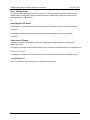
data packet sent from the device to the master. If a data byte is 0xC0, it is replaced by 0xDBDC. If it is
0xDB, it is replaced with 0xDBDD. The conversion is done before transmission. See sample code below.
B.1.5 CRC-8
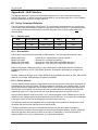
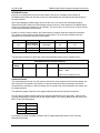
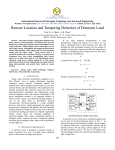
An 8-bit cyclic redundancy check (CRC-8) calculated over the Data packet is embedded in the packet.
8
2
The CRC-8 represented by the polynomial, C(x) = x + x + x + 1.
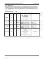
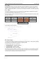
After the computation of CRC, Data packet and CRC-8 is encoded with the special SLIP character codes
described in Section 2.2.
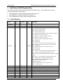
Start
Device Address
Data
CRC-8
End
“C0”
XX
XX… XXn
XX
“C0”
1Byte
1Byte
Variable, nBytes
1Byte
1Byte
Offset = 0
Offset = 1
Offset = 2
Offset = n+2
Offset = n+3
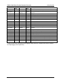
SLIP character codes
Code snippet for CRC-8 calculation:
uint8_t crc8( uint8_t inCrc, uint8_t inData )
{
uint8_t i,crc;
crc = inCrc ^ inData;
for ( i = 0; i < 8; i++ )
{
if (( crc & 0x80 ) != 0 )
{
crc <<= 1;
crc ^= 0x07;
}
else
crc <<= 1;
}
return crc;
}
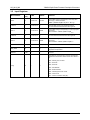
B.2 Packet Types
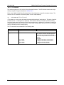
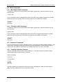
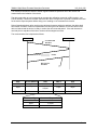
The master shall broadcast a command packet addressed to a specific device. And the device shall reply
by transmitting an ACK/NACK packet followed by a response packet.
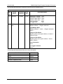
The different packet types can be classified as.
•
•
•
ACK/NACK Packet – Handshake mechanism.
Command Packet – Operational phase.
Response Packet – Reply to the command.
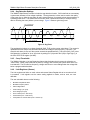
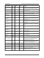
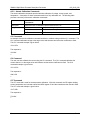
After sending the command packet, the master must wait for a response from the device before sending
out the next command packet. In the case of a non-responsive device, a time-out shall be activated by
the master before re-sending the command packet to the device.
32
Rev. 2