1
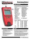
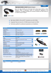
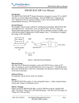
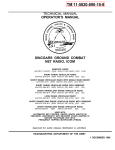
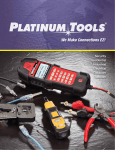
outlined
®
Voice, Data and Video Tester
Instruction Sheet: P/N T119
GENERAL SPECIFICATIONS
•Dimensions:
6.4˝ x 2.8˝ x 1.4˝ (16.3 x 7.1 x 3.6 cm)
IN T
MAD
E
HE
IN TH
E USA
MADE
The Platinum Tools, VDV MapMaster™ is a portable voice-data-video
cable tester. It tests and troubleshoots RJ11, RJ12, RJ45 and F-conector
terminated cables and provides built-in tone generation for cable tracing.
•Weight: 9.0 oz. (256 grams) with battery and remote
US
A
•Operating Temperature: 0˚C/32˚F to 50˚C/122˚F
•Humidity: 10% to 90%, non-condensing
•Maximum Voltage between any two connector pins without damage:
RJ Jack: 66V DC or 55V AC
F-Connector: 50V DC or AC
•Battery Life: 9V alkaline battery typical
Standby: 4 years
Active: 425 hours
•Cable Types: Shielded or Unshielded; Cat7, Cat6x, Cat5e,
Cat5, Cat4, Cat3, Coax
•Maximum RJ Cable Length: 0 to 1,000 feet (305 meters)
•Minimum Cable Length for Split Pair Detection:
1.5 feet (0.5 meters)
•Maximum Coax Cable Length:
Coax Type
Belden P/N Center + Shield Maximum Length
RG-58A/U
8259
9311
7806A
14.9Ω / 1,000 ft
25.8Ω / 1,000ft
11.8Ω / 1,000ft
6,710ft (2,045m)
3,876ft (1,182m)
8,475ft (2,583m)
RG-59/U
9310
9259
8241A
9275
9659
24.1Ω / 1,000ft
23.5Ω / 1,000ft
49.7Ω / 1,000ft
78.5Ω / 1,000
17.6Ω / 1,000ft
4,150ft (1,265m)
4,255ft (1,297m)
2,010ft (613m)
1,275ft (389m)
5,682ft (1,732m)
RG-6/U
1694A
1152A
7.2Ω / 1,000ft
29.8Ω / 1,000ft
13,889ft (4,234m)
3,360ft (1,025m)
Mini Coax
9221
111Ω / 1,000ft
900ft (275m)
RG-11/U
1523A
15.1Ω / 1,000ft
6,623ft (2,019m)
BATTERY REPLACEMENT
WARNINGS
1) Remove single screw in the middle of the back of the VDV MapMaster™ with a #1 Phillips head screwdriver. Remove the battery door.
To ensure safe operation and service of the tester, follow these instructions.
Failure to observe these warnings can result in severe injury or death.
2) Remove the old battery and disconnect
battery cable.
3) Replace with an ANSI 1604A, 9 volt alkaline battery (Energizer 522, Duracell Mn1604). Reattach cable and insert into battery compartment.
4) Replace battery door and screw.
DO NOT OVERTIGHTEN!
1
•The VDV MapMaster™ is designed for use on unenergized cabling
systems. Connecting the VDV MapMaster to live AC power may
damage it and pose a safety hazard for the user.
•Poorly terminated RJ plugs have the potential to damage the jacks on the
VDV MapMaster™. Visually inspect an RJ plug before inserting it into the
tester. The contacts should always be recessed into the plastic housing
of the plug. Plugging 6-position plugs into the 8-position jack on the
tester has the potential to damage the outermost contacts of the jack
unless the plug is specifically designed for that purpose.
www.platinumtools.com
©2011 Platinum Tools Inc. All rights reserved. 1/11
4)
DISPLAY
5) Tester-End Wire Map: The top line displays the pins on the
tester end in order. These pins are mapped to the pins on the
remote-end shown directly below them on the LCD.
1
2
3
4
5
6
7
8
9
1) Mode: The top line displays the cable type test mode or tone generation mode.
2)
Pass/Special Cables: “Pass” will be on if the cable is a properly wired 4-pair T568A/B data cable, a 3-pair one-toone wired voice cable or a video cable with no faults. In
addition, “X-over” illuminates if a properly wired cross-over (uplink) cable is recognized or the “Rev” illuminates if the
cable is a properly wired reverse-pinned voice cable.
The wire map will show actual pin connections.
3)
Cable Faults: The “Fail” icon will be on only if the cable is not wired to one of the cabling standards. An open or short error takes precedence over miswires and the appropriate icon(s) illuminates. The “Split” icon illuminates if the designated
pairs are not twisted together in the cable, an AC signal fault.
A
B
C
KEYPAD
D
E
6)
Remote-End Wire Map: The bottom line displays the
corresponding pin on the remote-end. Dash lines on the remote
line indicate short pins. No pin numbers displayed on the
remote line are open pairs.
7)
Battery Low: The battery low symbol illuminates when the
battery is nearing depletion. The symbol will begin to flash when
the battery needs to be replaced. Results may be unreliable at
this point.
8) Location ID: In the video or the ID modes, the “ID” icon will be
on with the number of the remote ID displayed or an error
message of “Open” or “Short”.
9)
Voltage Detected Warning: If voltage is detected on any of the tester connectors, the “Voltage!” icon is turned on. A check for
voltage is performed before each test and if found, no test is
run. The tester should be disconnected immediately from the
source of the voltage.
type button. Pressing the same connector type button again,
will change the pins carrying the tone. Pressing the Tone button will cycle through the available tone cadences. To turn the VDV MapMaster™ off, press the O/ID button. The VDV MapMaster™ will turn off automatically 60 minutes after the last button press. The tone is compatible with analog tone tracers.
E)
Off/ID (O/ID): Pressing O/ID will turn off the VDV MapMaster™
when it is on in any mode. With the VDV MapMaster™ off,
pressing the O/ID button starts the ID test mode. The ID test
mode scans for all possible ID types – voice, video and data.
The “ID” icon and a progression of “o” are displayed on the
bottom line of the display to indicate scanning is active. If no
ID remotes are found, “Open” is displayed. When and ID remote
is found, the connector type and the ID number are displayed.
If multiple ID remotes are found, the ID or fault is displayed in sequence. The test loops continuously until the I/OD button is
pressed or for 5 minutes after last change in ID status.
B)
Voice: Each press of the Voice button causes one test to be
run on the 6-position RJ jack and the results displayed. The VDV MapMaster™ will turn off after 20 seconds automatically. If the button is pressed and held until “LOOP ON” is displayed, tests are run continuously and the display updated until the
O/ID button is pressed or after 5 minutes of no change in results. Continuous mode is useful for trouble-shooting
NOTE
intermittent problems.
Video: Pressing the Video button starts the ID test, testing only for the F-connector, because the video continuity test
is the same as the ID test. The test loops continuously until the O/ID button is pressed or for 5 minutes after the last
change in ID status.
C)
Data: Each press of the Data button causes one test to be run
on the 8-position RJ jack and the results displayed. The VDV MapMaster™ will turn off after 15 seconds automatically. If the button is pressed and held until “LOOP ON” is displayed, tests
are run continuously and the display updated until the O/ID
button is pressed or after 5 minutes of no change in results. Continuous mode is useful for finding intermittent problems.
D)
Tone: When tone is pressed; the VDV MapMaster™ begins
sending an audio tone for the connector last tested with the
pins and cadence previously selected for that connector type.
To change the connector type, press a different connector
A)
2
Shield: “Shielded” illuminates when a shielded data cable is properly connected at both ends. It will be flashing if there is a
short to a wire in the cable along with that pin number and the
“Short” indicator.
The RJ jacks share internal connections so only RJ cable can
be connected at a time for accurate cable test results. However,
an RJ cable and a coax cable may be connected at the same
time. In ID mode, all connectors on the VDV MapMaster™ may
be connected at the same time.
ID/MAPPING
ID/Mapping: Pressing the O/ID button
starts the ID test mode on the VDV
MapMaster™. Review section “E”
under category “KEYPAD”. ID/MAP
up to 19 locations at one time with
numbered custom ID remotes,
whether Voice (RJ12/11), Video (coax)
or Data (RJ45). Place ID remotes at
one end, the VDV MapMaster™ at
the other end and start scanning.
Mode Locator ID #
www.platinumtools.com
©2011 Platinum Tools Inc. All rights reserved. 1/11
MASTER REMOTE
WIRING and DISPLAY EXAMPLES
Properly Wired T568A UTP:
T568A Cable with Split Pairs:
1
2
3
4
5
6
7
8
Properly Wired T568A UTP:
1
2
3
4
5
6
7
8
T568A Cable with Split Pairs:
T568B is electrically identical to T568A, but swaps
the green and orange pairs. Either standard will work
as long as the same standard is used at both ends
of a run or patch cable. Mixing “A” and “B” creates
a cross-over cable.
A common error in building a cable is to put all the pairs
in pin sequence 1-2, 3-4, 5-6 and 7-8. This will produce
the correct continuity, but the pairs are designated to
be on pins 3-6 and 4-5 in the middle of the connector
for compatibility with phone wiring. This wiring error is
only detected by the split pair test since the designated
pairs are not twisted together.
The VDV MapMaster™ Remote
designed for testing both Voice
(RJ12/11) and Data (RJ45) networks.
Patch cables can be tested without
removing the remote from storage.
NOTE: extra master
remotes can be
used simultaneously if mapping
is done first so
each master
remote can be
identified.
Master Remote
used for network
testing.
ACCESSORIES
Additional accessories to help make testing easier.
8
1
8
Coax Remote Set P/N T120C
ID/MAP 19 video (coax) cables
at one time. Numbered custom
F remotes 1 thru 19 for
easy identification.
= FLASHING
1
T568A Cable with a Short and Open:
1
2
3
4
5
6
7
8
X
1
2
3
4
5
6
7
8
T568A Cable with a Short and an Open:
The 1-2 pair pins are shorted together and the 7-8 pair
is open. The pins with the errors are flashing. Dash
lines (-) on the bottom (remote) display line indicate
the short, while no numbers on the bottom line indicate
the open pair.
T568A Cable with a Miswire and
Unrecognized Continuity:
1
2
3
4
5
6
7
8
T568A Cable with a Miswire and
unrecognized Continuity:
1
2
3
4
5
6
7
8
1 and 2 pins on the VDV MapMaster™ are connected to
pins 2 and 1 at the remote-end. The pins with this error
are flashing. The “U” for the remote pin numbers indicates an unrecognizable continuity was detected that is
neither a short or open. An ID remote connected to the
VDV MapMaster™ when in cable test mode would also
show this error.
Data Remote Set P/N T121C
ID/MAP 19 data (twisted pair)
cables or data ports/jacks at
one time. Numbered custom
RJ45 remotes 1 thru 19 for
easy identification.
Master Remote P/N T124C
The replacement Master
Remote(s) can be used as an
extra Master Remote(s) when
testing networks. Map your
network first to help identify
the extra Master Remote(s).
Toner Cable P/N T125C
RJ45/Alligator
Use when shooting tone via
the data port. Cable conductors
are terminated on contact #1
and #2, so program your VDV
MapMaster to shoot tone on
pair 1 and 2.
NO-Fault Cable P/N T126C
7.5” Special
RJ12 to RJ12
The NO-Fault Cable uses
no-fault RJ12 connectors on
both ends to assure no damage
to the RJ45 jacks. It is the
ideal patch cable to use when
mapping or shooting tone.
RJ45 PortSaver P/N 21025
Extend the life of your tester
by using the RJ45 PortSaver
as your sacrificial cable.
This eliminates the wear
and tear from constantly
plugging in and out of
the tester port.
3
www.platinumtools.com
©2011 Platinum Tools Inc. All rights reserved. 1/11