1
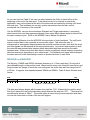
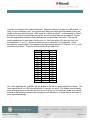
TECHNICAL NOTES: INTERFACING ENCODERS WITH DRIVES & CONTROLLERS
Understanding Binary
Words and the MicroE
Serial Interface Encoder
TN-1301 | REV 151006
TN1301 – MicroE Serial Word
© 2015 MicroE Systems
Introduction
The Mercury™ 3000Si, 3500Si, and Mercury II™ 5800Si and 6800Si are MicroE’s smart
programmable encoder systems with high speed serial word output. Unlike analog or A-quad-B
encoders which must transmit data constantly to the motion controller in order to maintain
accurate position information, the serial word interpolator is always keeping track for you. This
means that the controller need only communicate with the encoder when it actually requires a
position.
SPI Format
Serial Peripheral Interface (SPI) format was developed by Motorola. It is a common and widely
recognized format that is supported by many microprocessor peripheral chips. As its name
implies, it is an interface format not a protocol which means that it simply defines hardware
connections not making any demands on actual binary word format. SPI is a master/slave
arrangement. In our example, the controller is the master and the encoder the slave. At its core,
SPI stipulates 4 wires for basic communication: clock (SCLK), master-out/slave-in (MOSI),
master-in/slave-out (MISO), and chip-select (CS). The master drives the clock and provides the
chip-select signal to activate the peripheral’s ICs. Since in our case, the encoder does not
receive any data from the controller, the MOSI line is eliminated.
M3000Si
The principal limiting factor in A-quad-B encoder speed is how quickly the A and B pulses can
be transmitted. When sensor speed is high and/or the interpolation depth is high, the
quadrature output frequency soon gets beyond the range of most quad-counters and motion
controllers. Since these quad pulses never need to leave the interpolator we’re free to operate
at the sensor head’s full bandwidth all the time. The overwhelming majority of motor controllers
are not equipped, off the shelf, accepting SPI format encoder outputs. As a result, the customer
will typically need a custom design in order to communicate with the encoder system but the
speed/resolution advantage will be significant. The Mercury 3000Si data word is 36 bits long
with 19.5nm resolution (10 bits) and in SPI format. SPI is discussed later in this report. It
supports a maximum clock speed of 10MHz. Factoring in the inherent timing delays, the system
can output a new 36 bit word every 4000ns. This works out to a word rate of 250kHz. The word
is broken down into three distinct sections: 8 bits of status information, an 18 bit fringe counter
and 10 bits of interpolation.
TN1301 – MicroE Serial Word
Page 1
© 2015 MicroE
MSB
LSB
8 bit status
18 bit fringe counter
10 bits of interpolation (x1024)
35 34 33 32 31 30 29 28 27 26 25 24 23 22 21 20 19 18 17 16 15 14 13 12 11 10 9 8 7 6 5 4 3 2 1 0
Table 1: 36 bit data word
Naming the least significant bit “0” tends to make things a little harder to follow but that’s
electrical engineers for you. Working from right to left, the first 10 bits represent the encoder’s
position within one 20µm fringe. 10 bits gives you 1024 different combinations of ones and
zeros starting with 0000000000 and ending with 1111111111. Dividing 20µm by 1024 gives you
19.5nm, the smallest increment of movement the encoder can resolve. Now you need to keep
track of how many fringes the encoder has moved. This leads us to the next portion of the
word, the fringe counter. Once the interpolation section reaches all ones, it reverts back to all
zeros and the fringe counter is incremented by one. The fringe counter is 18 bits long which
gives you the capacity to count up to 262,144. This many increments of 20µm means you can
keep track of a measurement length of up to 5.24m. The remaining 8 bits are called the status
word. Instead of a number, each bit acts as a flag to represent a particular event. Refer to
Table 4 below for the significance of each bit.
The principal limiting factor in A-quad-B encoder speed is how quickly the A and B pulses can
be transmitted. When sensor speed is high and/or the interpolation depth is high, the
quadrature output frequency soon gets beyond the range of most quad-counters and motion
controllers. Since these quad pulses never need to leave the interpolator we’re free to operate
at the sensor head’s full bandwidth all the time. The overwhelming majority of motor controllers
are not equipped, off the shelf, accepting SPI format encoder outputs. As a result, the customer
will typically need a custom design in order to communicate with the encoder system but the
speed/resolution advantage will be significant. The Mercury 3000Si data word is 36 bits long
with 19.5nm resolution (10 bits) and in SPI format. SPI is discussed later in this report. It
supports a maximum clock speed of 10MHz. Factoring in the inherent timing delays, the system
can output a new 36 bit word every 4000ns. This works out to a word rate of 250kHz. The word
is broken down into three distinct sections: 8 bits of status information, an 18 bit fringe counter
and 10 bits of interpolation.
MSB
LSB
8 bit status
18 bit fringe counter
10 bits of interpolation (x1024)
35 34 33 32 31 30 29 28 27 26 25 24 23 22 21 20 19 18 17 16 15 14 13 12 11 10 9 8 7 6 5 4 3 2 1 0
Table 2: 36 bit data word
TN1301 – MicroE Serial Word
Page 2
© 2015 MicroE
Naming the least significant bit “0” tends to make things a little harder to follow but that’s
electrical engineers for you. Working from right to left, the first 10 bits represent the encoder’s
position within one 20µm fringe. 10 bits gives you 1024 different combinations of ones and
zeros starting with 0000000000 and ending with 1111111111. Dividing 20µm by 1024 gives you
19.5nm, the smallest increment of movement the encoder can resolve. Now you need to keep
track of how many fringes the encoder has moved. This leads us to the next portion of the
word, the fringe counter. Once the interpolation section reaches all ones, it reverts back to all
zeros and the fringe counter is incremented by one. The fringe counter is 18 bits long which
gives you the capacity to count up to 262,144. This many increments of 20µm means you can
keep track of a measurement length of up to 5.24m. The remaining 8 bits are called the status
word. Instead of a number, each bit acts as a flag to represent a particular event. Refer to
Table 4 below for the significance of each bit.
Bit
28
29
30
31
32-35
Name
redAlarm
yellowAlarm
indexMode
indexWindow
reserved
Description
Normally 1, 0 if sensor signal low
Normally 1, 0 if signal is near low
Normally 0, 1 if in Cal mode
Normally 0, 1 if within IW
Table 3: Status word
Should a particular application require less interpolation, simply clock out fewer than 36 bits.
Since the MSB is sent first, if you only use 35 clock pulses you will omit bit 0, effectively getting
9 bits of interpolation or x512. Omitting bits 0 and 1 yields 8 bit interpolation or x256 and so on.
This technique need not be limited to just the interpolation bits. If, for whatever reason, you
need less than 20µm resolution, you can start ignoring fringe counter bits as well. While the
M3000 quadrature encoder allows you to select any integer value between 4 and 1024 for your
interpolation depth, the M3000Si limits you to binary steps (x1024, x512, x256, x128, x64, x32,
x16, x8 and x4).
The M3000Si offers two different ways for the controller to request data: the Standard approach
and the Trigger approach. The Standard approach involves using a simple chip-enable signal
which we call n_spiEnable. When this normally high signal is asserted low, the clock (spiClock)
signal toggles out the status and position word until n_spiEnable returns to high. The
uncertainty between the request and the actual measurement is 208ns. If one should need to
synchronize a measurement to an external event with greater precision, they can use the
Trigger approach. Using this separate signal called spiTrigger, a measurement can be
synchronized to within 20ns of the request. The word, however, will take the usual amount of
time to be clocked out. The M3000Si User’s Manual offers a more detailed description of each
approach with timing diagrams and delay specifications.
TN1301 – MicroE Serial Word
Page 3
© 2015 MicroE
Index Modes
There is no index pulse output by the Si encoder system. Basically it serves no external
purpose because the interpolator is generating the position not the controller. This does not
mean, however, that the index becomes unnecessary. One still needs to have a reference
position and the ability to zero the counter. The Si encoders (both M3000Si and M3500Si) offer
five different ways for the index and the position word to interact.
• No Index simply means that there is no interaction. Passing over the index mark
makes no change what so ever to the position word. It should be noted though, that the
status bits will still tell you when the sensor is within the index window as is the case in
any index mode.
• Mode 1 will zero the 18 bit fringe counter upon the first encounter with the index mark
after power-up. The interpolation bits will remain unchanged.
• Mode 2 will zero the fringe counter every time the index mark is seen. Again, no
change to the interpolation bits.
• Mode 3 will zero the fringe counter like Mode 1 and will also subtract out the index’s
inter-fringe position making the output word all zeros (not including status). Internal to
the encoder system, the interpolation bits cannot be zeroed because you cannot
change where you are on the lissajous circle. A useful analogy is that you can easily
forget how many mountains (fringes) you’ve climbed in the past but you cannot ignore
where you are on the mountain you’re currently climbing. Since the index position can
be anywhere within one fringe, that number between 0 and 1024 needs to be
subtracted from the output in order to truly get all zeros.
• Mode 4 behaves like Mode 2 with the index position subtracted out. Any of these
modes can be either factory set or programmed via the SmartSignal™ software.
(NOTE: Mode 5 mentioned in earlier manual versions was in error and is not available)
M3500Si
The Mercury 3500Si encoder offers a 38 bit word with up to 4.88nm resolution (12 bits) and a
few more programmable options. It supports a maximum clock speed of 20MHz. Table 5
shows the data word broken down into its two different possible formats.
MSB
LSB
8 bit status
18 bit fringe counter
12 bit interpolation (x4096)
37 36 35 34 33 32 31 30 29 28 27 26 25 24 23 22 21 20 19 18 17 16 15 14 13 12 11 10 9 8 7 6 5 4 3 2 1
18 bit fringe counter
12 bit interpolation (x4096)
8 bit status
0
Table 4: 38 bit data word
TN1301 – MicroE Serial Word
Page 4
© 2015 MicroE
As you can see from Table 5, the user can select whether the 8 bits of status will be at the
beginning or the end of the data word. If the status bits are of no interest in a particular
application, they can be placed at the end of the data word and omitted by clocking out 8 fewer
bits each time. This translates into not only quicker transmission time but also a more
economical use of memory in the controller.
Like the M3000Si, one can choose between Standard and Trigger approaches to requesting
data however this must be programmed ahead of time since either request signal is received on
the same connector pins. Refer to the M3500Si User’s Manual for specifics.
Another major difference from the M3000Si is the provision of clock feed-back. The spiClockIn
signal is looped back to the controller as an encoder output. This allows the user to
compensate for propagation delays between the controller and the encoder since both the clock
and data signals can be sampled at the same physical point. Line drivers and receivers in both
the controller and encoder have inherent delays associated with them as well as the cable
between them. Without clock feed-back there could be a significant interval between requesting
data and receiving it depending on your cable length. The fed back clock signal will be delayed
the same amount as the data making it easier to synchronize them to each other.
MII5800Si and MII6800Si
The Mercury II 5800Si and 6800Si interfaces features up to 1.22nm resolution (14 bits) with a
user definable length on the position word. Based on how many inter-fringe bits (resolution) and
fringe-counter bits (range of travel) the user configures, the entire data word can range from 27
to 58 bits. It supports clock speeds between 30MHz and 50MHz. Table 6 shows the data word
format.
MSB
Start Bits
1 0 1 1
LSB
Position Word
4-35 Bits
IW
RL
LL
Status Bits
Y
R
S
C
Sp
0
CRC Word
6 Bits
Stop Bits
5 2 1 0
Table 5: 38 bit data word
The data word always begins with the same four start bits: 1011, followed by the position word,
then the 9 status bits, the cyclic redundancy check bits and the stop bits: 1011. The status bits
are defined as shown in Table 7. These bits will be all zeros during normal operation and when
not over the index mark or either of the two limit regions.
TN1301 – MicroE Serial Word
Page 5
© 2015 MicroE
Status Bit
ID
Definition
IW
RL
LL
Y
R
S
C
Sp
Ø
Index Window
Right Limit
Left Limit
Yellow Alarm
Red Alarm
Saturation Alarm
Communication Error
Over-Speed Alarm
Reserved bit is always zero
Active when the sensor is over the optical index mark
Active when the sensor is over the right limit marker
Active when the sensor is over the left limit marker
Active during marginal alignment to the main track
Active during poor or bad alignment to the main track
Active if the main track signal is too large
Active if there is a communication error internal to the encoder
Active if the encoder exceeds 10m/s (the speed alarm threshold)
Table 6: Status bits
The CRC bits are a 6 bit polynomial equal to X6 + X + 1. Like the M3500Si, the MII5800Si and
MII6800Si provide clock feedback to the controller. The encoders can be set to reset the
position to 0 every time the index is crossed (“Index Mode 1”) or to use the position at power up
as the 0 position (“Index Mode 0”).
Both encoders are also available with Panasonic serial interface for integration with a Panasonic
motor controller/amplifier. For more detailed information and timing diagrams, please refer to
the MII5800 or MII6800 series installation manuals.
TN1301 – MicroE Serial Word
Page 6
© 2015 MicroE
Appendix
Binary Words
In an effort to make this Applications Note useful to a broad range of readers with a variety of
skill levels, an overview of binary or digital communication seems appropriate. Binary is a
numbering system consisting of only ones and zeros. In the decimal (base ten) system, which
we’re all accustomed to, any single digit in a number can range from 0-9. Binary (base two)
limits your possible choices to either 0 or 1. This limitation makes binary ideally suited for
electronic counting. Each digit or bit can now be defined electrically in terms of 1 being “on” or 0
being “off”. In the case of TTL (transistor-transistor logic), “on” = +5 Volts and “off” = 0 Volts.
That being said, how do we count in binary? Each digit in a decimal number represents a power
of 10. As an example, the number 247 can be expressed as (2 x 10²) + (4 x 101) + (7 x 100) or
200 + 40 + 7. In binary each digit represents a power of 2. The binary number 100111 can be
expressed as follows:
(1 x 25) + (0 x 24) + (0 x 23) +(1 x 22) +(1 x 21) +(1 x 20) or 32 + 0 + 0 + 4 + 2 + 1 = 39.
All these ones and zeros flying around in say your computer need to be organized into packets
representing a meaningful number. These packets are called words. The number of bits in
each word is typically defined by the individual system. In the case of the M3000Si and
M3500Si encoders, each word is 36 bits and 38 bits long respectively. Table 1 contains each
possible Binary number in a 4 bit long word and its decimal equivalent. Note that it is useful to
show the zeros at the beginning of the smaller numbers so that the full length of the word is
always clear.
Binary
0000
0001
0010
0011
0100
0101
0110
0111
1000
1001
1010
1011
1100
1101
1110
1111
Decimal
0
1
2
3
4
5
6
7
8
9
10
11
12
13
14
15
Table 7: 4 bit binary numbers
TN1301 – MicroE Serial Word
Page 7
© 2015 MicroE
How about counting in the negative direction? Negative numbers in binary is a little trickier. In
order to count down past zero, your system must have two things specified ahead of time: the
length of the word and the format. One format is to define a sign bit. In the example in Table 2,
the last bit on the left is defined as the sign bit: zero for positive and one for negative. Notice
that the magnitude increases in both directions as you get further from 0000. The sign bit
merely keeps track of what side of zero you’re on. Note that with a 4 bit word you can only
count between +7 and –7. Another possible format is called the 2’s complement. In this
arrangement, passing 0000 in the negative direction causes the word to “flop over” to 1111 and
decrement from there. This is the format that the Si encoders use.
Sign Bit
Decimal
2's comp.
0111
7
0111
0110
6
0110
0101
5
0101
0100
4
0100
0011
3
0011
0010
2
0010
0001
1
0001
0000
0
0000
1001
-1
1111
1010
-2
1110
1011
-3
1101
1100
-4
1100
1101
-5
1011
1110
-6
1010
1111
-7
1001
Table 8: Negative counting
The “most significant bit” or MSB is the bit farthest to the left in a word regardless of length. The
“least significant bit” or LSB is the bit farthest to the right in a word. This makes intuitive sense
since changing the bit at the right end from a one to a zero or vice-versa will make only a small
change to the resulting number while changing the left hand bit in a similar fashion will make a
more significant change.
TN1301 – MicroE Serial Word
Page 8
© 2015 MicroE
Transmitting Words
In some systems, words are transmitted in parallel meaning that an eight bit word is sent all at
once on eight different wires. Parallel communication is very fast since the whole word arrives
at the receiver at the same instant. As the length of the word increases, though, this becomes
less and less practical. Imagine an M3500Si needing 38 individual signal lines! As an
alternative, each bit can be sent out over a single line one at a time. This is called serial
communication. While this scheme greatly simplifies your hardware set-up (one wire vs. many),
it is at the expense of transmission speed since the receiver must wait for each bit to arrive
sequentially. Serial communication requires a timing scheme to govern how quickly and at what
interval each bit is transmitted. The signal that does this governing is a simple square wave that
never changes, appropriately called the clock. If the number being sent has two or more zeros
in a row, how do I tell the difference between them? Am I receiving a series of zeros or just one
big long zero? The clock tells me. Each pulse of the clock sends out one bit of the word. If I
read zero at the receiver for a time span of three clock pulses, I know I’ve just received three
zeros in a row.
Now that this word is being sent out a bit at a time, the receiver needs to reassemble these bits
back into the original number. In order to do that, the receiver needs to know in what order they
are being sent. This too needs to be defined ahead of time. All of MicroE’s Si encoders clock
data out with the MSB first.
Word Examples
As a practice exercise in decoding binary words, consider the following examples:
1) M3500Si 38 bit word with the status bits at the end (format 1)
00010000011000000110000100011000000010
•
First let’s add some slashes to help distinguish the three portions of the word
000100000110000001/100001000110/00000010
• The first 18 bits are fringe counter and converting it to decimal gives us
214+28+27+20= 16384+256+128+1=16769. 16769x20µm=335,380µm
• The next 12 bits are interpolation and can be thought of as a “fraction of a fringe”
211+26+22+21=2048+64+4+2=2118. 20µm x(2118/4096)=10.34µm
• Total distance is the sum of the two or 335,390.34µm
• The last 8 bits are the status. Refer to Table 4 for the meaning of each bit.
Normal operation is 00000011 so 00000010 means the red, “signal low” flag is active.
TN1301 – MicroE Serial Word
Page 9
© 2015 MicroE
2) M3000Si 36 bit word
000001110010010000011000011010001001
•
•
•
•
•
Separating the word into appropriate sections gives: status/fringe counter/interpolation
00000111/001001000001100001/1010001001
Decoding the status 00000111 tells us we are in the “Cal” mode
The fringe counter yields 215+212+26+25+20=32768+4096+64+32+1=36961.
36961x20µm=739,220µm
The interpolation gives us 29+27+23+20=512+128+8+1=649. 20µm
x(649/1024)=12.67µm
Total distance is 739,220+12.67=739,232.67µm
TN1301 – MicroE Serial Word
Page 10
© 2015 MicroE