1
A D V A N C E
I N F O R M A T I O N
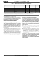
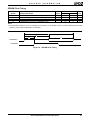
CAPACITANCE
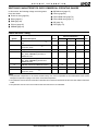
Non-PCI Interface Pin Capacitance
Advance Information
Symbol
CIN
Parameter Description
Test Conditions
Input capacitance
FC=1 MHz
Min
Max
Unit
—
10
pF
C32KXTAL
32KXTAL1, 33KXTAL2 pin capacitance
—
20
pF
C33MXTAL
33MXTAL1, 33MXTAL2 pin capacitance
—
15
pF
COUT
Output capacitance
—
10
pF
CIO
I/O pin capacitance
—
10
pF
PCI Interface Pin Capacitance
Derating Curves
Pin capacitance values are specified in the PCI Local
Bus Specification, Revision 2.2, section 4.2.2.1 DC
Specifications, Table 4-3: DC Specifications for 3.3V
Signaling.
All programmable I/O pins can be driven to the maximum drive current at once.
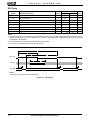
Crystal Capacitance
The crystal specifications can be found in Table 8,
“32.768-kHz Crystal Specifications” on page 42 and
Table 9, “33-MHz Crystal Specifications” on page 42.
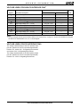
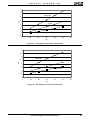
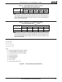
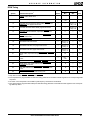
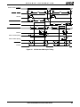
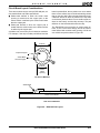
The derating curves on the following pages can be
used to determine potential specified timing variations
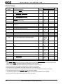
based on system capacitive loading. Table 19, “Pin List
Summary,” on page A-7 has a column named “Max
Load (pF).” This column describes the specification
load presented to the specific pin, when testing was
performed, to generate the timing specification documented in the AC Characteristics section of this data
sheet.
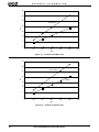
If the capacitive load on GPA0 is 70 pF, then a typical
rise time is 6.5 ns. From Figure 18, the same load gives
a typical fall time of 7 ns.
Élan™SC520 Microcontroller Data Sheet
51