1
Self-Energy Sensors
Research and Development of a Prototype Self -Powered Sensor Platform for Remote
Roadside Monitoring Applications
SUBMITTED IN FULFILLMENT OF THE
Major Qualifying Project
DEGREE REQUIREMENT FOR WORCESTER POLYTECHNIC INSTITUTE
BY
Mark A. Zayac
Ryan J. Thornhill
Ryan D. Welch
(Lifeng Lai, Advisor)
ON
March 27, 2015
Abstract
The Wind Reaper is a prototype for a highway-based sensor platform that powers itself by
collecting energy from passing cars (via a vertical-axis wind turbine) and the sun (via a photovoltaic
module). The system utilizes an ultra-low-power microcontroller to collect and process data from userconfigurable sensors. The collected data is transmitted wirelessly at specified intervals throughout its daily
operation. The system is also capable of detecting abnormal readings and signaling their occurrence with
an “emergency” transmission. The Wind Reaper is intended to be the base for future research and
development into applications for self-energy sensors.
ii
Executive Summary
The Wind Reaper is a prototype for a highway-based sensor platform that powers itself by
collecting energy from passing cars (via a vertical-axis wind turbine) and the sun (via a photovoltaic
module). It was developed as a result of extensive research in the areas of energy harvesting techniques and
remote sensing applications; examples found in research include: solar-powered deep-sea tsunami
detectors, wildfire detectors powered parasitically through the metabolism of trees, and roadside sensors.
The results of this research lead to a set of project requirements that govern the development of the prototype
system.
The system is intended to operate in the median of a busy highway. Because of this, the primary
power sources of the system are a photovoltaic module and a Savonius-type vertical-axis wind turbine. The
particular model of turbine was chosen because it was hypothesized that a Savonius rotor would be able to
efficiently utilize two opposing streams of wind that would result from traffic passing in both directions.
Both primary sources charge a secondary battery that will provide a constant power supply when one or
both primary supplies are inactive. The battery implements a charge controller with electromagnetic relay
that prevents overcharge.
Sensor data is collected by an ultra-low-power microcontroller that is powered by the battery. The
system can interface with any sensor within the design specifications (a simple photodiode was used for
testing). Readings from the sensor are taken periodically throughout the daily operation of the system. Data
is stored in a local buffer and transmitted via a wireless module to an off-site receiver. The system is also
capable of detecting unusual measurements from the sensor; this ability is intended to notice sudden
changes in the roadside environment. In this event, the system immediately transmits the buffer as a sort of
emergency signal.
iii
Acknowledgements
The authors would like to acknowledge the following individuals and thank them profusely for
their support of this project:
Bob Boisse, ECE Shop
Bill Appleyard, ECE Shop
Lifeng Lai, Advisor
Yehia Massoud, ECE Department Head
iv
Table of Contents
Abstract ............................................................................................................................................ ii
Executive Summary ........................................................................................................................ iii
Acknowledgements ......................................................................................................................... iv
Table of Figures ............................................................................................................................. vii
Table of Tables ............................................................................................................................... ix
1
INTRODUCTION .................................................................................................................... 1
1.1
Motivation ......................................................................................................................... 1
1.2
Beginning Ideas................................................................................................................. 3
Tsunami Detection ....................................................................................................... 3
Wildfire Detection ....................................................................................................... 4
Bridge Monitoring ....................................................................................................... 6
Criteria ......................................................................................................................... 7
2
1.3
Our Project ........................................................................................................................ 7
1.4
Existing Products and Patents ........................................................................................... 8
METHODOLOGY.................................................................................................................... 9
2.1
System Requirements ........................................................................................................ 9
2.2
Components .................................................................................................................... 10
Solar Panel ................................................................................................................. 10
Wind Turbine ............................................................................................................. 12
Generator.................................................................................................................... 17
v
Microcontroller .......................................................................................................... 18
XBee .......................................................................................................................... 23
Sensor......................................................................................................................... 26
Battery and Charge Controller ................................................................................... 27
3
IMPLEMENTATION ............................................................................................................. 31
3.1
Hardware ......................................................................................................................... 31
3.2
Software .......................................................................................................................... 38
Microcontroller: MSP430F5529LM .......................................................................... 38
XBee Wireless Module .............................................................................................. 46
4
5
RESULTS ............................................................................................................................... 52
4.1
Characteristics of the ALT10-12P .................................................................................. 52
4.2
Power Generation Based on Car Speed .......................................................................... 60
4.3
XBee Transmission Range: Stationary ........................................................................... 62
4.4
XBee Transmission Range: Drive-By ............................................................................. 62
4.5
Summary of Results ........................................................................................................ 63
CONCLUSION ....................................................................................................................... 64
5.1
Summary ......................................................................................................................... 64
5.2
Project Recommendations............................................................................................... 64
Bibliography .................................................................................................................................. 67
Appendix A: main.c ....................................................................................................................... 70
Appendix B: ALT10-12P Indoor Test Data ................................................................................... 75
vi
Table of Figures
Figure 1-1: Overview of US Energy Consumption by Source and Sector, 2013............................. 2
Figure 1-2: Individual servicing Tsunami sensor buoys [4] ............................................................ 4
Figure 1-3: Voltree Bioenergy Harvester......................................................................................... 5
Figure 2-1: Monocrystalline (left) and Polycrystalline (right) PV Modules.................................. 11
Figure 2-2: ALT10-12P Polycrystalline Photovoltaic Module ...................................................... 12
Figure 2-3: Turbulence Models of Modern Horizontal and Giromill Wind Turbines ................... 13
Figure 2-4: Visual Comparison of Vertical- and Horizontal-Axis Wind Turbines........................ 14
Figure 2-5: Darrieus Wind Turbines With Savonius-Type Start-Up Rotors ................................. 15
Figure 2-6: Effects of Offset Blades in a Savonius Rotor .............................................................. 16
Figure 2-7: Flow Diagram Showing Single-Channel Mode .......................................................... 20
Figure 2-8: XCTU User Interface .................................................................................................. 26
Figure 2-9: Schematic for a Battery Charge Controller ................................................................. 30
Figure 3-1: Top View of Turbine Showing Lock Block and Adjustable Mountings .................... 31
Figure 3-2: Adjustable Feet of the Wind Turbine Frame ............................................................... 32
Figure 3-3: Battery and Circuitry Mounted in Turbine Frame ...................................................... 33
Figure 3-4: Shaft Collar Connecting the Turbine and the Generator ............................................. 34
Figure 3-5: Battery Terminal Connectors ...................................................................................... 34
Figure 3-6: Safety Tubing for Power Cable from PV Module....................................................... 35
Figure 3-7: Cable Connector to be Attached to DC Generator ...................................................... 36
Figure 3-8: Break-Out View of Charge Controller and Circuitry .................................................. 37
Figure 3-9: Top View of Assembled Circuitry .............................................................................. 37
Figure 3-10: State Diagram for Microcontroller Logic.................................................................. 39
Figure 3-11: Example of an Emergency Buffer Stored in Memory ............................................... 41
Figure 3-12: One Buffer of ADC Samples Stored into the Flash Memory.................................... 43
vii
Figure 3-13: Evidence that All Four Memory Banks Have Been Erased ...................................... 43
Figure 3-14: Oscilloscope Reading Showing Transmission of Data on the TX Pin ...................... 45
Figure 3-15: XCTU Interface with No Radio Modules Connected ............................................... 47
Figure 3-16: XCTU Interface: Adding a Device ........................................................................... 48
Figure 3-17: XCTU Interface: Configurable Parameters ............................................................... 49
Figure 3-18: XCTU Interface: Addressing Fields.......................................................................... 50
Figure 3-19: XCTU Interface: Data Visualization Console ........................................................... 51
Figure 4-1: Indoor Test Environment for the PV Module ............................................................. 53
Figure 4-2: Power and Voltage Plotted Against Resistance .......................................................... 54
Figure 4-3: Power and Voltage Plotted Against Resistance (Scaled Axis) ................................... 54
Figure 4-4: Power Plotted with Trend Line Against Voltage ........................................................ 55
Figure 4-5: Evaluating the Local Maximum of the Power Curve .................................................. 56
Figure 4-6: Comparison of Power Vs Load Curves in Different Light Environments .................. 57
Figure 4-7: Cardboard Cover in Position 3 .................................................................................... 58
Figure 4-8: Outdoor Environment for Testing the PV Module...................................................... 59
Figure 4-9: Indoor Versus Outdoor Power Characteristics ............................................................ 60
viii
Table of Tables
Table 2-1
Electrical Specification of the XBee Wireless Module .............................................. 25
Table 2-2: Comparison of Battery Characteristics by Chemical Composition .............................. 28
Table 4-1: Data Regarding Road Simulation Testing .................................................................... 61
ix
1 INTRODUCTION
In this section, we discuss our motivation to create a remote sensing unit that is powered using
renewable energy. We describe the flow of ideas in chronological order that gave us incite on our final
design. We then describe our project and detail the criteria we extrapolated from our background research.
Finally we mention existing products and patents that are relevant to our project.
1.1 Motivation
Many fields of science and technology are dedicated to monitoring our world. Some of these fields
are on the cutting edge of technology and use sophisticated equipment to remotely monitor dangerous
environments. For example, the health of agricultural crops can be measured by autonomous drones
equipped with infrared cameras [1] and devastating tsunamis can be detected hours ahead of landfall by
deep-sea underwater pressure sensors. In both cases, remote technology can dramatically improve the
accuracy of data while simultaneously reducing maintenance costs and risks posed to humans by dangerous
and demanding tasks.
Yet there are still environments in this modern world of ours that lack this important technology.
Most instances of wildfire detection are still conducted entirely by human observers, and the structural
health of many bridges is still monitored in person. In these fields, the accuracy of the data collected is still
prone to human error and the environments are in many ways dangerous to humans. For this reason, we
sought to design a remote monitoring system that would be entirely self-sufficient in order to significantly
reduce its need for human interaction after being installed.
Remote sensors in many systems are powered by either long-life batteries or the public electrical
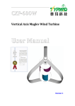
grid. While batteries are an appropriate power source for short-term systems, permanent installations mostly
rely on commercial power. 88% of all electric power generated in the United States comes from nonrenewable sources (oil, coal, natural gas, and nuclear fuels) [2].
1
Figure 1-1: Overview of US Energy Consumption by Source and Sector, 2013
In recent years, social awareness of non-renewable fuel sources and their harmful effects on our
environment have driven the development of energy efficient and environmentally friendly systems.
However, without a suitable replacement for non-renewable fuel sources, energy efficiency only prolongs
the inevitable end of the earth’s supply of coal, oil, natural gas, and nuclear fuels. For this reason, we were
motivated to make our system rely on renewable energy sources.
To further reduce our impact on the environment and the economic costs associated with system
maintenance and replacement, we strived to create a product with a theoretically infinite lifespan.
Unfortunately, many factors play into the actual longevity of any design. Every component of any design
2
has a practical lifespan. To further realize our goal of designing a self-sufficient sensor system, we aimed
to use components that will operate effectively for as long as possible and will be recyclable at the end of
their life.
Overall, we decided to pursue a design that would fill a gap in remote sensing technology and
ultimately prove the feasibility of implementing renewable and environmentally friendly energy sources in
daily applications.
1.2 Beginning Ideas
The following sections explain the first ideas we had for the project in chronological order. Each
idea helped lead to our final project idea, and gave us insight on possible parameters for our project.
Tsunami Detection
One idea was to use wave energy to power sensors in tsunami detection systems. Tsunami detectors
are water pressure sensors that are sunk to the bottom of the sea or suspended at a certain depth. If there is
a certain pressure change in the water, it may be a sign of a possible tsunami. The pressure sensor sends a
signal to an onshore location via an attached buoy platform. As we began to research the idea it became
clear that the sensors were not powered by alternative energy, but instead with a battery. However, we soon
discovered that tsunami detectors were serviced every 2-4 years to replace sensitive parts [3].
3
Figure 1-2: Individual servicing Tsunami sensor buoys [4]
Servicing the sensors is important to keep the accuracy and integrity of the sensor in working
order. It is useless to develop a long-term self-sufficient power source because the battery can be replaced
during biennial maintenance. As a result we decided to forgo the idea of designing a tsunami warning
system.
Wildfire Detection
Wildfire detection is currently on the rise in the United States due to the increase of intensity and
frequency of fires in recent years. In 2007, more than $2.5 billion of damage was done by wildfires. Modern
wildfire technology is quickly advancing to implement ground sensors that can remotely detect smoke and
heat signatures. Surprisingly, the current most viable method is a watch tower where a trained worker keeps
4
an eye out for smoke and flame [5]. An application of remote sensing can cover a vast area of forest without
increasing the cost and maintenance of the sensors [6, pp. 7-8]. Therefore, using sustainable energy would
be an excellent idea for this type of application.
Unfortunately, there is not a consistent power source that would be able to run a low power device.
Sunlight and wind would not be reliable energy sources due to the sensor being on the ground floor of the
forest. A piezoelectric energy harvester uses a flexible membrane which converts mechanical vibrations
into electrical power. In this case the vibrations would come from the movement of the tree, which would
only move during very windy times, and thus were unreliable energy producers.
Trying to find a reliable power source led us to find Voltree, a company that has patented a way to
harvest energy from trees. Voltree creates power from trees by using the PH difference from the tree’s
trunk and the soil, shown in Figure 1-3[7].
Figure 1-3: Voltree Bioenergy Harvester
5
The power generated is very small but provides enough power to run their fire detection product
named the Javelin. The unit can sense many different data points including: humidity, temperature, wind
speed/direction, precipitation, 360° visual fire alert, and more. In addition, the Javelin sends the data
wirelessly to an offsite location [8]. We learned from Voltree that having an environmentally friendly and
sustainable energy source was something that we wanted to include into our project. However, the Javelin
would have been major competition if we decided to enter this market. For this reason, we decided not to
pursue a product in this area.
Bridge Monitoring
In their 2013 Report Card for America’s Infrastructure, the American Society of Civil Engineers
(ASCE) issued a grade of C+ (mediocre) to the category of Bridges. This is largely due to the fact that over
67,000 of the nation’s 607,380 bridges are considered structurally deficient. Furthermore, the report states
that the Federal Highway Administration (FHWA) estimates that spending on bridges must increase by $8
billion annually to “eliminate the nation’s bridge deficient backlog by 2028” [9]. Clearly, bridges are
expensive installations. As bridges age, maintenance costs increase. However, if maintenance is deferred
(as it often is, according to the 2013 Report Card), structural deficiencies worsen and costs are driven up.
Simply put, many bridges in the United States were not regularly serviced, and as a result, small problems
that could have been repaired quickly and inexpensively when they first arose have now developed into
serious structural issues that will take a good deal of time and money to repair.
In the conclusion of the 2013 Report Card, the ASCE proposes solutions that can be immediately
implemented; one such solution is prioritizing bridge repairs based on a risk-prioritization model.
Additionally, one long-term solution proposed by the report is to develop a plan to build more resilient
bridges and make repairs to existing bridges more effective and longer-lasting. In both of these solutions,
holistic bridge health monitoring will play an important role [9].
Evaluating the structural health of a bridge in person is a large and risky undertaking, especially
when structural elements are suspended above or below the roadway. Even if automatic sensors are used
6
instead of humans, such sensors must also be maintained if they are to provide accurate readings. To this
end, we considered the possibility of designing self-sufficient sensors that could be used to monitor bridge
health. A sensor array that harvests energy from its environment would significantly reduce maintenance
requirements by eliminating the need for battery replacement.
In the same 2013 Report Card, American roads received a grade of D (poor) [9]. After considering
the possibility of bridge health sensors that harvest energy, we realized that the same idea could easily be
applied to all roadside sensing applications in general.
Criteria
After extensive research, we recognized our project needs to satisfy three criteria:
Based on our Tsunami research, using sustainable energy will increase the lifespan of the
battery and therefore decrease the frequency of maintenance routines
Based on our Wildfire Application research, the product should be powered in an
environmentally-friendly fashion
Based on our Bridge Monitoring research, the sensors should be self-powered because their
location is inaccessible or dangerous
These three criteria helped determine our final project, which focused on highway applications.
1.3 Our Project
All of these applications were great stepping stones, paving the way for our initial design. Our
project is a wireless self-sufficient sensor platform that is located on the side of the road. Our product will
be located on the median of well-traveled highways, where wind created by high speed traffic will provide
self-sufficient energy via a wind turbine. Sensors monitoring road conditions and atmospheric gases will
be powered by a combination of the turbine and a solar panel. The sensors will collect readings from the
environment at predetermined intervals and data will be stored on site between daily transmissions. The
7
data will be wirelessly transmitted over Wi-Fi to a data logging device, where it can be analyzed and
published. Anomalous data will trigger an immediate “emergency” transmission.
1.4 Existing Products and Patents
Currently there are no commercial products that provide roadside monitoring in the manner that
we are proposing. However, there are technologies on the market that have simila goals. One product, the
AQM 60 Air Quality Monitoring Station by Aeroqual, is a mobile air quality station that can be placed in
many different locations. The product boasts the ability to measure up to 10 different pollutants and
environmental parameters. The AQM 60 uploads all measured data wirelessly in real time, giving an
operator the most up to date information [10]. However, the product does not use renewable energies such
as wind or solar power.
The AQM 60 is the only commercially available monitoring station available on the market at this
time. However, many U.S. patents cover similar aspects of our product. One such patent, US 7427173 B2,
is a roadside wind turbine that utilizes wind energy from cars to power a vertical turbine [11]. The patent
states that the turbine would be located alongside the roadway, or in the middle of a highway barrier.
8
2 METHODOLOGY
In this section, we go through the basic requirements our project will need. After defining these
requirements we look at each individual component of the system, and use these requirements to rationalize
our decision for each component. We also elaborate on the specifications of these chosen components. After
these components are explained, we describe how all the components are combined and applied in the final
prototype. We split this section into hardware and software to separately illustrate the physical prototype
and the data processing coding within.
2.1 System Requirements
As discussed in Section 1.3 (Our Project), we designed and constructed an energy-harvesting sensor
platform that collects and transmits data from a roadside environment. The methods by which the data is
collected can vary by application. Before developing our prototype, we established a set of requirements
and constraints for the design based on intended operating conditions. The system requirements (what the
product needs to do and achieve) set forth in the following sections are also influenced by the three criteria
developed in Section 1 (Motivation).
The System Requirements (SR) are as follows:
SR-1
The system will be located on the highway next to high-speed traffic as to allow
the sensors easy access to the environment.
SR-2
The system itself will be a platform which will interface with third-party sensors
that perform tasks as required by the user.
SR-3
The system will regularly process data from its sensors and periodically transmit
the information wirelessly to a user-specific receiver. The system will also immediately
transmit if it detects values beyond a given threshold (emergency transmission).
SR-4
The system will not create an unsafe driving environment. This limits the size of
the entire system to an area approximately 2 feet wide by 2 feet long by 5 feet tall.
9
SR-5
The system will, in all respects, by environmentally friendly.
SR-6
The budget for prototype development and testing is $375.
SR-7
The system will collect enough energy from its environment to power a data
processor, a wireless transmitter, and an array of sensors.
SR-8
The system will be powered by a sustainable source of energy in order to minimize
the costs associated with regular maintenance.
SR-9
The system will store excess energy, which will serve as a secondary source of
power.
2.2 Components
The following sections will detail all the components of the system. We will describe the
components and give reasons to why we chose them.
Solar Panel
Typical highways are uncovered and are exposed to the open sky, therefor solar power is a readily
available source of energy. Powering our system with a solar panel satisfies SR-5 and SR-8. While the term
“Solar Panel” is a general term that describes a number of panel-like objects that can be used to capture
energy from the sun, most people specifically think of photovoltaic (PV) modules, which is a package of
several connected solar cells. These cells are made of materials like crystalline silicon that produce
electricity when exposed to photons. There are two kinds of crystalline silicon that are used in the
production of solar cells: polycrystalline (p-Si), which results in bright blue, rectangular cells; and
monocrystalline (m-Si), which results in dark blue, octagonal cells.
10
Figure 2-1: Monocrystalline (left) and Polycrystalline (right) PV Modules
PV modules with p-Si cells are less efficient in terms of energy produced per unit area than modules
with m-Si cells, but are also less expensive and more tolerant of low temperatures. Furthermore, PV
modules with m-Si solar cells can face drastic drops in power output if they are partially covered. It was
for this reason in particular that we elected to use a polycrystalline solar panel in our design. A solar panel
in a roadside environment could possibly be subjected to snow, which would render an m-Si panel
inoperable until its surface was fully cleared, whereas a p-Si panel would continue to provide some amount
of power so long as part of its surface was exposed.
PV modules are available in almost any size and their power output is related to their surface area,
so bigger modules produce more power than smaller modules. Note that this is not an exact linear
relationship but instead a general trend because there are many other characteristics that affect the power
output of PV modules, such as their cell configuration and composition. Large PV modules also tend to
come with an equally sizable price tag. Unfortunately, SR-4 limits the size of our system and SR-6 limits
our budget. Because of this, we needed a cost-effective, moderately sized polycrystalline PV module that
could produce a decent amount of power, even in less-than-ideal situations like cloudy days. We bought a
11
suitable module for $40 from altE, a company that specializes in manufacturing “alternative energy”
products. The ALT10-12P (pictured below in Figure 2-2) is 10.8% efficient and has a rated power output
of 10 watts (12 volts). It measures 14.6” x 9.8” x 0.71” and can operate in temperatures between -49° and
185°F. Furthermore, altE specifically promotes the ALT10-12P for use in remote monitoring systems.
Figure 2-2: ALT10-12P Polycrystalline Photovoltaic Module
Wind Turbine
Highways are also excellent sources of wind energy. Their long corridor-like shape funnels wind
like a wind tunnel and high-speed traffic can generate gusts of wind up to 15 MPH. Placing a wind turbine
next to the road to harness this energy would satisfy SR-1, SR-5, and SR-8. Like solar panels, wind turbines
come in many different sizes and configurations. In residential and commercial applications, the most
common configuration has three blades rotating on a horizontal axis mounted on a pole or tower. The
rotation of the axis spins an electrical generator, which is typically positioned immediately behind the
blades. Unfortunately, horizontal-axis wind turbines (HAWTs) require a good deal of clearance to prevent
foreign objects from colliding with the rotating blades. Because of this, a roadside system would not be
able to use a HAWT on account of the risks it would pose to passing vehicles, which violates SR-4.
For many years, people have been concocting alternative configurations for wind turbines, ranging
from niche to wildly impractical. A particularly common theme among these designs in the idea that a
turbine could be powered by the wind generated by passing cars. Because of the matters of space and safety
12
previously mentioned, these hypothetical designs frequently adopt a vertical-axis configuration. The most
significant advantage that vertical-axis wind turbines (VAWTs) hold over HAWTs is that they do not need
to be aimed into the wind, which is useful when the wind is inconsistent. However, VAWTs are less
efficient than their horizontal counterparts because they generate more turbulence, as can be seen by the
models in Figure 2-3 (below).
Figure 2-3: Turbulence Models of Modern Horizontal and Giromill Wind Turbines
When placed in a single stream of wind, VAWTs lose some efficiency because half of their
structure is always rotating into the wind. However, we hypothesized that this particular disadvantage could
be overcome by installing the turbine on the median of the highway. In such a position, the turbine would
have two sources of wind (one from each direction of travel) that would be opposing and theoretically
complementary.
13
Figure 2-4: Visual Comparison of Vertical- and Horizontal-Axis Wind Turbines
VAWTs follow one of two general designs which are named for their respective inventors:
Savonius turbines and Darrieus turbines. Savonius turbines are characterized by having a number of scooplike blades and most modern turbines utilize two or three semi-cylindrical blades. Some turbines use a
twisted Savonius design, which is a variation of the original where the blades take on a helical twist.
Savonius turbines have a low startup speed (meaning that they do not require high wind speed to start
rotation) and are very simple to construct. The Darrieus model of VAWTs has curved, vertical airfoils
mounted around a central axis (this look has earned Darrieus VAWTs the nickname of “eggbeaters”). A
giromill is a variation of the Darrieus turbine with straight instead of curved blades (the second turbine in
Figure 2-3 is a giromill type turbine). Darrieus turbines are more efficient than Savonius turbines, but are
far more complex in their construction because they require airfoil blades. Darrieus turbines also have a
high startup speed and require either an external motor or smaller “startup turbine” to begin rotation (an
example of such a configuration is shown in Figure 2-5).
14
Figure 2-5: Darrieus Wind Turbines With Savonius-Type Start-Up Rotors
We expect that traffic in a typical highway environment will be variable throughout the day. At
some times, traffic will be light and the resulting wind will be minimal, so we decided to use a Savonius
turbine in our system because of its low startup speed. After further research, we discovered that the
efficiency of a Savonius turbine can be increased by offsetting the blades as seen in Figure 2-6. This allows
the air to flow through the structure more easily, which reduces drag. In an interview with Dr. Maria
Chierichetti of Worcester Polytechnic Institute, we learned that the ideal size of this offset (labeled as e in
the figure below) is 20% of the overall diameter (D) of the turbine.
15
Figure 2-6: Effects of Offset Blades in a Savonius Rotor
In general, the power available in wind has a cubic relationship with the speed of the wind. The
following equation describes the available power (in watts) in the wind.
1
𝑃𝑜𝑤𝑒𝑟 = ( 𝜌) (𝐴)(𝑊 3 )
2
Where 𝜌 is the density of air (typically 1.2Kg/m3)
A is the cross sectional area of the turbine (in meters2)
and W is the speed of the wind (in m/s)
Unfortunately, it is theoretically impossible to fully utilize the available power in wind. In 1919, a
German physicist by the name of Albert Betz published findings and calculations regarding the maximum
efficiency of an ideal wind turbine, which has come to be known as the Betz Law. The law is derived from
the principles of conservation of mass and momentum of the air stream and states that no turbine can capture
more than 16/27 (59.3%) of the kinetic energy in wind. The factor 16/27 (0.593) is known as Betz's
coefficient. Practical utility-scale wind turbines achieve at peak 75% to 80% of the Betz limit. This is largely
due to the inherent drag and friction forces that exist in the turbine equipment.
16
Once again, the size of the turbine is limited by SR-4. Dr. Chierichetti also revealed to us that
VAWTs have an ideal diameter-to-height ratio of 1:2. With this in mind, we constructed a prototype turbine
measuring 1’ in total diameter by 2’ tall (this is smaller than the maximum area in SR-4 to allow for a
supporting frame) . The turbine follows the previously discussed Savonius design with two offset blades.
The blades were repurposed aluminium stovepipe pieces, which we used because they were inexpensive,
and already curved (the latter was particularly important during later attempts to build a larger turbine; we
quickly discovered that it is very difficult to apply a uniform curve to large sheets of metal without the
proper equipment). Aluminium is also a lightweight metal that is easy to manipulate. The blades were
mounted to a rectangular piece of acrylic at both their top and the bottom to maintain structural integrity.
When we tried to calculate the power output of the wind turbine, we ran into a problem. Due to the
fact that HAWTs outperform VAWTs in most applications, Savonius turbines are not often the subject of
scientific research and analysis. The findings of studies that have been conducted are inconsistent with each
other. As a result, we were unable to generate a comprehensive calculation to determine the efficiency of
our turbine. Instead, estimated the efficiency based on published measurements of other similar machines.
Overall, we found that Savonius turbines have an efficiency between 20% and 40% of the Betz Limit. We
assumed that our turbine–being a rough prototype designed and assembled by a team with no experience in
the field of aerodynamic machines–would likely fall in the low end of the range. We also decided that it
would be better for us in the long run to perform calculations with pessimistic assumptions (and therefore
design our system around a smaller power budget) in case we found that the actual output was higher (thusly
providing excess power to our design, which would be handled in accordance with SR-9).
Generator
In order to actually utilize the power produced by the wind turbine, we needed a generator to
convert the mechanical energy of the turbine into electrical energy for our system. We elected to use a DC
generator because the PV module also produces DC power. Even small DC generators are expensive
(starting at $100), so in accordance with SR-6, we sought out used electric drills from which we could
remove and repurpose DC motors. DC motors and generators are physically identical and only differ in the
17
fact that motors consume electrical energy to produce mechanical energy and generators do the exact
opposite. Unfortunately, two of the drills that were donated to us ran off of AC power and as a result did
not have motors that could be used as generators. A third drill did contain a DC motor, but after preliminary
testing, we realized that the force required to turn the shaft was impractically high (drill motors are designed
to apply a lot of torque to the drill bit). We eventually borrowed a DC motor from the Electrical Engineering
Workshop at WPI for free. The motor was primarily chosen because it was free and readily available. It has
a rated maximum power of 24 V, but we do not know much more about it because it was manufactured in
1977 and no data sheet could be found.
When calculating the power that we can ultimately extract from the wind, we need to consider the
efficiency of both the wind turbine and the generator. Given the lack of significant data available on both
components, we assume an overall efficiency of 10%.
Microcontroller
The function of our system is to collect data from an array of sensors and wirelessly transmit it to
another location to eliminate the need for human interaction with the unit. The data collection is handled
by an MSP430F5529LP microcontroller on a Launchpad development board (both made by Texas
Instruments). We chose this component for the following reasons:
First, all three members of the project team have experience working with the MSP430 family of
microprocessors. A big step in working with a microcontroller is becoming familiar with the architecture.
Initializing a new board can take time, especially if the engineer is unfamiliar with the board.
Secondly, the chips in the F55xx class of the MSP430 are specifically designed to be used in “ultralow-power” applications. With a rated power consumption of 290 μA/MHz at 8MHz when fully active
and 2.1 μA/MH in Low Power Mode 3, the MSP430F5529LP easily confines to our strict power budget
in our design [12].
18
Finally, the MSP430F5529LP provided a suitable analog-to-digital converter (ADC),
programmable flash memory, and user asynchronous receiver/transmitter (UART) communication, all of
which are needed in our design. The following sections will detail those features.
2.2.4.1 Analog to Digital Converter - ADC
The MSP430F5529 boasts both a 10-bit and a 12-bit ADC at a speed of 200 kilo-samples per
second (ksps). We decided to go with the 12-bit ADC because it gives us a resolution of 610μV per bit as
compared to the 10-bit ADC resolution of 2441μV. The 12-bit resolution calculation is shown below:
212𝑏𝑖𝑡 = 4096 𝐷𝑖𝑣𝑖𝑠𝑖𝑜𝑛𝑠
𝐹𝑢𝑙𝑙 𝑠𝑐𝑎𝑙𝑒 𝑟𝑎𝑛𝑔𝑒 = 2.5𝑉 − 0𝑉 = 2.5𝑉
𝑅𝑒𝑠𝑜𝑙𝑢𝑡𝑖𝑜𝑛 =
2.5𝑉
= 610μ𝑉
4096
In other words, 610μV is the smallest voltage change the ADC can detect. The MSP430 has the
ability to set the reference voltage to 1.5V, 2V, or 2.5V. We chose the 2.5V range because it allows us
greater flexibility to add a diverse range of sensors into the network [13].
In our system, the ADC samples at a rate of once every six minutes. At this speed, 240 samples are
collected daily. We chose this sample rate due the available size we had in the flash memory (addressed in
the next section). Every sample from the ADC is a 16-bit unsigned integer and we have 512B of memory
available to store the data in. Although the memory size is our main constraint, sampling more than 10
times an hour would most likely not give us any new information, thus making it an appropriate sampling
rate.
The ADC has four different conversion modes: Single-channel Single-Conversion, Repeat-SingleChannel, Sequence-of-Channels (Autoscan), and Repeat-Sequence-of-Channels (Repeated Autoscan).
Each conversion mode offers a different method for getting the conversion samples. We decided to use
Single-channel mode due its simplicity. In Single-Channel mode, the ADC waits to be enabled by the user.
19
Once enabled it will get one ADC sample buffer and convert it into an integer value. When complete, the
enable bit is automatically set back to zero and waits to be re-enabled by the user. As a comparison, RepeatSingle-Channel mode operates in a similar fashion but with one key difference. Once enabled, the ADC
will repeatedly fill and convert the ADC buffer until a stop bit is enabled. We decided not to use this mode
because we felt we had more control over the ADC in Single-Channel mode by telling it exactly when we
wanted an ADC buffer of new data [13]. A flow diagram of Single-Channel mode is shown below:
Figure 2-7: Flow Diagram Showing Single-Channel Mode
In both the Repeat-Single-Channel and Repeat-Sequence-of-Channels modes (the other two modes
mentioned above), multiple inputs into the ADC can be sampled and converted. It should be noted that this
20
functionality of the ADC could be used for future improvements to the system design to accommodate for
multiple sensor inputs [13].
2.2.4.2 Memory
The MSP430F5529LP flash memory is non-volatile and partitioned into different size segments.
The code memory segments are 32kB while the information memory segments are 128B. Initially we
wanted to use the large code memory banks to store our information but we found that the banks held
important data for our code and would cause the program to crash if erased. As an alternative we decided
to use the information memory. The information memory is segmented into four banks the size of 128B
giving us 512B total. The total size of the bank is sufficient enough for us to store a value every 6 minutes
(as mentioned previously in section 2.2.4.1) [13].
The flash memory default mode is Read mode. In read mode, writing and erasing the memory are
disabled. In order to write to the memory, four steps must be followed in order. To write a segment to the
memory, the watchdog timer must first be disabled. Next the flash controller must be configured in the way
you want it and the WTR bit must be high. After that we can write the data into any memory segment by
providing a pointer to the address. Finally, once the data is written, the WRT bit is set low and the LOCK
bit is enabled. Although it is not illustrated, the LOCK bit must be 0 during the write to memory [13]. The
steps are illustrated below:
Page 347 from the MSP430x5xx Family Users Guide
21
In order to erase data from the flash memory, five steps must be followed in order. First, the
watchdog timer must be disabled. Next, a busy bit needs to be polled until it is set to 0 by the CPU (not user
controlled). Once the BUSY bit is 0, the flash controller needs to be configured properly and set into erase
mode. For the actual ‘erase’ step, we are really writing all 1’s to the memory location. As mentioned before,
all 1’s in a memory segment is a clean slate that can be written to. So, erasing is actually writing over the
old data. Finally, the LOCK bit must be re-enabled [13]. The steps can be seen below:
Page 344 from the MSP430x5xx Family Users Guide
Data can only be written to a bank four times before the memory segment must be erased. Failing
to do so causes the memory segment to display all 0’s because the flash memory can only write 1 to 0
individually and requires an erase function to set them back to 1. The smallest size memory that can be
erased is one segment, which is 128B. Due to this we opted to erase all four information memory segments
at once, once all the information from the memory is sent over the UART [13].
2.2.4.3 Universal Serial Communication Interface - UART Mode
The Universal Serial Communication Interface (USCI) can be set in two different modes, Universal
Asynchronous Receiver and Transmitter mode (UART) and Serial Peripheral Interface mode (SPI). The
main difference between UART and SPI is that UART is asynchronous and SPI is synchronous.
Asynchronous means that the USCI and the peripheral do not need a shared clock in order to operate.
Synchronous on the other hand, does need a synced clock. Due to our interface with the XBee, we did not
need a shared clock, thus choosing UART mode for our USCI. [13]
22
UART mode on the MSP430F5529LM operates using two pins (RxD and TxD) for receiving data
and transmitting data. We were only concerned with the transmission pin (sending the data to the XBee
module). UART mode can operate in 7-bit or 8-bit with odd, even, or non-parity. We chose to operate the
UART in 8-bit mode because the data we are transmitting is a factor of 8 (16-bit integers), which drastically
simplifies the data transmission and receiving. Odd and even parity are very simple ways to check for data
error when using asynchronous communication. In order for it to work, both the transmitting (MSP430)
and the receiving (XBee) need to have the same parity. For simplicity, we decided to choose non-parity and
transmit errors if any arise [13].
Another initialization for the UART mode was the order with which we sent the data: Least
Significant Bit (LSB) first or Most Significant Bit (MSB) first. We opted to use LSB because the XBee
sends/receives in LSB. Having them both be the same would keep our data in the same order, thus making
it easier to interpret and receive.
The final initialization we did for the UART mode was the programmable baud rate. The baud rate
is how fast we are able to transmit/receive the data. The baud rate on the MSP430 can be set to a variety of
different preset values. We chose the value 9600 because that was the default value on the XBee module.
Having the same baud rate will help minimize errors in the Tx/Rx process [13].
XBee
To transmit the data, we chose an XBee wireless module. The XBee is a popular component among
wireless engineers because it is relatively easy to program and operate. When two or more XBees are in a
system, they will automatically connect and communicate with each other making wireless communication
relatively easy. The interface and protocols between these two XBees transmitting and receiving is not
important because two XBees connected in the same system will recognize and connect to a similarly
designed XBee. This means the protocols and interface could be anything as long as the two XBees are the
same, making the data we see on the output of the microcontroller’s UART pin the same data as what the
receiving XBee displays. In this way, the XBee is modular for all sensors and the data the sensors produce.
23
The XBee consumes up to 309mA of current when transmitting, far more than the microcontroller.
This is the main power consumption of the entire system, as wireless transmission usually requires large
amounts of power. However, the XBee consumes very little power when not actually transmitting, as there
are two sleep modes that can be activated by setting a sleep pin. The current is reduced to 2mA in associated
sleep mode and 6µA in deep sleep. In this way we can have the XBee off, charge the battery, and when
enough charge is built up the XBee will turn on and transmit [14].
The XBee is very small (about 1 inch by 1 inch in size) and can send data of 7 or 8 bits at a time,
with the Least Significant Bit first. If our data is of greater size 7 or 8 bits, we can modify the microcontroller
to put different segments of the data one after another, avoiding loss of information.
The XBee can operate in the main wireless network standards, 802.11b, g and n. It can operate
using a TCP or UDP protocol, and has a data rate of up to 72MBps. The complete data rates, standards, and
their relative current consumptions are shown below in further detail in Table 2-1 [14].
24
Table 2-1
Electrical Specification of the XBee Wireless Module
The XBee is able to communicate within the 2.412GHz to 2.472GHz, with 13 channels each
22MHz wide. This causes some overlapping, and could be an issue if multiple transmitting XBees were
within range. Given the location of the XBees on the highway and the small radius of WLAN transmission,
there will be no interference caused by multiple XBees unless our wireless sensor platforms are within 100s
of feet of each other (that would be a lot of these products on a highway!).
Perhaps the most important way to verify the XBee was working and prove that our code worked
was seeing the data collected by the receiver XBee. Digi International, the makers of the XBee, designed a
25
software interface for all of the XBee products called XCTU (XBee Configuration and Testing Utility) [15].
Figure 2-8 shows the mainframe of XCTU.
Figure 2-8: XCTU User Interface
XCTU allows programming of the XBees and visualizes the data sent and received (visualized data
is in hex) [16]. In this way we would observe the memory bank on the microcontroller using CCS, see the
analog equivalent on the UART pin using an oscilloscope, and see the received data on XCTU, providing
complete diagnostic opportunities. Additionally, we were able to connect a laptop to the XBee transmitter
and use a “packet sniffer” application called Wireshark to see the individual packets being received.
Sensor
The sensors in our product follow the System Requirements set forth from SR-2 and SR-3. Namely,
the sensors will be from the third party and simply need to meet the power requirements from the ADC,
which states the voltage needs to be no higher than 2.5V and no lower than 0V with its analog readings.
The sensor data will be collected and sent to via the XBee to a computer off-site. Because of this, what the
26
sensor data looks like and how a program will have to handle the data will not be available until the data
has gone off-site. There can be many sensors in our network, with minimal modification to the software.
For these reasons and the simplicity of our prototype, we took the liberty of having just one sensor (a
photodiode) with a voltage range from roughly 150mV to 425mV. This sensor has a threshold emergency
that trips at 305mV (this threshold is modifiable). Beyond these specifications there are no other
requirements for the sensors.
Battery and Charge Controller
As has been made clear by this report, our system will not be able to generate a constant and stable
amount of power. We have implemented many features in our design to compensate for this, and one such
feature is a secondary battery. In this situation, the battery would perform several functions, the most
important of which would be to store excess harvested power and distribute it to the system when the
primary generation is low. The battery would additionally behave as a signal buffer between the wind
turbine and the rest of the system. Because the turbine generates electricity by moving a magnet in the
presence of a coil, the power it generates has an AC component to it (unlike the solar panel which outputs
a constant DC source), a large battery would act as a buffer that would protect the sensitive circuitry of the
microelectronics and supply a DC voltage.
While they come in many different varieties, almost all batteries can be considered primary or
secondary. Primary batteries are most often used as the main source of power in a system and are not
rechargeable. Secondary batteries can be recharged and usually serve as back-up sources of power, but can
also be used as the main power source in some applications. Batteries has many more characteristics beyond
their ability to be recharged. We were specifically interested in operating temperatures, charge tolerances,
and self-discharge ratings while considering secondary batteries for our application because we knew that
the system would be exposed to a wide range of temperatures, inconsistent charging voltages, and
(infrequently) tens of hours without a decent charge. The table below compares the many characteristics of
the most common types of secondary batteries.
27
Table 2-2: Comparison of Battery Characteristics by Chemical Composition
Ultimately we decided to use a 12 V lead-acid battery because it would be easy to charge and would
not require complicated protection circuitry. Admittedly, this is a violation of SR-5, however we decided
28
that for the purposes of developing a proof-of-concept prototype, that particular requirement could be
waived.
To further satisfy PR-3, we used a charge controller in conjunction with the battery. The charge
controller is an analog circuit that is the connection between the primary power sources and the battery. It
takes the voltage difference across the terminals of the battery, compares it to a regulated threshold, and
determines if the power from the primary sources should be used to charge the battery (if the battery voltage
is below a set threshold) or “dumped” into a dummy load (if the battery is fully charged).
The circuit itself was designed by DIY enthusiast Mike Davis and is published on his website.
There he described how he realized that he could use the popular 555 chip as a set of comparators instead
of a clock. The circuit also uses an electromagnetic relay to switch the destination of the input power and
is intentionally composed of common components so that it can be assembled by just about anyone. The
entire circuit is shown below in Figure 2-9 [17].
29
IC1 - 7805 5 Volt positive Voltage Regulator
R3, R4, R5 - 1K Ohm 1/8 Watt 10%
IC2 - NE555 Timer Chip
R6 - 330 Ohm 1/8 Watt 10%
PB1, PB2 - NO Momentary Contact Push Buttons R7 - 100 Ohm 1/8 Watt 10%
LED1 - Green LED
Q1 - 2N2222 Or Similar NPN Transistor
LED2 - Yellow LED
Q2 - IRF540 Or Similar Power MOSFET
RLY1 - 40 Amp SPDT Automotive Relay
C1 - 0.33uF 35V 10%
D1 - 1N4001 or similar
C2 - 0.1uF 35V 10%
R1, R2 - 10K Multi-Turn Trim-Pots
R8*-R9* - Optional 330 Ohm 1/2 W Resistors
Figure 2-9: Schematic for a Battery Charge Controller
We first tested this circuit on a breadboard then assembled it on a perforated copper through-hole
board. We did not used a printed circuit board in case we needed to modify the circuit at a later point in the
design process.
30
3 IMPLEMENTATION
3.1 Hardware
All of the system components are mounted in a rectangular frame of wood and metal. The frame
measures 20"x20"x48”, which are within the constraints of SR-4. This specific frame, like the rest of our
system, is a prototype which can serve as the basis for future work. Inside the frame, the wind turbine is
connected to the shaft of the generator by two rubber O-rings inside a brass shaft collar. A metal nail
protrudes from the center of the base of the turbine: this fits into one end of the rubber ring. The other end
of the collar fits snugly over the top of the generator shaft. A small ring of ball bearings sits between the
casing of the generator and the shaft collar: this serves to reduce friction. A second nail protrudes from the
top of the turbine: this slides into a hole drilled into a steel block. The block is suspended from a crosspiece at the top of the frame by a pair of bolts. The bolts allow the block to be lifted so that the turbine can
be put into or removed from the frame.
Figure 3-1: Top View of Turbine Showing Lock Block and Adjustable Mountings
31
The current frame can be adjusted in two different ways. These adjustment mechanisms are very
important for the stability of the wind turbine; if the rotational axis is not exactly vertical, the turbine will
wobble and lose efficiency. The frame sits on four plastic feet that can be extended and retracted via
screwing them out of or into the base. Each foot can be extended by 1.25 inches, which allows the frame to
tolerate inclinations up to 4.764°. Additionally, the metal block supporting the top of the turbine can be slid
in two dimensions within a 4-inch slot in the cross-piece. The cross-piece itself can slide in a 3-inch slot (in
directions perpendicular to the metal block). All told, the top of the turbine can be adjusted ±2 inches northsouth and ±1.5 inches east-west (in a horizontal plane), this allows the turbine to tolerate inclines up to
5.389°. The feet and crosspiece combined give the frame the ability to tolerate inclines up to 10.153°.
The PV module is mounted on a second cross-piece directly above the wind turbine. The module
is secured to a small wooden frame that screws onto the swivel mount of a recycled camera tripod; this
gives the PV module 360° of rotational freedom in the horizontal plane and 60 degrees of rotational freedom
in the vertical plane.
Figure 3-2: Adjustable Feet of the Wind Turbine Frame
32
The charge controller connects to the terminals of the battery via metal tab slots that are screwed
into the board. It is through these connections that the charge controller draws power. The circuit uses a 5V
regulator to supply the appropriate voltage to the 555 chip and we originally thought that we would use the
same regulator to provide 5V to the MSP430, however we decided to install a second regulator so as to not
interfere with the signals within the charge controller. Both regulators are connected to a common heat sink.
Additionally, to conserve space, the MSP430 and XBee are mounted on the board. In the case of the
MSP430, two 2x10 rows of header pins were installed on the board so that the microcontroller can be
removed for programming and independent testing. The XBee connects to a break-out board that is soldered
on the main board and can also be removed. The microcontroller is powered by the regulated 5V supply
and also outputs its own regulated 3.3V supply to power the XBee. The battery and circuit board are
installed in a trough several inches below the generator. The walls of the trough are low enough that they
do not block the heat sink.
Figure 3-3: Battery and Circuitry Mounted in Turbine Frame
33
Figure 3-4: Shaft Collar Connecting the Turbine and the Generator
Figure 3-5: Battery Terminal Connectors
The PV module and wind turbine are connected to the charge controller through a pair of sockets.
The female sockets are fixed to the board and the power sources terminate in a male socket. The connecting
wire is a shielded 3-line 20 gauge cable; this is particularly useful because it encloses both the positive and
34
negative wires and significantly reduces the chances of the wires getting tangled. We chose to use this
connection method instead of permanently attaching the supply lines to the board so that we could easily
disconnect the board for troubleshooting. The generator is close enough to the battery that the connector
cable is only a few inches long, but the connector coming from the PV module runs through a plastic tube
that is secured to one of metal legs of the frame. This tube assures that the connector will not interfere with
the wind turbine during normal operation.
Figure 3-6: Safety Tubing for Power Cable from PV Module
35
Figure 3-7: Cable Connector to be Attached to DC Generator
Because we are using two different sources of energy, we needed to isolate each connection so that
the PV module would not supply power to the generator (thus turning it into a motor) and the generator
would not apply power to the PV module (which could damage the PV module). To achieve this, each
socket is connected to the battery through a Shockley diode, which are used because they have a low
forward voltage bias (around 0.5 V). This is important to us so that we do not lose power when the turbine
or PV module is not producing a lot of power.
36
Figure 3-8: Break-Out View of Charge Controller and Circuitry
Figure 3-9: Top View of Assembled Circuitry
37
3.2 Software
The next two sections will detail how the software for both the MSP430F5529LM and the XBee
S6B were implemented.
Microcontroller: MSP430F5529LM
Our Software Implementation was programming the MSP430F5529 using C in Code Composer
Studio (CCS). CCS is a product developed and sold by Texas Instruments for their embedded
microcontrollers. It enables editing of source code, automatic building of the code, debugging of the code,
and an interpreter, making it an integrated development environment (IDE). Using CCS gives us complete
control to design and build our code for the MSP430F5529 and any other TI products.
All of our code for the MSP430F5529LM was designed and written in CCS. The following sections
will detail and explain our code and how it works.
3.2.1.1 Software Overview
The overall function of our software was to determine when to sample, gather ADC samples, store
those samples locally, and then transmit the data over UART to the XBee. By using real-time embedded
techniques we created functions that satisfied the requirements above. The following state diagram, Figure
3-10, shows the overall function of our code.
38
Figure 3-10: State Diagram for Microcontroller Logic
3.2.1.2 Analog to Digital Converter
The operation of our ADC was split into two main components: ADC timing and ADC sampling.
In our system, the ADC needed to sample at regular intervals throughout the day and utilize as much
memory space as possible available for the samples. We initialized our ADC to operate with TimerA0.
Timer A0 was set in count up mode with a max value of 32768. Every time TimerA0 reaches the max value,
an interrupt is triggered and the timer count is set back to zero. Our clock source was set to ACLK which
operates at 32768Hz. With the clock source and TimerA0 counter set at the same value, an interrupt was
triggered once per second. With the ability of Timer A0 interrupting once per second, we were able to tailor
the rest of the timing sequence to sample every 6 minutes.
We wanted to have control over the frequency of sampling, so we implemented nested IF
statements with two macros that we could adjust. As demonstrated in the pseudocode below, we used the
one-second interrupt speed of TimerA0 to increment an integer. Once the integer was above the first macro
39
level, it would increment another integer. Only once the second integer was above the second set macro
value, the ADC would be tripped.
TimerA0 Interrupt{
increment value1;
if(value1 > Macro1)
reset value1;
increment value2;
if(value2 > Macro2)
reset value2;
trigger the ADC to sample;
}
When the ADC interrupts, it samples and converts the current value and stores it into a global
buffer. The ADC is initialized to format the data to 16-bit unsigned integers. Once the data is stored into
the buffer, the ADC interrupt flags are reset and the buffer index is incremented. Note that the number of
tripped interrupt flags directly depends on how many sensors are being sampled. In our case, only one flag
is being tripped. The ADC gathers samples for a defined set of iterations that can be set using a macro
value. The value we chose for the system is ten values, which, over 24 hours (between transmission times),
will fill our available allocated memory (of 240 values). Once ten samples are stored, a completion flag is
set, the ADC stops sampling, and the index is set back to zero. The following pseudocode illustrates the
process including the emergency transmission (explained after the pseudocode):
ADC Interrupt{
ADCbuffer[index] = current ADC sample;
increment index;
reset all interrupt flags;
if(index > Macro1)
ADC is complete;
40
reset index value;
}
An added function of our system is to immediately transmit data that is of high importance, as
opposed to waiting to transmit the data at the end of the 24 hour period. The ‘emergency’ sequence starts
in the ADC interrupt, where all incoming samples are compared to a threshold value. If the current sample
is above the threshold value (user defined macro), an emergency flag is tripped. Once the flag is tripped,
transmission of all data in the memory starts (instead of waiting for the memory to be completely full). An
example of an emergency buffer stored in the information memory can be seen below in Figure 3-11.
Figure 3-11: Example of an Emergency Buffer Stored in Memory
3.2.1.3 Flash Memory
To be able to use Flash Memory properly, we had to create functions that could write and erase
specified sections of the memory. The MSP403F5529LM data sheet states that any given memory location
in the flash memory has the following parameters:
1. The memory’s default mode is read mode (p.342)
2. Individual bits can only be programmed from ‘1’ to ‘0’ (p.342)
3. Each memory location can only be written to four times before an erase cycle is required (p.339)
4. The smallest memory size that can be written is one bit (p.340)
5. The smallest memory size that can be erased is 128 bytes (p.340)
The write-to-memory function writemem() first copies the collected ADC samples into a buffer
using a simple FOR loop. The buffer is used to prevent any shared data issues. Once complete, the function
polls the BUSY bit until it is ready. The BUSY bit is high when the memory is writing or erasing, and is
41
automatically reset when the flash controller is ready to write or erase. The flash controller also has a
safeguard LOCK bit which needs to be unlocked in order to write to a memory location. Once the flash
controller is not busy and is unlocked, writing to the memory is as simple are pointing to a memory location
and storing a value to it.
In order to make writing to the memory more energy efficient, we write two values at the same
time using block write. Block write is 4 times as fast as as single byte write because the programming
voltage remains high. We poll a WAIT bit, which is automatically set high once the writing is complete.
We loop through all the values in the data buffer, storing them in sequence in memory. Once all data is
stored, the BUSY bit is once again polled until it is reset by the flash controller. The memory is relocked,
putting it back into read only mode. The following pseudocode shows the process of writing to the flash
memory:
for(ADC sample size){
copy values into the DataBuffer;
}
Check to see if the flash controller is busy;
for(the size of the DataBuffer){
unlock the memory;
store a DataBuffer value into an integer;
store the next DataBuffer value into an integer;
write both values to the memory location;
increment the memory pointer;
wait until all the data is written;
re-lock the memory;
clear the DataBuffer;
}
When all available memory is full, the write memory function trips a transmission flag (TxFlag)
which starts the transmission process of all the data in the flash memory. TxFlag is tripped when the current
42
address pointer reaches (or passes) the memory address 0x19DE, which is 10 memory locations away from
the last information memory location. We chose that address value as to give a ‘buffer zone’ where our
information would not over write the next section of memory, which could contain important code data.
The following figure shows one buffer of ADC samples stored into the information flash memory:
Figure 3-12: One Buffer of ADC Samples Stored into the Flash Memory
The erase memory function behaves very similarly to the write memory function. In reality, we are
not actually ‘erasing’ the memory but instead writing all ‘1’s in the memory locations, effectively
destroying the data. As mentioned previously, the smallest segment of memory that can be erased is 128
bytes. Our available flash information memory is allocated into four 128 bytes sections. The following
figure shows all four information banks successfully erased (in red):
Figure 3-13: Evidence that All Four Memory Banks Have Been Erased
In order to erase a section of memory, the BUSY bit must be polled until the flash controller resets
the bit. The memory needs to be unlocked, giving us the ability to modify the memory. Once unlocked, any
43
memory address within the section needs to be pointed at and written too using a dummy write. The section
of memory is reset to all ‘1’s and the memory can be relocked. The following pseudocode shows our
process:
Erase Memory{
poll on BUSY bit;
unlock the memory;
set controller to segment erase mode;
dummy write to memory location in segment;
relock the memory;
}
3.2.1.4 UART Mode
As previously mentioned in 2.2.4.3 Universal Serial Communication Interface - UART Mode, the
transmission of the data from the memory will be sent via UART. The Universal Serial Communication
Interface (USCI) registers were configured to give us the following parameters: UART mode, LSB first, 8
bits of data, no parity, and asynchronous mode. Explanations for these parameters can be found in section
2.2.4.2. After the registers are set, the ports for the Tx pin are set to use P3.3. The UCSWRST control bit
must be cleared before transmission can begin, and is easily cleared by setting it to zero.
Transmission of data over the Tx pin is surprisingly easy. All that is required is to put 8-bits of data
in UCA0TXBUF. The data is automatically transmitted at the pre-defined baud rate (9600). The busy bit,
UCBUSY, is high while a transmission is in progress and needs to be polled until UCA0TXBUF is ready.
We used a FOR loop to read through all the data in our 512 bytes of memory. For each loop iteration
we transmit one integer value from the memory over the Tx pin. Due to the chip architecture, one integer
is 16-bits, so it must be split into two 8-bit buffers because UCA0TXBUF only takes 8-bits at a time. We
shift the integer to the right by 8 bits and store the value into UCA0TXBUF. We poll the UCBUSY bit until
all the data is transmitted out of the buffer. Next we give UCA0TXBUF the remaining 8 bits of the integer
value and poll the UCBUSY bit. Once complete, the FOR loop iterates again to send the next value from
the memory. When all values from the memory are sent, all memory is cleared using the erase memory
function. The following figure shows the data being sent out on the Tx pin:
44
Figure 3-14: Oscilloscope Reading Showing Transmission of Data on the TX Pin
Additionally, the Tx function is able to repeatedly transmit the same data for a user defined amount
of transmissions. Occasionally, the beginning of a transmission is lost because the XBee modules are still
trying to connect with each other. Other times, it is possible that an entire transmission is not received as a
result of interference. In either case, multiple transmissions increase the likelihood that the receiver gets a
complete set of data. This practice is called “best effort”. The amount of iterations are easily set using a
defined Macro that is used in a FOR loop. The following pseudocode shows the Tx function:
Tx function{
Configure USCI registers;
Clear UCSWRST bit;
Set P3.3;
for(the amount of times you send the same data){
Check UCBUSY bit;
45
Shift integer by 8 bits to the right;
Give shifted data to UCA0TXBUF;
Check UCBUSY bit;
Give remaining 8 bits of the integer to UCA0TXBUF;
}
Erase all memory;
Reset memory address pointer;
}
XBee Wireless Module
The other software aspect of this project is the Implementation of the XBees. As mentioned in
Section 2.2.5 (XBee), we used XCTU to visualize the data received. Before receiving this data, we first had
to program the XBees slightly to connect correctly. The XCTU interface is fairly straight forward. When
first opening the application, you see the something similar to Figure 3-15: An open interface with no Radio
Modules (XBees) connected [16].
46
Figure 3-15: XCTU Interface with No Radio Modules Connected
When the XBee is plugged into a USB port in a laptop, clicking the Add Devices button in the top
right of the screen will allow the user to choose a port with a device connected, as seen in Figure 3-16.
47
Figure 3-16: XCTU Interface: Adding a Device
The only available port here is COM5, where the XBee is plugged in. Clicking Finish will tell
XCTU to look for an XBee and add the resulting XBee to the list. Selecting the Added Device will load all
previous parameters of the XBee. There are approximately 95 different parameters for our S6B, but most
of these parameters will be set to their default settings. Our XBees used firmware version 2021, but newer
versions are now available. Each firmware version may change functionality of the XBees slightly, and
further investigation into these versions are needed [16].
48
Figure 3-17: XCTU Interface: Configurable Parameters
In Figure 3-17, the blue highlighted fields are the ones we changed. The most important of these is
the SSID field, which contains “XBee-004095DB7CA”, the name of the other XBee that is transmitting
our data. From that field and the Channel and Association Indication fields under MAC/PHY section, we
can determine we are connected to the other XBee. If the XBees were not connected, then Channel would
be FF, and Association Indication would be some value besides 0 (0 indicates successful connection). Both
of these fields are read-only given our configuration [16].
49
Figure 3-18: XCTU Interface: Addressing Fields
The four modified values visible here are from the Addressing field section. These are
automatically modified for us by the DHCP (Dynamic Host Configuration Protocol) option previously
selected. As it suggests, DHCP will configure all these fields when we connect to the other XBee. Before
connection these fields will likely be 0.0.0.0 or blank [16].
Whenever the XBee has filled its memory (based upon our program, every 24 hours) it will transmit
the collected information. If the other XBee is connected during that time, it will receive the transmitted
data. An example of the visualization of the transmitted data is shown in XCTU under the Consoles Tab.
50
Figure 3-19: XCTU Interface: Data Visualization Console
This data comes from a photodiode, which stores 16-bit unsigned integer values. This console log
shows the data being transmitted and displayed in order. At the top-left of the hexagonal representations
there is 01 and BD, which together represent one value 01BD (the binary value of 445). In the current
conditions we have our photodiode, the data will be between 350 and 475. If the data went over 500, it
would trigger the emergency transmission (we can trigger this with a flashlight from our phone). It should
be noted that based upon the chosen sensors, the values achievable would differ, and the threshold may
have to be modified in the microcontroller code by changing the macro threshold.
51
4 RESULTS
The following sections will detail our results of testing our roadside sensor platform.
4.1 Characteristics of the ALT10-12P
Photovoltaic modules must be connected to a resistive load in order to produce power, and although
they have a rated maximum power (in the case of the ALT10-12P: 10 watts), that output can only be realized
under particular conditions. The size of the ideal load for generating the most power varies with the amount
of light that is hitting the photovoltaic cells, so it is not practical to connect the module to a static load and
call it good. Instead, the optimal way to achieve maximum power is with a device called a Maximum Power
Point Tracker (MPPT). MPPTs monitor the conditions around the PV module and adjust a dynamic load so
that it is always putting out maximum power. Unfortunately, commercial MPPTs are expensive and their
mechanics are so complicated that building one for ourselves would be highly impractical given our time
and monetary constraints. Instead, we implemented a potentiometer between the battery terminal and the
power socket receiver for the PV module; this serves as an adjustable load that we can set to approximate
an ideal maximum power load. We determined this value by conducting a series of test on the PV module.
Our first test was performed indoors so that the module would be exposed to a constant amount of
light. The module was connected to a resistor and the voltage across the load was measured. This test was
repeated for a number of different resistor values. The actual resistance of each component was measured
during the test to maintain accuracy in our calculations.
52
Figure 4-1: Indoor Test Environment for the PV Module
After a suitable number of iterations, we plotted our data to create characteristic curves that describe
the physical traits of the ALT10-12P.
53
Figure 4-2: Power and Voltage Plotted Against Resistance
Figure 4-3: Power and Voltage Plotted Against Resistance (Scaled Axis)
54
Microsoft Excel provides a function to plot a trend line for a set of data. We made use of this ability
to generate a fifth-order polynomial curve as seen in Figure 4-4. We used Wolfram Alpha to evaluate the
local maximum of this equation; the results told us that 6.124895 kΩ is the ideal load for maximum power
in the given light environment.
Figure 4-4: Power Plotted with Trend Line Against Voltage
55
Figure 4-5: Evaluating the Local Maximum of the Power Curve
The curves revealed by this experiment are physical characteristics of the ALT10-12P, which
means that it can be scaled to represent any light environment. This is demonstrated by Figure 4-6, which
shows curves for power versus load for three different light environments. These conditions were achieved
by placing a piece of cardboard over the PV module in different positions as to partially cover the cells (see
56
Figure 4-7). Each position is approximately 2 inches up the long side of the module; Position 1 is the least
covered position.
Figure 4-6: Comparison of Power Vs Load Curves in Different Light Environments
57
Figure 4-7: Cardboard Cover in Position 3
In a second test, we used a multi-turn potentiometer in place of individual resistors (see Figure 4-8).
We calculated the power at various loads in an outdoor environment and plotted the measurements on a
similar curve. Figure 4-9 compares the results of the outdoor test to the curve from the indoor test. The two
curves are plotted on different scales in order to show their similarities. The outdoor curve (orange) has a
much sharper peak than the indoor curve (blue) and also has a greater maximum value.
58
Figure 4-8: Outdoor Environment for Testing the PV Module
59
Figure 4-9: Indoor Versus Outdoor Power Characteristics
We were unable to collect measurements with a high enough resolution between resistance values
to generate a power-voltage graph that could be used to calculate an ideal load for maximum power,
however, as the above figure shows, that value is just shy of 100Ω. Furthermore, the shown data was
collected on a clear day. As previously discussed, the ideal load changes with the environmental conditions,
so load would need to change with the environment (cloud cover, sunrise, sunset, etc.) in order to maintain
maximum power.
4.2 Power Generation Based on Car Speed
Most of our results involved using cars driving at or close to highway speeds. Given our location
and resources, we were unable to safely test our product at highway speeds. However, we talked to Brian
from CMSC (Central Massachusetts Safety Council) who allowed us to use a test track in West Boylston
60
MA. At this track we were able to safely reach a top speed of 40mph; not quite highway speed but sufficient
to test whether or not our idea is viable. The data we collected focused on the wind speed and power
generated from purely wind produced by a car passing by. We were unable to test wind speed from the car
wake in ideal conditions. As a result our data has factors that were out of our control, such as natural wind.
This leads us to state that our data collected cannot be conclusive in one way or another, but instead supports
further investigation. The collected data is displayed below in Table 2-1.
Table 4-1: Data Regarding Road Simulation Testing
Driving Speed (mph)
Total Wind (m/s)
Natural Wind(m/s)
Voltage Produced (V)
10
1.6
1
0
10
2.4
0
0
10
1.04
0
0
15
2.2
0
0.14
15
0
0
0
15
3.27
3
0
25
2.8
1.5
0
25
1
0
0
25
1
0
0
35
0
0
0
35
1
0
0
35
1
0
0
42
1.35
0
0
40
1.6
1
0
61
It is clear it was challenging to get wind speed given the conditions and given the equipment we
had. However, most of the 25-45 mph drives consistently left a noticeable wake in person which was not
necessarily reflected in the collected data. Given this result, it is safe to say that a car driving at slow speeds
does not affect wind very much. We can also state that a car driving at 25-45 mph leaves a wake. We cannot
support or deny that a car driving closer to highway speeds will leave a wake sufficient to turn our turbine,
nor can we state that multiple cars driving will increase or decrease this wind speed. Lastly, we were unable
to collect data on whether wind coming from two cars driving in opposite directions added constructively
or de-constructively add to spin a wind turbine. Further research should be made to make conclusions on
these statements.
4.3 XBee Transmission Range: Stationary
Our next Results revolved around the XBee and how far it can transmit its information. We sat in
a car and backed up in 50 feet increments until we were unable to receive data and then until we were not
connected. After 100 feet we were unable to collect data, despite still being connected to the other XBee at
125 feet we had a 14% signal strength from the XBee and were unable to collect data. At 150 feet the signal
strength dropped to 6%, and after that distance we were not within range of the other XBee.
These results suggest any stationary object on the side of the road would be able to collect the data
being transmitted from the turbine in the middle of the median. Even stopping on the side of the road to
collect the data would be fine. Additionally, if there was a relay that was able to collect the data and then
transmit it over a much larger distance no one would have to stop and collect data. This data also acted as
a baseline for our next test, which focused on driving by and collecting data, something we aspired to do at
the beginning of this project.
4.4 XBee Transmission Range: Drive-By
Another experiment we conducted was to see if the XBees could connect to each other and transmit
data while traveling in a car as we passed the device. We passed by at increasing speed and measured the
distance from the device when we connected and when we stopped receiving data. In this scenario data
62
was constantly transmitting so we were able to verify when a connection that would transmit was
established. The information we collected shows that we can receive transmitted data at or just past the
device, and continue receiving data until roughly 250 feet past the device. This was surprising given the
results of stationary connection of the XBee. However, most of this extra distance can be attributed to the
speed of the car, causing propogation delay of the transmitted signal. In addition to this delay, the delay
XCTU takes to collect the data and visually display it could also account for most of this delay.
We were successful in connecting ranging from speeds of 10-25 mph. We were unable to collect
data at additional speeds due to time constraints and safety considerations. However, this data supports
further investigation into collecting data from the XBee at highway speeds. If this is indeed successful,
data can be collected as a car moves by the device and there will be no need to stop to collect data or
implement a permanent structure to relay/collect this data. This is a huge potential of this product.
4.5 Summary of Results
Overall, the results of our testing were generally inconclusive, mostly as a result of insufficient
testing. The nature of our system (that is, being meant to operate in the middle of a busy highway) did not
lend itself to field testing, so we were forced to conduct our tests on a smaller scale. Additionally, our
project budget limited our ability to purchase testing equipment. We believe that better results could be
achieved using better equipment in a more controlled setting.
63
5 CONCLUSION
5.1 Summary
Our project started as an idea to create a sensor application to eliminate human interaction in
dangerous locations while using eco-friendly energy. We researched ideas involving tsunamis, wildfires,
and bridges until we finally settled on a roadside application. After choosing a roadside application, we
developed system requirements that outlined size, power generation, and functionality of the system. Each
component was chosen based upon these system requirements. We describe our development of the product
in our Implementation section, specifying how each component functions both by itself and as part of the
overall product. We present preliminary testing results in Section 4.
5.2 Project Recommendations
Project recommendations are suggestions to improve the system as it currently stands. Although
our project functions in the manner we wanted it to, many improvements throughout the system can be
implemented. Improvements can be divided into two general topics: power efficiency and data network.
Power efficiency refers to the mechanical aspects of the system including the turbine, generator, and solar
panel. The data network mainly involves creating a stronger and more reliable data network for the collected
information.
A continuous theme throughout our project was the management of power in the system. The three
major contributors to power generation (turbine, generator, solar panel) can all be improved upon. The
design of the turbine should be researched more extensively. Although we do think the design fits the
application, we are unable to say if a better design exists. In addition to a better design, more research
should be done on constructive and destructive wind flow. When the turbine is in the middle of a highway
(on the Jersey barrier), traffic flow passes the turbine on both sides. A vertical wind turbine might be able
to benefit from two different opposing wind sources.
64
Another suggestion would be to create a larger turbine (of the current design). We built a 1.5 scale
model of the turbine, but ran out of time to build a housing structure for it. We also believe that it might be
too heavy, so reconstructing it with lighter materials could be a viable option. Our power calculations
indicate a bigger turbine would create more power, but keeping the startup speed low and the weight of the
blades small might pose a challenge.
The current generator for the turbine is a DC motor that was found in a cardboard box in a storeroom
with the year 1977 stamped on it. In addition, we never found a data sheet or any documentation on the
motor. Needless to say, a generator that is tailored to the system could greatly improve power generation.
Note that using gears to ‘gear-up’ or ‘gear-down’ the generator does not improve the performance of the
design. We tried adding gears to the turbine to turn the generator at a faster speed, but the result was making
the startup speed of the turbine higher. Keeping a low start up turbine speed is essential to the project so
leave gears out of the equation.
The solar panel can have two major additions, a maximum power point tracker (MPPT) and a
mechanism that always points it towards the sun. A MPPT has a dynamic load that changes to give the
maximum power output from the solar panel. An MPPT can simply be bought, but usually cost upwards to
around $100, which was over our budget. Being able to point the panel towards the sun would definitely
help in generating more power for the system. We recommend looking into the previous MQP: AzimuthAltitude Dual Axis Solar Tracker by Adrian Catarius and Mario Christiner, advised by Alexander Emanuel.
In regards to the data network of the system, there are several improvements and suggestions to
make it better. Current existing problems with the XBee modules include not using a TCP connection and
their inability to use pin sleep mode. When we configured the XBees to use TCP they refused to connect to
one another, only UDP connection was successful. Fixing this problem would make the system more secure
and the data transfer more reliable. Another strange bug we encountered was the XBee pin sleep. To sleep
the XBee, one must put a high signal on the sleep pin. Although we implemented the signal into our code,
the XBee never enters sleep mode. Putting the XBee to sleep would save a considerable amount of power.
65
The data collected over the Wi-Fi signal could be organized into a web based User Interface (UI).
A customer might want to check on the module by logging into a web application and viewing all
transmitted data. We suggest building a complete UI from the data transmitted to the receiving XBee
module.
It was always the dream of our group to expand the current sensing module into a complete network
of sensors that span along the highway. Each module would stand alone (how it currently is) but would
communicate to adjacent modules placed at regular distances down the highway. An ultimate goal would
be to have each module produce Wi-Fi signals to give drivers the ability to connect to the internet while
driving. Constant Wi-Fi will require a larger power consumption, thus optimizing the turbine, generator,
and solar panel are heavily suggested.
66
Bibliography
[1]
Precision Drone, "Drones for Agricultural Crop Sureillance," Black Frod Designs,
[Online]. Available: http://www.precisiondrone.com/agriculture/. [Accessed November
2014].
[2]
U.S. Energy Information Administration, "Primary Energy Consumption by Source
and
Sector,"
2014.
[Online].
Available:
http://www.eia.gov/totalenergy/data/monthly/pdf/flow/css_2013_energy.pdf.
[Accessed
January 2015].
[3]
Commonwealth of Australia: Bureau of Metherology, "Deep Ocean Tsunami
Detection
Buoys,"
Commonweatlh
of
Australia,
2015.
[Online].
Available:
http://www.bom.gov.au/tsunami/about/detection_buoys.shtml. [Accessed January 2015].
[4]
Mid-Atlantic
Regional
Association
Costal
Ocean
Observing
System,
"Fetch/Tsunami Node & Wave Glider Ocean Observing Demonstation Project," University
of Delaware, 2015. [Online]. Available: http://maracoos.org/content/fetchtsunami-nodewave-glider-ocean-observing-demonstration-project. [Accessed February 2015].
[5]
Firefighter Nation, "Using Surveillance Systems for Wildfire Detection," Firefighter
Nation, 5 June 2013. [Online]. Available: http://www.firefighternation.com/article/wildlandurban-interface/using-surveillance-systems-wildfire-detection. [Accessed December 2014].
[6]
K. D. e. al., "Clean Technologies: Energy Harversting," European Union, 2014.
[7]
Voltree Power, "Bioenergy Harvester," Voltree Power, 2014. [Online]. Available:
http://voltreepower.com/bioHarvester.html. [Accessed December 2014].
67
[8]
Voltree Power, "Javelin Lifetime," Voltree Power, 2014. [Online]. Available:
http://voltreepower.com/javelinLifetime.html. [Accessed December 2014].
[9]
American Society of Civil Engineers, "2013 Report Card for America's
Infrastructure,"
ASCE,
2014.
[Online].
Available:
http://www.infrastructurereportcard.org/a/#p/home. [Accessed December 2014].
[10]
Aeroqual, "AQM 60 Air Quality Monitoring Station," Aeroqual, 2014. [Online].
Available:
http://www.aeroqual.com/product/aqm60-air-quality-monitoring-station.
[Accessed November 2014].
[11]
T. Chen, "Power Generation System Utilizing Wind Draft from Vehicular Traffic".
United States Patent US 7427173 B2, 9 May 2006.
[12]
Texas Instruments, "MSP430F551x, MSP430F552x Mixed Signal Microcontroller
(Rev. L)," 2009-2013.
[13]
Texas Instruments, "MSP430x5xx and MSP430x6xx Family Users Guide," Texas
Instruments, 2008.
[14]
D. International, XBEE WiFi RF Module- S6B User Manual, Minnetonka: Digi
International, 2015.
[15]
D. International, "XCTU software download," DIgi International, 2015. [Online].
Available:
http://www.digi.com/products/wireless-wired-embedded-solutions/zigbee-rf-
modules/xctu. [Accessed January 2015].
[16]
D. International, "XCTU User Guide," 20 08 2008. [Online]. Available:
http://ftp1.digi.com/support/documentation/90001003_A.pdf. [Accessed 01 2015].
68
[17]
M. Davis, "A New & Improved Charge Controller Based on the 555 Chip," 2014.
[Online]. Available: http://mdpub.com/555Controller/. [Accessed November 2014].
69
Appendix A: main.c
#include <msp430.h>
#include <string.h>
#include <stdio.h>
#include <stdlib.h>
#include <math.h>
#include <stdint.h>
#include <in430.h>
#define
MAX 10 //max number of ADC samples to store into the buffer
#define THRESHOLD 500 //max value to trigger the emergency bit
#define SPEED 1 //how fast we get one sample for the ADC buffer. Currently
should take one minute for each of these loops
#define SPEED2 1 //The higher the number the longer the time it takes;
should be 6 minutes
#define TXMAX 10 // how many times the Tx sends out the same information
in a row
/*
* main.c
*/
void init_Timer(void);
void init_ADC_12(void);
void init_Ports(void);
void write_to_mem(void);
void erase_mem(int *address);
void Tx(void);
int read_memory(int* address);
unsigned int g_adc_index = 0;
unsigned volatile int g_adc_complete = 0;
unsigned int g_slowdown_loop1 = 0;
unsigned int g_slowdown_loop2 = 0;
unsigned int g_ADC_samples[MAX]; //keep the past 100 samples from the
ADC, so we can process them.
unsigned int g_emergency = 0;//0 off, 1 on. Used to send the buffer if
there is a threshold met.
int *g_start_addr = (int *) 0x001800;//global start address
//PxDIR 0 is input, 1 is output
//PxSEL 0 is I/O, 1 is peripheral module(other)
//PxOUT -> 0 is low and 1 is high
//PxIN -> 0 is low and 1 is high (Read Only)
void main(void) {
//THIS IS THE MAIN FOR Tx!!!!
WDTCTL = WDTPW + WDTHOLD; // Stop watchdog timer
init_Ports();
init_Timer();
init_ADC_12();
erase_mem((int *)0x1800);
erase_mem((int *)0x1880);
erase_mem((int *)0x1900);
erase_mem((int *)0x1980);
unsigned int i;
for( i = MAX; i > 0; i-- ){
g_ADC_samples[i] = 0; //initialization of buffer.
}
70
_enable_interrupts();
while(1){
if(g_emergency == 1){
_disable_interrupts();
write_to_mem();
Tx();
g_emergency = 0;//reset emergency flag
g_adc_index = 0;//reset adc_index
_enable_interrupts();
}
if(g_adc_complete){
_disable_interrupts();
write_to_mem();
_enable_interrupts();
}
}//end while loop
}//end main
void init_Timer(void){
TA0CCTL0 = CCIE; //enable interrupt
TA0CCR0 = ind Blade ; //set timer counter to 1 sec
TA0CTL = TACLR;// clear the counter, reset the clock divider, reset
count direction.
TA0CTL = TASSEL_1 + MC_1 + ID_0; //select ACLK, use upmode and go
from 1 to 50.
}
void init_ADC_12(void){
//DISCLAIMER: not sure how this works, so will need to look in the
user guide. Page 742 -748.
ADC12CTL0 &= ~ADC12ENC;//turn off to modify
ADC12CTL0 |= ADC12ON; //+ ADC12MSC;//On and Single sample/convert.
ADC12CTL1 |= ADC12SHP + ADC12SSEL_1 + ADC12CONSEQ_0; // set the
ADC clock source to be ACLK, and divide clock by 8.
ADC12CTL2 |= ADC12RES_2 + ADC12PDIV;//set resolution to 12 bit
resolution.(we can change this easily). Also pre-divide the clock source
by 4.
ADC12CTL2 &= ~ADC12DF; //Data format in memory register: currently
stored at Unsigned Int (can be 2s Complement).
ADC12IE |= 0x0001; //enable interrupt bit.
ADC12IFG &= 0x0000; //flags that get tripped when there is a
conversion result
ADC12IV &= 0x0000; //when the memory is used.. err is like.. has a
result or whatever.. and then it sets the flag
ADC12CTL0 |= ADC12ENC;//turn ADC12ENC back on so we can do
conversions
P6DIR |= 0x01;//Enable as input
P6SEL |= 0x01; //Enable P6.0 for use by ADC
}
void init_Ports(void){
PASEL = 0x00;//apparently initializing these reduces current
consumption.
PBSEL = 0x00;
PCSEL = 0x00;
PDSEL = 0x00;
}
#pragma vector = TIMER0_A0_VECTOR
__interrupt void TIMER0_A0_ISR(void){
g_slowdown_loop1++;
if(g_slowdown_loop1 > SPEED-1){
g_slowdown_loop1 = 0;
g_slowdown_loop2++;
71
if(g_slowdown_loop2 > SPEED2-1){
g_slowdown_loop2 = 0;
ADC12CTL0 |= ADC12SC;//start sampling
}
}
}
#pragma vector = ADC12_VECTOR
__interrupt void ADC12_ISR(void){
g_ADC_samples[g_adc_index] = ADC12MEM0;
g_adc_index++;
ADC12IFG &= 0x0000;
if (g_ADC_samples[g_adc_index-1] > THRESHOLD){
g_emergency = 1;//trip the flag to send buffer at end of
buffer.
}
if(g_adc_index > MAX-1){//I think this should be a multiple of 4
for most efficiency/no useless data written.
g_adc_complete = 1;
g_adc_index = 0;
}
}
#pragma vector = USCI_A0_VECTOR
__interrupt void USCI_A0_ISR(void){
}
void write_to_mem(void){
unsigned int ADC_samples_buffer[MAX];
unsigned int i;
unsigned int TxFlag = 0;
for(i=0; i<MAX; i++){
ADC_samples_buffer[i] = g_ADC_samples[i];
}
unsigned int j;
while((FCTL3 & 0x0001) == BUSY){
//wait for not BUSY
}
for(j = 0; j<MAX; j=j+2){//Looping write blocks to store all values
from ADC_samples[] buffer
if (FCTL3 & LOCKA){
FCTL3 = FWPW|LOCKA;// + LOCK; //unlock the memory to
write
}
else FCTL3 = FWPW;
FCTL1 = FWPW + WRT + BLKWRT;//set to write, and do block
writing
int value = ADC_samples_buffer[j];
int value2 = ADC_samples_buffer[j+1];
//starting address for BANK A flash write (pg 22 F5529 data
sheet) start = 0019FF; end = 001980;
//Bank B start = 00197F; end = 001900;
//Bank C start = 0018FF; end = 001880;
//Bank D start = 00187F; end = 001800;
*g_start_addr++ = value;
*g_start_addr++ = value2;
while(WAIT == 0){
//wait until we can write the next bit.
}
72
if(g_start_addr>(int *)0x19DE){//if it's the end of the info
segment
TxFlag =1; //buffer is full, transmit!
}
}//end of for loop
while((FCTL3 & 0x0001) == BUSY){
//loop while BUSY
}
FCTL1 = FWPW+ WRT + BLKWRT;
FCTL3 = FWPW + LOCK;//reenable lock.
g_adc_complete = 0;
//_enable_interrupts();
for( i = MAX; i > 0; i-- ){
g_ADC_samples[i] = 0; //initialization of buffer.
}
if(TxFlag){
Tx();
}
}
void erase_mem(int *address){
while(FCTL3 & BUSY){
//wait for not BUSY
}
int *dummy_addr;
dummy_addr = address;//starting address for BANK A (pg 22 F5529
data sheet) start = 0019FF; end = 001980;
//Bank B start = 00197F; end = 001900;
//Bank C start = 0018FF; end = 001880;
//Bank D start = 00187F; end = 001800;
FCTL1 = FWPW + ERASE;//segment erase for our Banks + MERAS
FCTL3 = FWPW|LOCKA;//unlock to erase.
*dummy_addr++ = 0;//xFFFF;
if(dummy_addr>(int *)0x19DE){//if it's the end of the info segment
dummy_addr = address;//set it back into the info segment
}
FCTL1 = FWPW + ERASE; // + MERAS
FCTL3 = FWPW + LOCK;//re-enable lock.
}
int read_memory(int* address){
unsigned int read_value;
read_value = *address;
return read_value;
}
void Tx(void){//Transmit in 8 bit segments (+ 1 start and 1 stop bit)
UCA0CTL1 = UCSWRST;//software reset.
UCA0CTL0 = ~(UCMODE1 + UCMODE0 + UCSYNC + UCMSB + UC7BIT + UCSPB +
UCPEN);//set to UART Mode, LSB first, 8 bits, one stop bit
UCA0CTL1 = UCSSEL0;//ACLK select
UCA0BR0 |= 0x03; //UCBRx = 3
UCA0MCTL |= UCBRS0 + UCBRS1 ; //UCBRSx = 3
UCA0MCTL &= ~UCOS16;//No oversampling
UCA0CTL1 &= ~UCSWRST;//clear bit to get transmitter ready
UCA0IFG &= ~UCTXIFG;//buffer is ready to be written to.
P3SEL |= 0x08; //set P3.3 for peripheral.
//
P3SEL &= 0x7F; //set P3.7 for I/O (This is for Sleeping request)
//
P3DIR |= 0x80; //set P3.7 to output.
//
P3OUT &= 0x7F; //set P3.7 Output to be 0 to wake up XBee.
unsigned int i;
unsigned int firstFlag = 1;
unsigned int secondFlag = 0;
73
for(i = 0; i<TXMAX; i++){ //send the Tx data TXMAX many times, loop
int *current = (int *) 0x1800;//the current flash memory
address to Transmit.
while(current < (int *)0x19FE){
if((UCA0STAT & UCBUSY) == 0x00){//when done transmitting
previous info
if(firstFlag){
int tmp = (read_memory(current))>>8; //shift
to the right by 8 to get the second half of the int.
UCA0TXBUF = tmp;
firstFlag = 0;
secondFlag = 1;
}
if((UCA0STAT & UCBUSY) == 0x00){//when done
transmitting previous info
if(secondFlag){
UCA0TXBUF
=
read_memory(current);//when we write to this, the transmitter will
automatically transmit after writing.
current++;
firstFlag = 1;
secondFlag = 0;
}
}
}//end if statement
}//end while loop
}//end for loop
erase_mem((int *)0x1800); //erase the banks of memory
erase_mem((int *)0x1880);
erase_mem((int *)0x1900);
erase_mem((int *)0x1980);
g_start_addr = (int *) 0x1800;//reset the start address since we
are going to erase.
//P3OUT |= 0x80; //Output to high to put the XBee to sleep.
//P3DIR |= 0x00; //set P3.7 to Input for the time being
}
74
Appendix B: ALT10-12P Indoor Test Data
75