1
)""+-!*.$' "'+"' +,+!'-+
Archiving and Web Dissemination of Geotechnical
Data: Development of a Pilot Geotechnical Virtual
Data Center
Jennifer N. Swift
University of Southern California
Loren L. Turner
Caltrans
Jean Benoît
University of New Hampshire
J. Carl Stepp
Consortium of Organizations for Strong-Motion Observation Systems
Clifford J. Roblee
Caltrans
Sponsor:
California Department of Tranportation
PEEPEER Lifelines Project 2L02
Draft Final Report
Consortium of Organizations for Strong-Motion Observation Systems
December 2004
Archiving and Web Dissemination of Geotechnical
Data: Development of a Pilot Geotechnical Virtual
Data Center
Jennifer N. Swift
University of Southern California
Loren L. Turner
Caltrans
Jean Benoit
University of New Hampshire
J. Carl Stepp
Consortium of Organizations for Strong-Motion Observation Systems
Clifford J. Roblee
Caltrans
PEER Lifelines Project 2L02
Final Report
Consortium of Organizations for Strong-Motion Observation
Systems
December 2004
ABSTRACT
A pilot distributed system for archiving and web dissemination of geotechnical data
collected and stored by various agencies and organization, the COSMOS/PEER LL
GVDC, is described in this report. The pilot system design is based on an extensive
survey of users and uses of geotechnical data and current practices that principal data
providers use for archiving and dissemination of data. The project implementation
involved a large number of academic and practicing specialists in the acquisition and use
of geotechnical data for both practice and research working together with government
agency and private sector geotechnical data archiving and dissemination specialists.
Three geotechnical data providers, the California Geological Survey, Caltrans, the U. S.
Geological Survey, and the Pacific Gas and Electric Company collaborated with the
project and served as resources for their data types and their data archiving and
dissemination practices. Three working groups, each responsible for the accomplishment
of an independent task but working together in a coordinated project management
structure, accomplished the work. Working Group 1 established the basic requirements
for system design based on uses of geotechnical data and on data providers’ practices for
archiving and disseminating data. Working Group 2 developed a geotechnical data
dictionary standard for the Pilot GVDC that is extensible to include the range of
geotechnical data from many data providers. Working Group 3 performed the code
development and integration required to implement the Pilot GVDC architecture. The
system design specifically responds to data providers’ individual data dissemination
polices by allowing multiple data providers to make their data available through a
uniform web interface, while each retains possession and control of the data. A user is
able to view and download data from multiple organizations in a uniform file format with
one-stop at the Pilot GVDC. Review and input from the broad community of
geotechnical data users and providers was obtained through a workshop, which included
both domestic and international participation. Over the long-term, the objective is to
extend the Pilot System and link multiple databases of government agencies, universities
and private companies.
ii
ACKNOWLEDGEMENTS
We want to acknowledge and thank the PEER Lifelines Project, Caltrans, the California
Energy Commission, and PG&E for funding support and for providing regular review of the
work through the PEER LL Committee.
We extend a special thank-you to Joe Futrelle and Joel Plutchak at NCSA, for their
continued support of the OAIB architecture components. Singular acknowledgement goes
to John Bobbitt of Petrotechnical Open Source Consortium for his extensive, valuable
assistance in translating the Pilot System geotechnical data dictionary into XML Schema.
Special recognition goes to Dan Ponti and Sean Devlin at USGS, Paul Grimes at
Caltrans, Terilee McGuire at CGS, and Jianping Hu at USC for their significant
contributions to data set mapping and XML translator programming. The authors would
also like to thank the following additional participants in Task 3 of the project, who
provided valuable assistance in the GVDC development: Joseph Sun, Jean-Pierre Bardet,
Mindy Squibb, Hank Rastzesberger, Debra Bartling, Keith Farnsworth, Raghu
Satyanarayana, Scott Weaver, Bob Moscovitz, and Oscar Jarquin.
We would like to thank the following project contributors who provided valuable insight
in designing the pilot data dictionary: Salvatore Corona, David Jang, Alan Marr, Terilee
McGuire and Mindy Squibb.
We extend special thanks to Charles Real of the California Geological Survey for his
participation throughout the project and for his valuable contributions.
Finally, we extend sincere thanks to Sam Mansukhani and Tom Lefchik for the valuable
resource and funding support that the Federal Highway Administration provided for the
project workshop.
This project was conducted under the leadership of the Consortium of Organizations for
Strong-Motion Observation Systems (COSMOS).
iii
TABEL OF CONTENTS
ABSTRACT
ACKNOWLEDGEMENTS
TABLE OF CONTENTS
LIST OF FIGURES
LIST OF TABLES
1
2
ii
iii
iv
vi
vii
INTRODUCTION
1.1 Project Concept
1.2 Project Design
1.3 Project Implementation
1.4 Report Organization
1.5 References
1-1
1-2
1-3
1-3
1-3
ESTABLISHING BASELINE PRACTICES AND IDENTIFYING
USER NEEDS FOR ELECTRONIC ARCIVING AND WEB
DISSEMINATION OF GEOTECHNICAL DATA
2.1 Introduction
2.2 Background and Approach
2.3 User Survey
2.4 Survey Results: About the Respondents
2.5 Survey Results: Baseline Practices
2.5.1 General Comments
2.5.2 Borehole Drilling and Sampling Practices
2.5.3 Geotechncal Lab Testing Practice
2.5.4 Geotechnical In-situ Testing Practice
2.5.5 Geophysical Testing Practice
2.5.6 Data Storage and Management Practice
2.6 Survey Results: End-User Needs
2.7 User Scenario: Mock-up of the Pilot Virtual Geotechnical Data Center
2.8 Conclusions
2.9 References
2-1
2-2
2-2
2-4
2-8
2-8
2-9
2-10
2-11
2-12
2-12
2-13
2-13
2-21
2-21
3 DATA DICTIONARY AND FORMATTING STANDARD FOR
DISSEMINATION OF GEOTECHNICAL DATA
3.1 Introduction
3.2 Data Dictionary
3.3 Conclusions
3.4 References
4
PILOT VIRTUAL GEOTECHNICAL DATA CENTER SYSTEM
ARCHITECTURE
4.1 GVDC Pilot System Architecture
4.2 Front End System Architecture
4.3 Back End System Architecture
iv
3-1
3-1
3-13
3-13
4-1
4-3
4-7
4.4 Summary of GVDC System
4.5 2004 Workshop
4.6 Conclusions
4.7 Acknowledgements
4.8 References
4-13
4-14
4-14
4-15
4-15
5 CONCLUSIONS
APPENDIX 1
USER SURVEY RESULTS: BASIS FOR PILOT SYSTEM
ARCHITECTURE
APPENDIX 2
DATA DICTIONARY TABLES AND SAMPLE MAPPING
FROM SITE TABLE TO XML
APPENDIX 3
COSMOS/PEER-LL XML SCHEMA, DETAILED SYSTEM
ARCHITECTURE AND WORKFLOWS
APPENDIX 4
CONCLUSIONS AND RECOMMENDATIONS FROM
THE JUNE 21 – 23 WORKSHOP: ARCHIVING AND WEB
DISSEMINATION OF GEOTECHNICAL DATA
v
LIST OF FIGURES
Figure 2-1
Online Survey
2-4
Figure 2-2
Primary Areas(s) of Practice
2-6
Figure 2-3
Type of Entity of Organization
2-6
Figure 2-4
Percent of Respondents Holding Professional Licenses
2-7
Figure 2-5
Educational Background of Survey Respondents
2-8
Figure 2-6
Number of Years in Practice
2-8
Figure 2-7
Main Page of the Pilot Virtual Data Center
2-15
Figure 2-8
Selecting an Area in the Map Interface
2-16
Figure 2-9
Advanced Search Features
2-17
Figure 2-10
Advanced Search Features Expanded
2-18
Figure 2-11
Search Results
2-19
Figure 2-12
Search Results (continued)
2-20
Figure 2-13
Preview of CPT Data Prior to Downloading
2-21
Figure 2-14
Display of Contact Information
2-22
Figure 3-1
Entity-Relationship Diagram for Pilot Virtual Data Center
3-3
Figure 3-2
Relationships Among Site, Hole, Core, Layer, Component
and Specimen Object
3-6
Figure 3-3
Schema Example for a Site
3-11
Figure 3-4
Schema Example for a Site (continued)
3-12
Figure 3-5
Schema Example for a site (continued)
3-13
Figure 4-1
General overview of GVDC system architecture
4-2
Figure 4-2
GVDC user entry web page, https://geodata-cosmos-data.org
4-4
vi
Figure 4-3
GVDC front end user GIS map interface
4-5
Figure 4-4
GVDC administrative web interface
4-6
Figure 4-5
Secure (SSL) GVDC system login page. This link takes the
user to the map interface and text-based documents search
4-7
GVDC front end user GIS map interface, showing are selected
using arrow tool. A search of the GVDC MySQL database for
the boreholes within the search box will be invoked when the
user clicks on the “Search” button
4-8
GVDC front end user GIS map interface, showing use of
Data Types Filter and Total Borehole Depth Filter
4-9
Search results page, listing records from the GVDC MySQL
database corresponding to the boreholes containing only
SPT data, selected using the map interface and arrow tool
4-10
The CGS Data Usage and Privacy Policies. A user must
agree to the data provider’s data usage and privacy policies
in order to download data
4-11
A CPT Log is dynamically displayed in a new browser
window by clicking on the “CPT” link beneath “Data Types”
4-12
overview of current GVDC system architecture
4-12
Figure 4-6
Figure 4-7
Figure 4-8
Figure 4-9
Figure 4-10
Figure 4-11
LIST OF TABLES
Table 2-1
Distribution of Survey Questions
2-3
Table 2-2
Survey Response by State
2-4
Table 2-3
Definition of Data Types
2-11
Table 3-1
Data Dictionary Tables for Cone Penetration Test
3-7
vii
1. INTRODUCTION
Tremendous amounts of geotechnical exploratory data have been, and continue to be
generated for characterization of subsurface conditions and materials for the design and
construction of significant buildings, highway bridges, dams, embankments, and other
important structures. For example, geotechnical data sets for the Los Angeles region
used by the California Geological Survey (CGS) for seismic hazard mapping exceed
12,500 borings. Hundreds of new borings are generated statewide each year by the
California Department of Transportation (Caltrans) alone. Other sources of data include a
variety of state and federal agencies as well as private consulting firms.
These data sets have remarkable untapped potential for project designers, especially for
early site reconnaissance phases of project development. Information from nearby
borings can be used to establish general subsurface conditions and to identify problematic
strata that could affect the project design. Having quality access to this information can
help to tailor a drilling program to assure good coverage of problematic zones or layers.
This, in turn, would lead to better subsurface characterization with fewer surprises and
reduced drilling costs. Each boring that does not need to be drilled results in a savings on
the order of several thousands to tens of thousands of dollars.
Geotechnical research and practice demands efficient organization, archiving and
dissemination of data collected by various independent organizations. Access is the
primary impediment to realizing the full potential of utilizing the vast resource of existing
subsurface data. The major barriers to access are: 1) simple lack of knowledge regarding
data availability, 2) differing and incompatible methods, both paper and electronic, for
archiving and distributing the data, and 3) institutional barriers that restrict the sharing
and dissemination of data. Although only very limited efforts have been made to date to
archive data in searchable electronic databases, the economic benefit of having
geotechnical data readily accessible to the broad community of users is clearly
recognized. This report describes how the critical issues related to archiving and
electronic dissemination of geotechnical data were address and accommodated for the
development of a Pilot Virtual Geotechnical Data Center (GVDC).
1.1
Project Concept
The work described in this report constitutes Phase II of a COSMOS project (referred to
as the COSMOS-PEER LL GVDC project) supported by the Pacific Earthquake
Engineering Research Center (PEER) Lifelines Program (LL) for development and
implementation of technologies for Archiving and Web Dissemination of Geotechnical
Data. Phase I of the project consisted of a workshop held on October 4 and 5, 2001. The
objectives of the workshop were to develop consensus recommendations for classifying,
archiving, and web dissemination of various types of geotechnical data and to develop a
plan of action leading to development of a web-based virtual data center system linked to
multiple databases. Discussion papers together with the complete conclusions and
recommendations of the workshop are published in the workshop proceeding (Swift, et,
al., 2002).
1-1
The most important finding of the workshop was that the development of a web-based
virtual center for dissemination of geotechnical data from multiple linked databases is
primarily a matter of applying existing technologies for digital database structures and
Internet communications and data exchange protocols. The remaining principal needs
are to define the functional requirements of the center, standardize data formats, establish
data indexes, and develop exchange standards. The functional requirements of a virtual
data center depend on the types of data users and the range of their uses of the data,
which are together called user scenarios. Standardization of data formats is considered to
be essential in the long-term. However, translator routines can be developed to access
data in varied formats from multiple linked databases and to deliver them to the user in a
standard format. An index of each database or collection of data files linked to the virtual
center is required to define the data that can be obtained through the virtual center.
Finally, a standard data dictionary, which to the extent practicable is common for all
databases linked in the system, is required.
A functional geotechnical virtual data center must be able to accommodate the varied
data archiving and dissemination policies of participating organizations. For this reason,
the virtual data center hub normally will not house data, but it could house metadata (the
descriptions of the data) and/or data indexes and translators that allow data to be accessed
through the hub from various linked database providers. The concept is that the data
sources or providers will also be users, and the general user community will be able to
access data from all database providers through the virtual center. In this configuration
the virtual center can be expanded to link any number of geotechnical databases.
1.2
Project Design
Participants in the Phase I workshop recommended that a project be undertaken to design
a pilot web-based geotechnical data dissemination system, initially linking a few
databases. COSMOS lead the development of a research project to implement this
recommendation. COSMOS provided the project management of the research, which
had substantial direct participation of researchers and geotechnical database specialists
from a number of academic, government, and private organizations listed in Appendix E.
The University of Southern California (USC), the University of New Hampshire (UNH),
and the University of Illinois National Center for Supercomputing Applications (UI
NCSA) had major direct participation in the project. In addition, the Petrotechnical Open
Standards Consortium (POSC) provided liaison and made significant contributions to the
project. Four database providers had important direct participation in the project, the
California Department of Transportation (Caltrans), the California Geological Survey
(CGS), the U. S. Geological Survey (USGS), and the Pacific Gas and Electric Company
(PG&E), and provided data sets for the Pilot GVDC. The PEER Lifelines Program
Committee provided oversight for the work. The pilot project included holding a
workshop for the purpose of obtaining broad feedback and input form the geotechnical
engineering community. The Federal Highway Administration Resource Center and a
number of state Transportation Departments provided support for the workshop. While
the objective of this project is to develop a pilot virtual database system linking a few
1-2
geotechnical databases, the ultimate goal is to link public and private geotechnical
databases throughout the United States and internationally.
1.3
Project Implementation
The GVDC project is a strong success story joining academic, industry and agency
collaboration. Implementation of the project was accomplished in four main technical
tasks: 1) definition of geotechnical data user scenarios for a pilot virtual geotechnical data
dissemination system, 2) development of a data dictionary standard for the pilot system
that is expansible to an anticipated larger dictionary standard that links multiple
geotechnical databases, 3) integration of these results into the design of a pilot
geotechnical virtual data center system architecture, and 4) planning and implementation
of a workshop structured to obtain geotechnical community review and
recommendations. Three Working Groups constituted of 5 to 7 experts from government
agencies, industry, and academia were organized to accomplish these tasks; each
Working Group was assigned a specific task to accomplish. The Work Groups proceeded
independently, meeting together at predetermined stages of work completion in project
meetings to review and coordinate progress and to identify technical issues requiring
resolution. These coordination meetings identified a number of specific software
development needs; specialized software developers were engaged to develop the code
packages, which were integrated into the system architecture Working Group 3.
1.4
Report Organization
The following sections of this report describe the results of the three main technical tasks.
The fourth task, the workshop, is described in a separate workshop proceedings (In
preparation). Section 2 describes the results of user scenario task and is supported by
results presented in Appendix 1. Section 3 describes data dictionary standard
development results and is supported by results presented in Appendix 2. Section 4
describes the GVDC system architecture development and is supported by results
presented in Appendix 3. The conclusions and recommendations of the Pilot GVDC
workshop held on June 21 – 23, 2004 are presented in Appendix 4.
1.5
References
Swift, J. N., J. C. Stepp, C. J. Roblee, L. L. Turner, C. R. Real, W. U. Savage, 2001.
Proceedings: Invited Workshop on Archiving and Web Dissemination of Geotechnical
Data. COSMOS Publication No. CP-2001/03, COSMOS, Richmond, CA
1-3
2
ESTABLISHING BASELINE PRACTICES AND IDENTIFYING
USER NEEDS FOR ELECTRONIC ARCHIVING AND WEB
DISSEMINATION OF GEOTECHNICAL DATA
Loren L. Turner1, Michael Brown2, David Chambers3, Craig Davis4, John Diehl5,
Christopher Hitchcock6, Tom Holtzer7, Robert Nigbor8, Clifford Plumb4, Charles Real9,
Mike Reimer10, Joseph Sun6, John Tinsley7, Jamison Steidl11, Diane Vaughn9
2.1
INTRODUCTION
This section presents the findings and recommendations of the User Scenario Work
Group (USWG) in identifying a baseline of current practices within the geo-professional
community and prioritizing desired functional requirements in the development of a
proposed comprehensive geotechnical information management system. This work was
1
Caltrans
2
City of Los Angeles Bureau of Engineering
3
California Energy Commission
4
Los Angeles Department of Water and Power
5
Geovision, Inc.
6
Pacific Gas & Electric Company
7
U. S. Geological Survey
8
University of Southern California
9 California Geological Survey
10 PEER Lifelines Program
11 UC-Santa Barbara
2-1
conducted as an initial phase of the larger Pilot GVDC system development to
demonstrate the effectiveness of a web based virtual data center for the dissemination of
geotechnical data from multiple linked databases of various government and private
sector organizations. An online survey was administered over the course of several
months, reaching practitioners across the nation. The results from the survey were
compiled and examined to provide direction and focus for the other project teams in the
development of a user-driven pilot data system.
2.2
BACKGROUND AND APPROACH
The primary task of the USWG was to define and document user scenarios. User
scenarios are commonly used in the computer sciences in the life cycle development of
software. They have been defined as descriptions of how one or more users engage in
some meaningful activity with an envisioned system in order to guide the design process
(Rosson and Carroll, 1996). In many design applications, the user scenarios are
developed early in a project as a way to clarify the problem for which the software is to
address. With some analysis, the problem can be formatted into a set of functional
system requirements, which, in turn can be transformed into specifications. The
specifications are then used to develop and implement the system. This type of approach,
referred to as the cartesian design method (Ostwald 1996), is widely employed in
software development cycles. The skill-based method (Ostwald 1996), a more recent
generation of design methodology, recognizes that users don’t necessarily know precisely
what features they want or need in a system beforehand. This approach takes into
consideration that users need a model to which they can react and provide feedback to
designers. The use of prototyping and mockups are an integral component of this
method. A combination of both approaches was used for this project, as the activities of
the three work groups proceeded in parallel.
2.3
USER SURVEY
The USWG held its first meeting in June 2002 during the kickoff workshop for the
project. Following discussion on strategies of developing user scenarios, the group
concurred that an approach utilizing a user survey was likely to provide the best
information in the short timeframe of the project. The results of the survey were needed
quickly to guide the other work group’s efforts in the development of the data
dictionaries and web-technologies.
Over the next few months a survey was developed, using input from the group and other
practitioners, to gather information on how geo-professionals, both in practice and in
research fields, currently generate, store, and disseminate geotechnical information. The
two primary goals of the survey were to (1) establish a baseline of current practices, and
(2) identify desired functional requirements of a geotechnical information management
system. Establishing the baseline entailed gathering information on the who the users
and providers of geotechnical data are, the types of geotechnical data being used, the
2-2
lifecycle of the geotechnical data (i.e. field data collection, analysis, presentation,
storage), and the patterns of use. Identifying functional requirements required input and
suggestions from potential end users on software user interface, access methods (e.g.
internet), data availability, and data formats (e.g. Excel, XML). The collection of this
type of information would then be used to identify functional system requirements and
develop mock-ups for design iteration.
The survey was structured as a series of multiple choice questions and organized by
topical areas of practice. The survey was comprised of a total of 98 questions. The
distribution of questions across topical areas are as shown in Table 2-1.
Topic Area
Demographics, area of practice, license, education, and years
in profession
Baseline practice questions
! Geotechnical and geological borehole data collection
practices
! Geotechnical lab test data
! In-situ engineering test data
! Geophysical test data
! Dynamic lab test data
! Analysis, presentation, and storage of data
Desired functional requirements of a new geotechnical
information management system
Total
Number of
Questions
6
35
7
7
8
6
8
21
98
Table 2-1 – Distribution of Survey Questions
The survey was administered through the internet using a series of interactive web pages
containing a combination of check boxes (e.g. radio buttons) for multiple choice
questions and text entry fields for written responses as shown in Figure 2-1. The online
version of the survey was developed using ASP and Javascript technologies. Survey
responses were recorded into a Microsoft Access database, which significantly reduced
the time required to compile survey results afterwards. The use of the web-based survey
allowed for a more dynamic experience for the respondent while only presenting
questions when appropriate. For example, a respondent who did not indicate that they
generated or used geophysical data would not have been presented with the series of
questions pertaining to that topic. As such, the survey was kept as short as possible.
2-3
Figure 2-1 – Online survey
The online survey was conducted between July 19, 2002 and February 4, 2003, through
the GeoInfo website, a site hosted by one of the project team members at the University
of Southern California (http://geoinfo.usc.edu/GVDC/home.htm). During this time
period, 217 complete responses were captured through the online website. Over 1000
notices of the survey were sent by email and over 200 were sent by conventional mail to
individual professional contacts in industry, government, and academia. These contacts
included geotechnical engineers and geologists in every State Department of
Transportation, every State Geological Survey, and the FHWA.
The survey
announcement was also distributed through email lists through the United States
Universities Council on Geotechnical Engineering Research (USUCGER),
USGEOTECH, and the GeoCouncil. Survey results were compiled, and statistical
calculations were performed using the data. Charts showing the responses for each
question are presented in the appendix.
2.4
SURVEY RESULTS: ABOUT THE RESPONDENTS
More responses came from California-based practitioners (32%) than any of the other
states as shown in Table 2-2. There was strong representation from the practice of
2-4
geotechnical design (29%), with smaller groups in the practices of engineering geology
and regional geology, earthquake engineering, research, and testing services, as shown in
Figure 2-2. The surveyed group was comprised mainly of professionals working in
government agencies (64%), the consultant sector (24%), and research communities (9%)
as shown in Figure 2-3. Due to the large group represented in geotechnical design
practice and engineering and regional geology, it was not surprising to find that 57% of
the respondents held a Professional Engineering (P.E.) license, and 46% were either a
Registered Geologist (R.G.) or a Certified Engineering Geologist (C.E.G.) as shown in
Figure 2-4. Of the 11% that indicated “other” when asked about professional licenses,
typical responses included: Registered Geophysicist, Professional Geologist (P.G.),
Licensed Professional Geologist (L.P.G.), Certified Soil Scientist, and Certified
Petroleum Geologist. Advanced graduate degrees were held by 68% of respondents as
shown in Figure 2-5. And, most respondents (72%) had been in practice from 2 to 5
years as shown in Figure 2-6.
State
AK
AL
AR
AZ
CA
CO
CT
DE
FL
GA
HI
IA
ID
IL
IN
KS
KY
LA
MA
MD
ME
MI
MN
MO
MS
Count
2
3
1
1
70
5
2
2
3
0
0
1
1
0
3
3
0
0
1
2
0
3
3
2
0
%Total
0.9%
1.4%
0.5%
0.5%
32.3%
2.3%
0.9%
0.9%
1.4%
0.0%
0.0%
0.5%
0.5%
0.0%
1.4%
1.4%
0.0%
0.0%
0.5%
0.9%
0.0%
1.4%
1.4%
0.9%
0.0%
State
MT
NC
ND
NE
NH
NJ
NM
NV
NY
OH
OK
OR
PA
RI
SC
SD
TN
TX
UT
VA
VT
WA
WI
WV
WY
Table 2-2 – Survey Response by State
2-5
Count
1
4
3
2
2
1
1
3
2
3
0
2
3
0
4
1
2
3
1
1
0
4
2
0
2
%Total
0.5%
1.8%
1.4%
0.9%
0.9%
0.5%
0.5%
1.4%
0.9%
1.4%
0.0%
0.9%
1.4%
0.0%
1.8%
0.5%
0.9%
1.4%
0.5%
0.5%
0.0%
1.8%
0.9%
0.0%
0.9%
Figure 2-2 – Primary area(s) of practice
Figure 2-3 – Type of entity of organization
2-6
Figure 2-4 – Percent of respondents holding professional licenses
2-7
Figure 2-5 – Educational background of survey respondents
Figure 2-6 – Number of years in practice
2.5
SURVEY RESULTS: BASELINE PRACTICES
Survey results reflect the practices primarily of engineers and geologists, working in
government agencies and in the consulting sector, performing geotechnical designs or
regional geologic studies. Observations resulting from the survey are listed here.
2.5.1 General Comments
!
Geotechnical borehole data, lab test data, and in-situ engineering test data are the
most frequently used data sets in practice. Usage of geologic borehole data and
geophysical test data is also significant. Seismic related data is important to many.
!
The data is most often used in a geotechnical design process. Less common, but
significant, is the use of the data in regional geologic scale studies and hazard
mapping.
2-8
!
Organizations develop and acquire borehole data equally using in-house staff
resources, contracted staff, publicly available data generated by others, and
combinations of these three methods.
!
Map development is common within the practices, primarily utilizing GIS software,
or, less common, hand drafting techniques or computer aided design software.
!
The most important practice for referencing project locations is using a geodetic
system (i.e. latitude and longitude) or coordinate system (e.g. State Plane Northing
and Easting), thereby facilitating GIS implementation. However, systems utilizing
street addresses are still common.
2.5.2
!
Borehole Drilling & Sampling Practices
For borehole drilling operations, the following data are important and recorded for
most data sets:
!
Drill site reference elevations, and the methods used to obtain them (e.g. surveyed
by DGPS).
!
Description of the setting at the location of the borehole (e.g. natural ground, fill,
raised casing, etc.).
!
The source of the data (e.g. organization, name of logger, name of driller, etc.).
!
Specific information on the drilling equipment (e.g. manufacturer, model, etc.)
and drilling tools (e.g. auger type and measurements, drill rod and casing type and
measurements, drill bits, sampler types, etc.).
!
Total borehole depth.
!
Purpose of the borehole (e.g. geotechnical, environmental, monitoring well, etc.).
Less common but significant information includes environmental or situational
conditions during the drilling operations (e.g. weather, breakdowns, delays, etc.), and
drilling rates.
!
The USCS Visual-Manual (ASTM D2488) and Lab-Based (ASTM D2487) are the
most commonly implemented soil classification methods used in practice. Other
observations related to soil description and classification are as follows:
!
Soil color is commonly recorded.
!
Age of deposits are almost always determined, using primarily radiocarbon,
pediologic, and paleontologic methods.
!
Information on chemical composition of the deposits or pore fluids is typically not
needed.
!
Pocket penetrometer testing is used frequently, as is torvane testing, for quick field
testing procedures.
!
Most users find it important to have soil layer interpretations and comments (e.g. fill,
alluvium, colluvium, etc.) recorded and available.
2-9
!
Final water depths in boreholes are routinely recorded. Half of the time, multiple
measurements are taken, including first water encountered, with key parameters such
as dates and times of recordings. Although not frequently done, long term water level
monitoring is performed in some cases.
!
Groundwater modeling is performed in about a third of the practice. MODFLO is the
most frequently used analysis tool.
2.5.3
Geotechnical Lab Testing Practice
!
Common geotechnical lab testing associated with borehole logging practices includes
testing for unit weight, moisture content, maximum/minimum density, relative
density, specific gravity, particle size analysis, atterberg limits, consolidation, direct
shear strength (friction angle and cohesion), unconfined compressive strength, and
triaxial shear strength parameters (friction angle and cohesion). Less common, but
still prevalent, are tests for Mohr-Coulomb envelope from triaxial tests, full stressstrain curves from strength tests, R-value/CBR, and cyclic/dynamic properties.
!
Geotechnical lab test data is typically acquired by a combination of using in-house
resources, contracted resources, publicly available data generated by others, and
combinations of these three methods. No single method is used more frequently than
the others.
!
For lab test data, in addition to the interpreted data (e.g. Compression Index, Shear
Strength, Unit Weight), most users need ready access to the primary data (e.g.
calibrated settlement vs. time) readily available, as well as information on the factors
and methods used to develop the primary data (e.g. calibration constants, filtering
techniques, etc.). About half of the users routinely need access to the raw data (e.g.
unprocessed transducer voltages), along with transducer calibrations and information
regarding lab test equipment (e.g. make, model, type, key dimensions, transducers,
etc.), test conditions (e.g. estimated in-situ vertical pressure for a consolidation test),
and test specimen (e.g. initial sample thickness for a consolidation test). Definitions
of raw, primary, and interpreted are shown in Table 2-3.
Data Type
Raw Data
Description
This data is comprised of the most fundamental
measurement from a particular test. This data may be
the uncorrected readings from a pressure dial gauge,
the raw unfiltered voltages from a strain gauge, a
visual reading off of a linear scale, etc.
Primary
Data
This data is comprised of measurements that have
been converted from raw data and processed to
engineering units and corrected for other factors. This
data may also have been filtered for electrical noise,
zeroed to a baseline, or clipped to remove outliers. An
2-10
example of primary data would be load reported in
pounds versus settlement reported in inches.
Interpreted
Data
This data typically consists of the result(s) of a
particular test. In many cases the interpreted data
requires some level of judgment by the person
performing the test and generating the result. A first
order interpretation could be defining the slope of a
line through a scatter of data points. A second order
interpretation could be to average a collection of first
order interpreted results to come up with an average
value representative of a larger group.
Table 2-3 – Definition of Data Types
!
Dynamic lab test data is used by approximately a third of the practitioners. Only
about one quarter of those using and generating this data are in the research fields.
!
The most common dynamic test methods include cyclic simple shear and cyclic
triaxial to obtain shear modulus and damping parameters as a function of strain as
well as assess liquefaction behavior and cyclic densification and settlement.
!
Organizations acquire dynamic lab test data largely through contract testing services
and internal testing, and to a lesser extent through the use of existing, publicly
available, data generated by others.
2.5.4 Geotechnical In-situ Testing Practice
!
By far, the most commonly used geotechnical in-situ test methods are the Standard
Penetration Test (SPT) and the Cone Penetration Test (CPT).
!
For geotechnical in-situ testing most organizations use a balanced combination of inhouse testing services and contracted testing services. Existing, publicly available
data is used less often.
!
For geotechnical in-situ test data, users want access, in most cases, to the interpreted
data (e.g. CPT-based soil type, undrained shear strength, pressuremeter modulus,
corrected N1-60 SPT blow counts), as well as information on the methods used to
make the interpretations (e.g. assumptions of the water level elevation or soil unit
weight, etc.). Equally important was ready access to the primary data (e.g. CPT tip
resistance and sleeve friction, depth, etc.) readily available, as well as information on
the factors and methods used to develop the primary data (e.g. calibration constants,
filtering techniques, etc.). More than half of the users routinely need access to the
raw data (e.g. unprocessed voltages from pressure and load transducers for CPT,
uncorrected blow counts for SPT), along with transducer calibrations (e.g. calibration
for a pore pressure transducer on a CPT cone), information on the in-situ test
equipment (e.g. make, model, type, key dimensions, transducers, CPT cone tip size,
SPT hammer lifting mechanism, SPT hammer drop weight/length, SPT energy
2-11
transfer efficiency, etc.) and field test conditions (e.g. setup, layout, etc.). Definitions
of raw, primary, and interpreted are presented in Table 2-3.
2.5.5
Geophysical Testing Practice
!
For geophysical testing, P and S wave velocity measurements are the most commonly
employed borehole techniques.
!
The most common surface geophysical testing methods are seismic refraction,
seismic reflection, and SASW.
!
Geophysical test data is typically acquired by an equal combination of in-house
resources, contracted resources, and publicly available data generated by others.
!
For geophysical test data, users want access, in most cases, to the interpreted data
e.g. Poisson's Ratio, shear modulus, shear wave velocity, etc.) readily available, as
well as information on the methods used to make the interpretations (e.g. wave arrival
picks, etc.). Equally important was ready access to the primary data (e.g. calibrated
and filtered wave traces, etc.), as well as information on the factors and methods used
to develop the primary data (e.g. calibration constants, filtering techniques, etc.).
Slightly less than half of the users routinely need access to the raw data (e.g.
unprocessed transducer voltages), along with transducer calibrations, information on
the in-situ test equipment (e.g. make, model, type, key dimensions, transducers, etc.)
and field test conditions (e.g. setup, layout, etc.). Definitions of raw, primary, and
interpreted are presented in Table 2-3.
2.5.6
Data Storage and Management Practices
!
Organizations currently prepare, report, and archive geotechnical in an equal mix of
paper and electronic formats.
!
The most common format of electronic storage is a spreadsheet file (e.g. Microsoft
Excel), followed by image files, database files, and rich text files (e.g. Microsoft
Word).
!
In preparing geotechnical report products, Microsoft Word and Excel are the most
widely used applications. ArcView, Microstation, and AutoCAD are also used
frequently.
!
Most users find it absolutely necessary, if not important, to store geotechnical data
electronically.
!
About half of the users consider electronic data collection important to their overall
data management process. Most electronic data collection applications involve
manual data entry on a computer. However, a significant share of applications
involves automated data acquisition using PCs. Only a small percentage uses the
smaller PDAs for automated or manual electronic data collection.
!
Two out of five organizations currently have a system in place that allows access to
that organization’s geotechnical data in an electronic format.
2-12
2.6
SURVEY RESULTS: END-USER NEEDS
The survey provided a good indication of the types of features and interface necessary for
a successful geotechnical data management system. In general, most users thought that it
would be absolutely necessary in the future to have geotechnical data stored
electronically. Also, there were strong indicators to suggest that in the future users would
need to initially collect geotechnical data electronically in both automated and manual
fashion, using some type of computing device such as a personal computer (PC) or a
personal digital assistant (PDA).
The majority of users were interested in taking advantage of electronic data management
systems, both within their respective organizations as well as on a larger multiorganization system. Also, most expressed a willingness to contribute their data to a
larger data management system for use by others. As most survey respondents were from
governmental agencies, they suggested that the data should be made available freely to
anyone, or at least free to the data contributors. Some users felt that a fee-based system
would be necessary to cover the expenses in operating such a large and complex system.
Most users concurred that an internet-based system using a standard web browser would
provide the best overall user experience. The interface needs to facilitate users in
searching for data based upon a number of key parameters, of which location and data
type are the two most important. Search results need to be presented to the user in a
variety of formats, including summary tables and short descriptions. Additionally, search
results should be easily sorted. The users need a function to preview the data, either as
text or in a graphical format, and an efficient method to download the data. Users prefer
to receive the data in a format consistent with their practice. Users suggested common
spreadsheet, image file, database, and text file formats for downloads.
2.7
USER SCENARIO:
MOCK-UP OF THE PILOT GEOTECHNICAL
VIRTUAL DATA CENTER (GVDC)
Although the survey results provide information on a wide range of uses of geotechnical
and related data, they are probably best used as an indicator of current geotechnical
design practice. A user scenario for a geotechnical designer is presented in this paper to
show the activities involved in a typical geotechnical design investigation. A mock up of
the Virtual Data Center is shown within the context of this user scenario.
In this particular scenario a geotechnical engineer is contracted by a public agency to
develop foundation recommendations for a new structure near an existing state highway.
A primary task for the engineer is to define the scope of the site investigation required to
develop an adequate understanding of the subsurface site conditions and the engineering
properties of the soils. The greater the uncertainty or variability at the site, the more
drilling that is required in developing the information. Often times others have developed
information in the vicinity. Perhaps a utility company had performed an investigation in
2-13
support of a tower installation. Or, perhaps the State or City had conducted subsurface
investigations for roadways, walls, or highway facilities in the area. Other information
may have been developed for nearby structures or for environmental purposes. In any
case, the difficulty for the engineer lies in identifying the availability of data, accessing
the files, and interpreting this past information. In many cases, it’s difficult to assess the
availability of past investigations. Even when it’s apparent that boring logs have been
developed by others, accessing the actual document may be a problem. Finally, the
boring logs may not contain sufficient detail or meet quality standards required by the
end-user. If information is limited in any of these ways, new drilling will be required.
However, ready access to even substandard data would serve a reconnaissance purpose
and help guide the new drilling program.
The engineer in this scenario gathers the necessary information with the help of the
internet. Using a web browser, the user navigates to a Virtual Data Center (VDC), a
website maintained by a reputable geo-standards consortium as shown in Figure 2-7. The
site links public data repositories of multiple data providers and presents a uniform
interface to the end-user. The end-user effectively has access to geotechnical data from a
variety of sources, including their own, while maintaining a degree of uniformity in the
presentation and format of the data. An online Geographic Information Systems (GIS)
interface is used to search for data in a particular area as well as present search results.
The main search page consists of a GIS map interface as well as a few additional search
parameters. The client uses familiar map tools (e.g. ZOOM, PAN, turn layers on and off,
etc.) to navigate and locate a general area of interest. In the scenario shown in Figure 27, the area of interest is California.
2-14
Figure 2-7 – Main page of the Virtual Data Center
2-15
The client uses the arrow selection tool to draw a rectangle on the map. The rectangle
defines an area in which the user wishes to identify the availability of existing data. In
Figure 2-8 the area is shown as a red box. The limits of the area are automatically
entered into the boundary fields for longitude and latitude, shown to the right of the map.
As an alternate method of defining the search area, the client could enter coordinates
directly into the boundary fields.
Figure 2-8 – Selecting an area in the map interface
The client can choose to specify a range of dates for which to search using the form at the
bottom of the page. Also, the client can choose to specify a range of borehole depths to
include in the search. Note that both “feet” and “meters” are available to facilitate metric
and English units. The client is given a choice to search for “all data sets” or to “specify
data sets to search.” If the latter is clicked a small window pops up with additional
2-16
choices as shown in Figure 2-9. The client is presented with a list of data types. The “+”
symbol next to a label indicates that the client would like to include that type of data in
the search. The carat symbol, or triangle, next to the label indicates that additional
options are available under that particular category.
Figure 2-9 – Advanced search features
For example, if the client expands all search options, the list of options appears as shown
in Figure 2-10. The client can then select any combination of data type for the search. In
this example, the client is searching for all stratigraphic information, and all geophysical
information, but only some in-situ and some lab test data. The client is also only
interested in data from some of the providers.
2-17
Figure 2-10 – Advanced search features expanded
With the data types specified, the client clicks the “SEARCH” button to begin the search.
Search results are presented as shown in Figures 2-11 and 2-12. A short summary is
2-18
presented at the top with an abbreviated list of search results by category and the number
of results within each category. A detailed list of results follows below the summary with
additional information on each result, including the project name, the data type, the data
source, date, and any available downloads or contact information.
Figure 2-11 – Search results
2-19
Figure 2-12 – Search results (continued)
File downloads in Microsoft Excel or a new consensus XML format are initiated by
clicking on the icons under the “Downloads” column. The “Preview” button is used to
give the user a quick visual on the data. For example, if the client previews a CPT file, a
plot would be delivered on the web page as shown in Figure 2-13. The client could then
go back and download the data if acceptable.
2-20
Figure 2-13 – Preview of CPT data prior to downloading
For data where no direct download exists, the client can click the “CONTACT” button to
view contact information for that particular data set. This feature is shown in Figure 214.
2-21
Figure 2-14 – Display of contact information
2.8
CONCLUSIONS
Using the results from a recently administered online survey of geo-professionals
nationwide, the User Scenario Work Group has established a baseline of current practices
and has identified functional requirements for a pilot geotechnical information
management system. A user scenario is presented for one of the more common practices,
developing geotechnical design recommendations for the construction of a structure.
Within the context of that particular scenario, a mock up is presented with proposed
features and an interface intended to meet the needs voiced by the respondents of the
survey. Recognizing that the design of the system is an iterative process, the user
scenario and mock-up represent only and initial recommendation for the user experience.
Continued feedback from end-users and revision are necessary to develop a successful
system.
2.9
REFERENCES
Rosson, M.B. and John M. Carroll (1996). J.M., Object-Oriented Design From User
Scenarios, Proceedings from the Conference on Human Factors in Computing Systems,
2-22
April 13-18, 1996, Vancouver, British Columbia, Canada,
http://www.acm.org/sigchi/chi96/proceedings/tutorial/Rosson/mbr_txt.htm
Ostwald, J. (1996). Knowledge Construction in Software Development: The Evolving
Artifact Approach, A thesis submitted to the Faculty of the Graduate School of the
University of Colorado in partial fulfillment of the requirements for the degree of Doctor
of
Philosophy,
Department
of
Computer
Science.
http://www.cs.colorado.edu/~ostwald/thesis/section3-4.html
2-23
2-24
3 Data Dictionary and Formatting Standard for Dissemination of
Geotechnical Data
Jean Benoît1, W. Allen Marr2, John I. Bobbitt3, Terilee McGuire4, Daniel J. Pont5, Salvatore Caronna6, Scott
A. Shimel7, Melinda Squibb8, David Jang9
3.1
INTRODUCTION
Following the invited workshop on Archiving and Web Dissemination of Geotechnical Data
(COSMOS PEER, 2001), discussions of available geotechnical databases provided a
framework for developing a pilot project for archiving and web dissemination of
geotechnical data. The main purpose of the project is to allow geotechnical information
offered by various agencies or companies to be discovered and accessed through a single
virtual data center interface. The project, sponsored by the Consortium of Organizations for
Strong-Motion Observation Systems (COSMOS) and by the Pacific Earthquake Engineering
Research Center Lifelines Program (PEER) is to link databases from various agencies such
as the California Department of Transportation (Caltrans), the California Geological Survey
(CGS), the U.S. Geological Survey (USGS) and Pacific Gas and Electric (PG&E). The scope
of this virtual data center project consists of three main tasks: 1) define appropriate
geotechnical data user scenarios, 2) develop a data model and data dictionary and, 3) develop
and implement the pilot system architecture based on user needs. In Task 1, the user
scenarios survey of various agencies, practitioners and researchers provided the necessary
guidance to develop a system that would satisfy most users and participating agencies.
3.2
DATA DICTIONARY
Information to be shared among different systems has to be standardized using a common
data model with an associated data dictionary. The data model defines the information
content, structure, and relationships of the data, and the data dictionary specifies the meaning
of the various attributes. Several data dictionaries have been developed for geotechnical
databases with different contents and structures to suit the needs of the users of those
databases. For the development of the data dictionary for the pilot virtual data center, a
review of some of the existing data dictionaries provided the framework for the current
design. It was decided to use the data dictionary developed for the National Geotechnical
Experimentation Sites (NGES) program (Benoît et al. 1994) as a starting point. The NGES
1
Data Dictionary Group Leader, University of New Hamshire
GEOCOMP Corporation
3
Petrotechnical Open Standards Consortium
4
California Geological Survey
5
U. S. Geological Survey
6
Geotechnical Computer Applications
7
University of Washington
8
UC-Santa Barbara
9
Caltrans
2
3-1
data dictionary was modeled after existing standards and databases such as those drawn by
the Association of Geotechnical Specialists (AGS, 1992) in the United Kingdom for the
electronic transfer of geotechnical data in ground investigations. The content of the NGES
data dictionary was based on actual test results, available ASTM standards, and input from
various experts in laboratory and in situ testing. Unlike other systems such as the AGS,
which was initially designed for use by consultants and contractors to develop proposals and
bids, the design of the NGES data dictionary aimed at providing research quality information
with a high level of detail to users of the experimental test sites and test results.
Although current development is for a pilot system, the data dictionary for this project is
designed to be expandable to allow the virtual data center to link to multiple databases with
diverse structures. After the review of the NGES and other data dictionaries, it was
concluded that a new approach had to be undertaken to ensure the requirement for flexibility
and expandability to satisfy the needs of the geotechnical profession based on results from
the user scenarios survey. Such a system would allow for archiving, exchange and sharing of
reliable and complete geotechnical information with maximum compatibility. It would also
have the capability to provide users with data in tabular, graphical and/or image form.
The data model used for this pilot system is shown in Figure 3-1 as an entity-relationship
diagram. A series of entities was developed for the pilot system data dictionary. Those
include information about the site, the boreholes, and the testing associated with the
boreholes or soundings and/or the samples recovered from the boreholes. The entities can be
thought of as tables within a relational database system (RDBMS), but no such RDBMS
needs to exist in actuality. The relational database at the geotechnical virtual data center
repository (GVDC), in fact only stores a subset of attributes from a few of the entities in the
data model.
The GVDC does not contain the data itself, but only stores sufficient metadata for
identification and querying purposes, along with the appropriate URL that points to the actual
data, which resides in XML files generated by the data providers. The following 20 entities
are part of the current pilot system.
3-2
Figure 3-1. Entity-Relationship Diagram for Pilot Virtual Data Center
3-3
Entities with a subset of attributes
stored in the GVDC RDBMS
Business Associate
Site
Coordinate Reference System
Hole
Hole Test Association
Hole Tests
Entities with attributes given in
XML to the end user by the data
provider
Alias
Core
Layer
Component
Specimen
Moisture
Atterberg
Particle Size Parameters
Particle Size
Standard Penetration Test Parameters
Standard Penetration Test Data
Cone Penetration Test Parameters
Cone Penetration Test Data
Cone Penetration Dissipation Test
The data model itself is implemented in XML, which is provided to the end user by the data
provider. Within the XML file, relationships among the entities shown in Figure 3-1 are
defined via keys and/or the XML structure itself. The entity that sits at the top level of the
context hierarchy is the Site, which is defined as a collection of holes and samples obtained
at a common place. To fully describe the sampling stations and stratigraphy at a given Site,
the Hole, Core, Layer, Component and Specimen entities were defined to allow completeness
and flexibility. Figure 3-2 shows those relationships along with definitions for each of those
entities. At each site can be a collection of holes from which layers and components are
defined and where cores are obtained for laboratory testing. Cores may be sub-sampled into
specimens (and specimens further sub-sampled) for specific tests. A Hole is broadly defined
as a single sampling station or profile, from which earth materials are collected or described,
or earth material properties are measured. Furthermore, this term is used to represent the
sample collecting activity as well as the sampling station. Therefore, in addition to a
conventional borehole, a Hole could represent sampling or measurements from an outcrop or
surface excavation, a cone penetration test (CPT) sounding, or a geophysical profile. The
relationships among the entities clearly provide the data suppliers and the users with the
necessary information to track the results from the initial site investigation to the final results.
Only a limited number of entities for laboratory and in situ tests were generated for this pilot
project. For some of these tests, the metadata that provides descriptive, non-quantifiable
contextual information about the tests are included in a separate entity from the entities that
contain the test results. Table 3-1 gives an example of the attributes defined for the Cone
Penetration Test. Three entities are defined: 1) Cone Penetration Test Parameters, 2) Cone
Penetration Test Data, and 3) Cone Penetration Test Dissipation Data. The first entity
contains the metadata for the CPT test, whereas the second entity provides the actual data
3-4
obtained from a CPT sounding (e.g. tip resistance and sleeve friction for each depth interval).
The third entity provides for pore pressure measurements at different time intervals at a
specific testing depth. In future expansions of the data model, additional entities can be
defined to accommodate other types of data collected during a CPT test (e.g. wave form data
from a seismic cone).
Dictionary tables like those in Table 3-1 were constructed for each of the entities in the data
model and form the basis for the development of the XML schema. These tables and those
for the remaining entities are given in Appendix A. These tables are solely informative while
the schema is the normative document. The tables only list part of the information for each
entity. The schema provides all necessary details including key fields, data types, units of
measure, ranges of acceptable values, enumerated lists, and whether certain attributes are
required or not. The mandatory attributes provide the necessary level of completeness of the
data for conventional geotechnical practice. Optional attributes increase the completeness of
the data and provide additional information for more in-depth analysis of the results.
Figure 3-3 shows an example of the schema for the Site entity, derived from the online
documentation, including both the XML instance representation as well as the schema
component representation. The complete schema developed from this pilot dictionary is an
extensive interactive online document with multiple links and pop-up windows providing
definitions of the various attributes. A link to the complete geotechnical schema is available
at the following web address:
http://www.cosmos-eq.org
As an example, Appendix 2 shows how the Site data dictionary table is translated into the
XML schema.
3-5
Figure 3-2. Relationships Among Site, Hole, Core, Layer, Component and
Specimen Object
3-6
Table 3-1 Data Dictionary Tables for Cone Penetration Test
Cone Penetration
Test Parameters
Name
Hole
Cone Type
Cone Manufacturer
Tip Area
Tip Apex Angle
Friction Sleeve Area
Distance Tip to
Sleeve
Piezocone Type
Porous Element
Type
Saturation Fluid
Saturation Method
The cone penetration test (CPT) consists in determining the
resistance to penetration of a conical pointed penetrometer
into subsurface soils. Standard testing procedures are
described in ASTM D 5778. Relevant testing parameters are
described in this table.
Definition
The hole, of which these CPT parameters are a part. The
CPT parameters must be related to a hole. This value is a
foreign key that should select an instance of Hole based on
the Id value of the Hole.
The type of cone penetrometer used for testing. The
following provides a list of available cone penetrometers: a)
mechanical cone, b) electric cone, c) piezocone, d) seismic
piezocone, e) lateral stress cone, f) dynamic cone, g)
acoustic cone, h) resistivity cone, i) vibratory cone, j)
miniature cone, or k) other.
The business name of the company manucturing the cone
penetrometer. For example, Fugro, Hogentogler, Delft, etc.
The conical base area of the penetrometer tip. Typical values
are 10 cm2 and 15 cm 2
The apex angle of the conical point of the penetrometer tip.
The standard value is 60 degrees.
The surface area of the friction sleeve located immediately
behind the penetrometer tip. Typical values are 150 cm2 for
the 10 cm2 and 200 cm2 for the 15 cm2.
The distance between the tip and the center of the friction
sleeve.
The type of Piezocone is defined in part by the position of
the filter element. The types in use are the following: a)
Type 1 (on the tip apex or at the midface on the tip), b) Type
2 (at the shoulder or behind the tip), c) Type 3 (above the
friction sleeve), or d) other.
The type of material used as porous filter element. The
following materials are typically used: a) plastic, b) sintered
bronze, c) sintered steel, d) ceramic, or e) other.
The fluid used to saturate the porous filter element. The
following deaired fluids are typically used: a) water, b)
glycerin, c) silicon oil, or d) other.
A description of the procedure used to saturate the porous
filter element.
3-7
Net Area Ratio
Correction
Push Rod Type
Friction Reducer
Penetration Rate
Tip Load Cell
Capacity
Sleeve Load Cell
Capacity
Surface Load Cell
Capacity
Pore Pressure Load
Cell Capacity
Last Calibration
Date
Remarks
Date Last Updated
The correction necessary to adjust the penetration cone
resistance due to penetration water pressures acting behind
the cone tip. The net area ratio correction, a, is applied to the
cone resistance qc which becomes the corrected total cone
resistance qt. The value a is dimensionless.
The type of pushing rods used for CPT penetration. Standard
nomenclature can be used such as A-rod or N-rod.
A description of the type, size and location of the friction
reducer behind the base of the cone should be reported if
used.
The rate of advance of the penetrometer. Rate should be
between 20 +/- 5 mm/second.
The capacity of the tip load cell.
The capacity of the sleeve load cell.
The capacity of the surface load cell.
The capacity of the pore pressure load cell.
The date of the last calibration of the penetrometer. Specify
which components were calibrated.
A text descriptor providing additional information relevant
to the CPT parameters and equipment especially if those
differ from standard requirements.
The date of the last update to the data in this table
3-8
Cone Penetration
Test Data
Name
Cone Penetration
Test Parameters
Tip Depth
The cone penetration test (CPT) consists in determining the
resistance to penetration of a conical pointed penetrometer
into subsurface soils. Standard testing procedures are
described in ASTM D 5778. Cone Penetration data are
presented in this table.
Definition
The Cone Penetration Test Parameters, of which these CPT
data are a part. The CPT data must be related to a Cone
Penetration Test Parameters. This value is a foreign key that
should select an instance of Cone Penetration Test
Parameters based on the Id value of the Cone Penetration
Test Parameters.
The depth of measurement at the penetrometer tip.
Friction Sleeve
Resistance
Penetration Pore
Pressure
The end-bearing component of penetration resistance in
units of stress referred to as qc (uncorrected for net area
ratio).
The friction component of penetration resistance in units of
stress developed on a friction sleeve refereed to as fs.
Fluid pressure measured using the piezocone penetration
test.
Inclination
Inclination of the penetrometer during advance in degrees.
Remarks
A text descriptor providing additional information relevant
to the CPT data and results.
Date Last Updated
The date of the last update to the data in this table
Cone Penetration
Test Dissipation
Data
During cone penetration testing it is possible to conduct
dissipation tests to evaluate the hydraulic conductivity of
soils. The process consists in stopping the penetrometer
advance at the depth of interest and observing the pore
pressure decay with time. Standard testing procedures are
described in ASTM D 5778. Cone Penetration dissipation
data are presented in this table.
Tip Resistance
Name
Cone Penetration
Test Data
Definition
The Cone Penetration Test Data, of which these CPT
dissipation data are a part. The CPT dissipation data must be
related to a Cone Penetration Test Data. This value is a
3-9
Penetration Pore
Pressure
foreign key that should select an instance of Cone
Penetration Test Data based on the Id value of the Cone
Penetration Test Data.
The depth of dissipation measurement at the penetrometer
tip.
Fluid pressure measured using the piezocone during the
dissipation test.
Elapsed Time
Elapsed time of reading for dissipation measurement.
Remarks
A text descriptor providing additional information relevant
to the CPT dissipation data, results and procedures.
Date Last Updated
The date of the last update to the data in this table
Tip Depth
3.3
CONCLUSIONS
A data dictionary was devised for use with a pilot system for archiving and web
dissemination of geotechnical data. The tables for the pilot system are easily expandable and
designed to encourage data providers to contribute new as well as legacy data to the
geotechnical virtual data center. This pilot system will be reviewed to obtain input and
consensus of the geotechnical community.
3.4
REFERENCES
Association of Geotechnical Specialists (AGS), 1992. “Electronic Transfer of
Geotechnical Data from Ground Investigations”, United Kingdom.
Benoît, J., Sawyer, S. M., Adams, M. and de Alba, P. A., 1994. "National Geotechnical
Experimentation Sites: Central Data Repository - User Manual." U.S. Department of
Transportation, Federal Highway Administration, Publication No. FHWA-RD-94-071,
December, 152 p.
Swift, J. N., et al., 2001. “Proceedings: Invited Workshop on Archiving and Web
Dissemination of Geotechnical Data”, October 4-5, Richmond, CA, COSMOS Publication
CP-2001/03.
3-10
Figure 3-3. Schema Example for Site
3-11
Figure 3-4. Schema Example for Site (continued)
3-12
Figure 3-5. Schema Example for Site (continued)
3-13
3-14
3-15
4
PILOT GEOTECHNICAL VIRTUAL DATA CENTER SYSTEM
ARCHITECTURE AND DATABASES
Jennifer Swift1, Joe Futrelle2, Dan Ponti3, John Bobbitt4, Charles Real5, Paul Grimes6,
Sean Devlin3, Alexei Peters7, Joesph Castro8, Ivan Ninic9, Shahzad Tiwana1, Jianping
Hu1, Loren Turner6, and Carl Stepp10
4.1 GVDC PILOT SYSTEM ARCHITECTURE
The Pilot COSMOS/PEER-LL GVDC (Geotechnical Virtual Data Center) Project
supported by the PEER-Lifelines (LL) Program (Pacific Earthquake Engineering
Research Institute) has finalized the system architecture supporting web-based interfaces
providing access to participating publicly available geotechnical data sets. Over the longterm, the main objective is to extend this pilot system and link multiple data sets of other
government agencies, universities and private companies. The GVDC is capable of
serving the broad needs of practicing geotechnical engineering and earthquake hazards
professionals as a central repository of searchable metadata on publicly available
geotechnical data sets uploaded from data providers.
The project’s Virtual Data Center Work Group (VDCWG) consists of seventeen
participants from government agencies, industry and academia. The VDCWG has
designed and implemented a pilot Geotechnical Virtual Data Center (GVDC) that allows
users to download geotechnical borehole data from four data providers including
California Geological Survey (CGS), California Department of Transportation (Caltrans),
the United States Geological Survey (USGS; Ponti, 2004) and the Pacific Gas and
Electric Company (PG&E) (Figures 4-1 and 4-2). The GVDC consists of both a GISenabled end-user web interface (Figure 4-3), and an administrative web interface (Figure
4-4). The system architecture design is based on the results of the geotechnical user
scenario survey and on the data dictionary developed by the project’s User Scenario
1
University of Southern California
2
The National Center for Supercomputing Applications (NCSA), Champaign, IL
3
United States Geological Survey (USGS)
4
Petrotechnical Open Standards Consortium (POSC)
5
California Geological Survey (CGS)
6
California Department of Transportation (Caltrans)
7
Farallon Geographics, Inc
8
Internovations, Inc.
9
Savage Software, Inc.
10
Geotechnology Consortium of Strong Motion Observation Systems (COSMOS)
4-1
(USWG) and Data Dictionary (DDWG) Work Groups (see Chapter 2, Turner et al., and
Chapter 3, Benoit et al., this report, respectively; Bobbitt et al., 2004). GVDC website
security has been significantly enhanced with SSL (Secure Socket Layer), meaning all
transactions are now confidential and are secured with SSL encryption, and end user and
data provider information (registration, MySQL metadata, and other website information)
are protected.
The following software applications were developed by the VDCWG to support the pilot
implementation of the GVDC: 1) a user friendly GIS (ArcIMS) front end designed by the
USWG (Chapter 2, Turner et al., this report; Turner et al., 2004), including on-the-fly
downloading of geotechnical data in Extensible Markup Language (XML; W3C, 2004a)
and Excel file formats, 2) Open Archives in a Box (OAIB) Java applications (NCSA,
2004; OAI, 2004) customized and installed on the data providers’ servers to allow search
parameter data to be harvested from the data providers’ data sets, 3) back end GVDC
Java applications interacting with the OAIB installations, supporting a combination
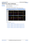
Figure 4-1. General overview of GVDC system architecture.
harvesting/federation system architecture, and 4) XML translators for producing
downloadable XML files from the various data provider’s databases mapped to the
geotechnical data dictionary developed by the DDWG (Chapter 3, Benoit et al., this
4-2
report). A detailed discussion on all of these applications can be found in Appendix 3 of
this report. A data storage strategy to permanently archive geotechnical data generated
through PEER Lifelines funding or by others is currently being designed and will be
implemented in the next phase of this project (COSMOS/PEER-LL 2L03).
4.2 FRONT END SYSTEM ARCHITECTURE
Technologically, the GVDC is essentially a GIS-based end user search interface coupled
with a back end database and harvester, and data translators (Figure 4-1). The GVDC
does not contain the actual boring logs, but rather maintains an index or metadata catalog
to available data from participating data providers in a MySQL database (MySQL, 2004),
consiting of descriptive information about the boreholes (e.g. date drilled, total depth,
types of test information available, etc.). The structure of the MySQL database conforms
precisely to the COSMOS/PEER-LL Geotechnical data dictionary and XML Schema
format (Chapter 3, Benoit et. al., and Appendices 2 and 3, this report). The GIS end user
interface was written in Microsoft Active Server Pages (ASP; W3C, 2004b) and utilizes
ESRI ArcIMS software for the map rendering service (Farallon, 2004). The GIS interface
is customized primarily in VBScript (W3C, 2004c) embedded in ASP web pages, while
the administrative (back end) Java Harvester fucntions are coded in Java Server Pages
(JSP; Sun, 2004) embedded in the overall ASP website design.
All end users connect to the GVDC system through browsers (Figure 4-2). The end user
is required to register and provide a user name and password (Figures 4-5). Once a user
has successfully logged into the website, the GIS map interface allows effective search of
the GVDC database by location or a specified region of interest (Figure 4-3). The user
may use the map tools (e.g. buttons for ZOOM, PAN, turn layers on and off) to navigate
and locate a general area of interest. The user may use the arrow selection tool to define
an area of interest on the map. Figure 4-6 shows an example area of interest delimited by
a box encompassing many boreholes in the Los Angeles area. The limits of the area are
automatically entered into the longitude and latitude boundaries form to the right of the
map. As an alternate method of defining a search area, the end user may enter coordinates
directly into the longitude and latitude boundaries form rather than drawing a box on the
map. Additional search criteria, including data types, dates of investigation, and total
borehole depth may be used to narrow the data selection (e.g. Figure 4-7: only boreholes
with SPT data that are between 1 and 10-m deep). Once the desired data are identified
and the user submits a search, a detailed list of borehole records follows with additional
information on each result, including the project name, the data type, the data source,
date, and any available downloads or contact information (Figure 4-8). The available data
are grouped in sets on the search results page, according to data provider. Check boxes
are provided to the right of each record on a search results page to allow the end user to
download geotechnical data in XML (ASCII) and/or Microsoft Excel formats. A
VBscript translator converts COSMOS/PEER-LL geotechnical XML schema-compliant
data on-the-fly into Excel (Softartisans, 2004). Each record represents a
COSMOS/PEER-LL geotechnical XML schema-compliant XML file, containing data on
a single type of test data from one borehole. Data exchange using the standardaized XML
4-3
Figure 4-2. GVDC user entry web page, https://geodata-cosmos-data.org.
files means that all data are downloadable in Excel and XML, irrespective of data source.
There may be many records in the list for each borehole, each containing a different type
of test data. Multiple files in one or both formats can be zipped simultaneousy on-the-fly
(ZBit, 2004). After a user has selected the desired records, the request is submitted by
clicking on the “Download Data From this Provider” button at the base of each set of
search results. The user must agree to the data usage policy, privacy policy and any
4-4
Figure 4-3. GVDC front end user GIS map interface.
disclaimer specified by the data provider, prior to downloading the data (Figure 4-9). If
the user agrees, the zip file containing the user’s selections is then streamed to the user
through a typical windows download dialog. The data zip file can then be can be saved
to a permanent media as desired by the end user.
Two data previewers are currently available that allow on-the-fly visualization of
geotechnical data through a GVDC search results page. A user can preview Cone
4-5
Figure 4-4. GVDC administrative web interface.
Penetration Tests (CPT) logs and borelogs dynamically. The previewers are activated by
clicking on “CPT” and “BLG” (Basic Lithology) under heading “Data Types” on a
search results page, respectively (i.e. Figure 4-10). The CPT previewer was created in
.NET by Caltrans, and displays CPT XML files on-the-fly using SVG (Scalable Vector
Graphics) (SVG; W3C, 2004; Grimes, 2004b). The borehole previewer was coded in
VB.NET and C/C++ by Savage Software (Savage, 2004). Borehole previews display
geologic and geotechnical information in a typical boring log format, for borehole
records containing sufficient detailed lithologic information (ROSRINE, 2001). Behind
the scenes (the back end), the data are retrieved using hyperlinks (URL’s) from the host
machine of the applicable agency.
If a borehole is shown on the map but the corresponding data is not yet available in the
COSMOS/PEER-LL standard format, contact information also stored in the GVDC
MySQL database is provided in the search results page.
4-6
Figure 4-5. Secure (SSL) GVDC system login page. This link takes the user to the map
interface and text-based documents search.
4.3 BACK END SYSTEM ARCHITECTURE
A comprehensive overview of the pilot project system architecture is provided in Figure
4-11. The details for the pilot project data providers’ (Caltrans, CGS, USGS and PG&E)
systems are illustrated on the right, and are discussed in detail in Appendix 3. Each data
provider maintains: 1) a native geotechnical data set or database including the searchable
parameters for the GVDC front end; 2) an OAIB installation which allows the GVDC to
harvest the search parameter data from the native database or data set; and 3) a data
translator for exporting data from it’s respective native format (such as Microsoft Access,
MySQL or PostgreSQL databases) into the standardized COSMOS/PEER-LL
geotechnical data XML format (Benoit et al., 2004).
Caltrans, CGS and PG&E maintain their searchable geotechnical parameters in Microsoft
Access databases, while the USGS utilizes PostgreSQL. Caltrans and USGS developed
new geotechnical databases based on the COSMOS/PEER-LL XML data format as part
of this project, while existing CGS and PG&E database structures were customized to
interact with the GVDC harvester. CGS is also currently implementing other custom
borehole download features through the CGS Seismic Hazards Mapping Program
website, a separate effort from this project (CGS, 2004). The GVDC CGS harvesting and
4-7
Figure 4-6. GVDC front end user GIS map interface, showing are selected using arrow
tool (upper left). A search of the GVDC MySQL database for the boreholes within the
search box will be invoked when the user clicks on the “Search” button (upper right).
data translation features were implemented using the same geotechnical database
structure currently integrated with the SHMP mapping website (CGS, 2004). Custom
Microsoft Visual Basic applications were written for the CGS and PG&E Access
databases, which directly translate the geotechnical data tables into XML files which are
automatically saved to the data providers’ servers. These XML translators also
automatically generate and store the URL’s to the XML files within these Access
databases. The URL’s are harvested concurrently with the other search parameters,
whenever the GVDC interacts with the OAIB installations. Caltrans wrote a .NET
translator that converts native CPT data files into COSMOS/PEER_LL geotechnical data
XML files (Grimes, 2004a). The USGS created a Java translator that dynamically
generates USGS XML files as XML, or initiates the GVDC Excel translator and
generates Excel spreadsheets containing the borehole record (Devlin, 2004). This
information is passed seamlessly as selected records are streamed to the user in a data zip
file. Thus the USGS data provider does not need to create and store XML files on their
server. The USGS Java translator is installed on the GVDC server.
4-8
Figure 4-7. GVDC front end user GIS map interface, showing use of Data Types Filter
(popup check boxes) and Total Borehole Depth Filter (lower right).
The Open Archives Initiative Protocol for Metadata Harvesting (OAI) was selected by
the project participants as an appropriate digital library protocol to implement the GVDC
harvester system (OAI, 2004). OAIB (NCSA, 2004a) was used to provide a set of OAI compliant data services backed by the providers’ databases, and a harvesting service used
by the GVDC to acquire data from those services. The OAIB installations on the data
providers’ servers include the following components: 1) Java Development Kit (JDK), 2)
Java, 3) Apache’s Jakarta Tomcat, 4) the OAIB Java files (NCSA, 2004), and 5)
configuration files mapping native data set attributes to their corresponding data names in
the MySQL database. The data provider’s servers and GVDC harvester components are
configured to allow access only to the GVDC server, and only to specific databases and
XML file directories. All four data providers will utilize firewalls to protect their OAIB
servers.
The system administrators include the GVDC developers and the data providers’
database administrators. The administrators are the super-users of the system. The GVDC
developer maintains the front end and back end web interfaces as well as an index of
available geotechnical borehole data from participating data providers in a MySQL
database. Administrators can activate the harvester and update the central database
whenever required (e.g. Figure 4-4). Whenever the update button is clicked, the GVDC
harvester interacts with the OAIB installations on the data providers’ servers. This
interaction takes the form of an update, which is either, and addition, update, or deletion
4-9
Figure 4-8. Search results page, listing records from the GVDC MySQL database
corresponding to the boreholes containing only SPT data, selected using the map
interface and arrow tool (Figure 4-7).
of data from the GVDC MySQL database. A confirmation is provided indicating either
success or failure for each update. If deleting records from the MySQL database, the
administrator must then click on the Delete option in order to delete records from the
GVDC that were earlier marked for deletion in the data providers’ database and uploaded
as such into the MySQL database. Thus each time an end user visits the GIS map
interface, the map is dynamically updated to display only the boeholes contained with the
GVDC MySQL database at that point in time.
The operation and maintenance costs for the GVDC system are minimal. The system uses
freeware and one yearly license for ESRI ArcIMS, and a one-time license for Softartisan
ExcelWriter. Upon completion, the labor cost for operation and maintenance of the
4-10
Figure 4-9. The CGS Data Usage and Privacy Policies. A user must agree to the data
provider’s data usage and privacy policies in order to download data.
4-11
Figure 4-10. A CPT Log is dynamically displayed in a new browser window by clicking
on the “CPT” link beneath “Data Types”.
Figure 4-11. Detailed overview of current GVDC system architecture.
4-12
existing system (four data providers) is estimated to be approximately 5 hours and 1 hour
per week, respectively. The time required to integrate new data providers to the GVDC
system, however, would require a full-time system developer.
4.4 SUMMARY OF GVDC SYSTEM
The development of the GVDC system is outlined the following steps:
" Basic administrative web interfaces were created using JSP forms.
" A GVDC MySQL database was created based on the COSMOS/PEER-LL
geotechnical data XML format, and connectivity from server-side scripts was
established.
" The data provider’s native geotechnical data sets were mapped to the
COSMOS/PEER-LL geotechnical data XML format, including complete borehole
test data attributes (Chapter 3, Benoit et al., this report).
" The OAIB components were installed on the data providers’ servers, and
configuration files were written to map the native data sets’ search parameters to
the COSMOS/PEER-LL geotechnical data XML format.
" The GVDC harvester code was written and implemented in Java. GVDC
administrators may add, update or delete beorhole recors through the GVDC
administrative website.
" The harvester code was connected to the OAIB services maintained on the data
providers’ servers.
" Tables for end user and administrator registration were created in the MySQL
database.
" The ability to change user login information is also provided; both end users and
administrators have the ability to save and change his/her profile. Administrators
also have an interface withint the administrator website for maintaining users
(subscribers) accounts.
" Data providers’ privacy policies were provided for the GVDC. These policies are
displayed on the end user data download pages, and are editable from within the
administrative user interface. A user must agree to these policies in order to
download data.
" Administrators may obtain resports on data download statistics through the
GVDC administrator website.
" The GIS end user interface was created in ASP (Farallon, 2004) using ESRI
ArcIMS and integrated into the existing overall website design, also written in
ASP.
" The ability to download data in Microsoft Excel was implemented using ASP and
Softartisan ExcelWriter.
" CPT and borelog previewers were written in VB.NET and and C/C++ and
integrated into the ASP search results web page.
The main advantages of the GVDC are as follows: 1) there is a central repository for
geotechnical search parameters from an unlimited number of data providers; 2) the
GVDC allows fast and efficient searching for borehole data; 3) the front end and back
end will both work even if one of the data providers is down; and 4) data providers’ data
4-13
sets may be updated as often as an administrator requires; ) sufficient accreditation and
individual privacy and use policies for each data provider have been integrated into the
front end interface; and 5) website security has been significantly enhanced. The
principal limitations of the GVDC include the following: 1) the GVDC has no way of
ensuring data consistency or quality; 2) data versioning and replication is dealt with
solely by the data provider, dependent on the date each record (borehole) was last
updated; 3) the end user has no way of knowing if data previously downloaded has been
updated; and 4) a tremendous amount of time and effort must be expended in order to
accurately map any one data provider’s data to the COSMOS/PEER-LL geotechnical
data XML format. Plans are currently being implemented to upgrade the front end web
interface to address limitations 4) within the next year.
4.5 2004 WORKSHOP
A workshop was held on June 21-23, 2004, to review the results of the project and
receive input from the geotechnical engineering community. The workshop included
presentations and discussions on the COSMOS-PEER Pilot System for Web
Dissemination of Geotechnical Data (this project) from a user as well as an
administrative perspective, and presentations, discussions and recommendations
regarding an Federal Highway Administration (FHWA) survey and assessment of
requirements for a web accessible distributed geotechnical data system for use by FHWA
and state DOTs. The workshop also included summary presentations of web enabled
geotechnical and environmental data dissemination systems currently deployed by the U.
S. Army Corp of Engineers and the British Geological Survey, and the plan for archiving
and web dissemination of geotechnical Instrumentation site data by the NEES
Consortium. Focused discussions identified issues related to implementation of a webenabled system for dissemination of distributed geotechnical data for general use.The
knowledge gained from this workshop will be applied in future upgrades of the GVDC
system architecture and databases. Proceedings of the workshop may be obtained by
contacting
COSMOS,
http://www.cosmos-eq.org,
or
PEER,
http://www.peer.berkeley.edu.
4.6 CONCLUSIONS
To make the Pilot GVDC a reality, institutional and technical hurdles were overcome. On
the institutional side, the participating organizations had a common interest in sharing
data and agreed on a framework for coordination (Swift et al., 2004). This included
finding acceptable mechanisms to assure data provider’s adequate control over their data
and a mechanism to provide appropriate attribution to the source of the data served by the
GVDC. On the technical side, the system architecture is now in place, an extensible
“standard” data dictionary and schema have been defined, standard file formats and
protocols have been utilized and further developed, CPT and borelog previewers have
been coded and implemented, database-to-XML and XML-to-Excel spreadsheet
translators have been written and implemented, and the websites are secured by SSL
encryption.
4-14
The GVDC front end website provides searching capabilities based on standard and welldefined geotechnical attributes. This caters to the current need of researchers and
engineers for an accessible, centralized geotechnical data source, and provides a framework for additional organizations to become data providers and share their data online.
Being a collaborative project of various organizations, this creates a platform for future
joint research, and reduces the need for repeated drilling and thus significantly reduces
costs for the organizations involved.
4.7 ACKNOWLEDGMENTS
A special thank-you to Joe Futrelle and Joel Plutchak at NCSA, for their continued
support of the OAIB architecture components. Singular acknowledgement goes to John
Bobbitt of POSC, for his extensive assistance in translating the new geotechnical data
dictionary into XML Schema. Special recognition goes to Dan Ponti and Sean Devlin at
USGS, Paul Grimes at Caltrans, Terilee McGuire at CGS, and Jianping Hu at USC for
their significant contributions to data set mapping and XML translator programming. The
authors would also like to thank the following participants in Task 3 of the project, who
provided valuable assistance in the GVDC development: Joseph Sun, Jean-Pierre Bardet,
Mindy Squibb, Hank Rastzesberger, Debra Bartling, Keith Farnsworth, Raghu
Satyanarayana, Scott Weaver, Bob Moscovitz, and Oscar Jarquin.
This project was conducted under the leadership of COSMOS and through funding under
Project 2L02 of PEER-LL; Carl Stepp was Principal Investigator and Jennifer Swift was
Co-principal Investigator. The PEER-LL Project is sponsored by Caltrans, the California
Energy Commission, and PG&E. This project was conducted in partnership with CGS
and the USGS.
4.8 REFERENCES
Benoît, J., Bobbitt, J., Ponti, D., and Shimel, S. (2004), “Data Dictionary and Formatting
Standard for Dissemination of Geotechnical Data”, submitted to Geo-Trans 2004, Los
Angeles CA, July 27-31.
Bobbitt, J., Benoit, J., Ponti, D., Turner, L., Shimel, S., Squibb, M., Corona, S., and
McGuire, T. (2004), “Cosmos Geotechnical XML Schema: Satellite Schema V1.0”,
Geotechnical
XML
Schema
work
website:
http://geoinfo.usc.edu/gvdc/geotech_schemas/Satellite.html (12/04).
CGS (2004), California Geological Survey, Seismic Hazards Mapping Website,
Interactive Mapping and GIS Data, http://gmw.consrv.ca.gov/shmp/index.htm.
Devlin, S., (2004), “Foqus XML Translation Software
COSMOS/PEER-LL 2L02 Internal Project Document, 2 p.
Documentation”,
Farallon (2004), Farallon Geographics Inc., http://www.fargeo.com (12/04).
4-15
Grimes, P. (2004a), “Converting data files to XML format – Caltrans CPT data
example”, COSMOS/PEER-LL 2L02 Internal Project Document, 11 p.
Grimes, P. (2004b), “CPT Pre-Viewer Application – Code Structure and Installation”,
COSMOS/PEER-LL 2L02 Internal Caltrans Report, 7 p.
MySQL (2004), MySQL, Open Source SQL database management system,
http://www.mysql.com/ (12/04).
NCSA (2004a), The Open Archives Initiative Protocol for Metadata Harvesting, Digital
Library Technology, National Center for Supercomputing Applications, UIUC,
Champaign, Il.,
http://www.openarchives.org/OAI/1.1/openarchivesprotocol.html (12/04).
NCSA (2004b), Open Archives in a Box (OAIB), Digital Library Technology,
National Center for Supercomputing Applications, UIUC, Champaign, Il.,
http://dlt.ncsa.uiuc.edu/oaib/ (12/04).
OAI (2004), Open Archives Initiative, http://www.openarchives.org/ (12/04).
Ponti, D. (2004), “USGS Electronic Borehole and Well Repository for the Los Angeles
Region”, Powerpoint Presentation to GeoTrans 2004, Los Angeles, CA, July 27-31,
2004.
PostgreSQL (2004), PostgreSQL, http://www.postgresql.org/ (12/04).
Savage (2004), Savage Software, http://www.savagesoftware.com/ (12/04).
Softartisans (2004), ExcelWriter, http://officewriter.softartisans.com/officewriter-37.aspx
(12/04).
Swift, J., Stepp, J.C., Vaughan, D., Grimes P., and Turner, L. (2002), “Collaborative
research on web dissemination of geotechnical data”, Conf. Report and Proc. National
Conference on Digital Government Research 2K02, National Science Foundation, Los
Angeles, CA, May 20-22, CD-ROM, 4 p.
Turner, L., Brown, M., Chambers, D., Davis, C., Diehl, J., Hitchcock, C., Holzer, T.,
Nigbor, R., Plumb, C., Real, C., Reimer, G., Steidl, J., Sun, J., TincptDataInfoey, J., and
Vaughn, D. (2004), “Baseline practices and user needs for web dissemination of
geotechnical data”, submitted to Geo-Trans 2004, Los Angeles CA, July 27-31.
W3C (2004a), Extensible Markup Language (XML), W3C World Wide Web
Consortium, http://www.w3.org/XML/ (12/04).
W3C (2004b), Introduction to ASP, W3C World
http://www.w3schools.com/asp/asp_intro.asp (12/04).
4-16
Wide Web Consortium,
ZBit (2004), ZBit zip-unzip component pro, http://www.zbitinc.com/product.aspx?p=1
(12/04).
4-17
APPENDIX 1
USER SURVEY RESULTS
Responses to the remaining survey questions are summarized in the following pages. In
general, bar charts and pie charts show the percentage of the total number of respondents
that indicated that particular response. Sub-categories of questions (indicated by XX.X.X
numbering notation) were presented to respondents only if they answered “Yes”,
“Absolutely Necessary”, or “Necessary” to the primary question. Percentages shown in
the charts reflect the responses only from those to which the questions were presented.
(16)
What types of geotechnical and related data do you routinely use in your
work? (Please check all that apply):
!
!
!
!
!
!
!
Geotechnical borehole data (soil classification, visual description,
groundwater level, etc.)
Geological borehole data (dating, bedding orientation, etc.)
Lab test data (e.g. consolidation, gradation, strength, etc.)
In-situ engineering test data (SPT, CPT, vane shear, pressure meter, etc.)
In-situ hydrogeologic test data (e.g. pumping tests, dye tests, fluid
penetration, etc.)
Geophysical test data (e.g. shear wave velocity, etc.)
Other
1-A1
The above chart shows the percentage of all of the respondents that checked
the particular response. Those that indicated “other” had responses including:
position, location, survey, vibration surveys (particle velocity and frequency),
secondary data sources, geotechnical reports, remote sensing data,
paleontology, lithologic outcrop data, earthquake catalogues, geologic maps,
geochemical sample information, foundation testing data, surface water and
weather climate data, faults, DEMS, earthquake epicenters, seismological, and
paleomagneto data.
2-A1
(17)
For what general purpose(s) do you use geotechnical data?
(Please check all that apply):
!
!
!
!
!
Environmental investigations
Site investigations to develop design recommendations and/or perform
geotechnical designs
Regional scale studies or hazard mapping
Calibration or validation of constitutive or predictive models
Other
The above chart shows the percentage of all of the respondents that checked
the particular response. Those that indicated “other” had responses including:
research studies, database development, risk evaluations, fossil identification,
geologic mapping, lithostratigraphy, aquifer characterization, construction
quality assurance, education, failure analysis, and forensic studies of failures.
3-A1
(18)
Do you develop maps or map related products?
!
!
Yes (63%)
No (37%)
(18.1) What kind(s) of techniques or software do you use for map making?
!
!
!
!
GIS
Hand drafting
CAD
Other
The above chart shows the percentage of all of the respondents that responded
“Yes” to the previous question. Those that indicated “other” had responses
including: GMT, Freehand, Illustrator, Canvas, contouring routines, and
gINT.
(18.2) Does your method of map making require geographic coordinates for borehole
locations?
!
!
Yes (82%)
No (18%)
4-A1
(19)
How does your organization typically acquire borehole data? (Please check all
that apply):
!
!
!
!
!
Conduct field drilling and logging operations with in-house staff
Contract to others for field drilling operations, but use in-house staff for
logging
Contract to others for field drilling and logging operations
Use existing, publicly available, data generated by others
Other
The above chart shows the percentage of all of the respondents that checked
the particular response. Those that indicated “other” had responses including:
private data sets, proprietary data sets, and consultant files.
5-A1
(20)
How important is it in your current work to have the project location
expressed in a geodetic system (latitude and longitude) or a coordinate system
(State Plane Northing and Easting) with appropriate datum and projection
reference information?
!
!
!
!
(21)
Absolutely necessary
Important
Neutral
Not important
How important is it in your work to have the project location expressed as a
street address?
!
!
!
!
Absolutely necessary
Important
Neutral
Not important
6-A1
(22)
How important is it in your work to have information on the reference
elevation of the drill site?
!
!
!
!
Absolutely necessary
Important
Neutral
Not important
(22.1) How important is it in your work to have information on how the reference
elevation was obtained? (e.g. estimated from topo map, surveyed by DGPS,
etc.):
!
!
!
!
Absolutely necessary
Important
Neutral
Not important
7-A1
(23)
How important is it in your work to have information on the total depth of the
borehole?
!
!
!
!
(24)
Absolutely necessary
Important
Neutral
Not important
How important is it in your work to have information on the purpose of the
borehole (e.g. geotechnical, environmental, monitoring well, etc.)?
!
!
!
!
Absolutely necessary
Important
Neutral
Not important
8-A1
(25)
How important is it in your work to have information on environmental or
situational conditions during the drilling operations (e.g. weather, temperature,
breakdowns, delays, etc.):
!
!
!
!
(26)
Absolutely necessary
Important
Neutral
Not important
How important is it in your work to have a description of the setting at the
location of the borehole (e.g. natural ground, fill, raised casing, etc.)?
!
!
!
!
Absolutely necessary
Important
Neutral
Not important
9-A1
(27)
How important is it in your work to have specific information about the
source of the data (e.g. organization, name of logger, name of driller, etc.)?
!
!
!
!
(28)
Absolutely necessary
Important
Neutral
Not important
How important is it in your work to have specific information on the drilling
equipment used to generate the borehole (e.g. manufacturer, model, etc.)?
!
!
!
!
Absolutely necessary
Important
Neutral
Not important
10-A1
(29)
How important is it in your work to have specific information on the drilling
tools (e.g. auger type and measurements, drill rod and casing type and
measurements, drill bits and sampler types, etc.)?
!
!
!
!
(30)
Absolutely necessary
Important
Neutral
Not important
How important is it in your work to have information as to drilling rate?
!
!
!
!
Absolutely necessary
Important
Neutral
Not important
11-A1
(31)
How important is it in your work to have information on soil color?
!
!
!
!
(32)
Absolutely necessary
Important
Neutral
Not important
How important is it in your work to have information on the age of the
deposits being drilled?
!
!
!
!
Absolutely necessary
Important
Neutral
Not important
12-A1
(32.1) What methods do you employ, or data do you use, to determine the age of the
deposits?
!
!
!
!
!
Radiocarbon or other absolute age samples
Pediologic profile descriptions
Paleontology information or faunal lists
Tephra correlations
Other
The above chart shows the distribution of methods or data used to determine
age of deposits. Those that indicated “other” had responses including: OSI,
TL, paleomag, lithologic correlation, stratigraphy, sample descriptions,
historic data, reference geologic maps, USGS, visual, relative lucustrine
relations, published reports, field relationships, prior regional geologic
mapping, and soil description and correlation across boreholes.
(33)
How important is it in your work to have information on the chemical
composition of the deposits or the pore fluids being drilled?
!
!
!
!
Absolutely necessary
Important
Neutral
Not important
13-A1
14-A1
(34)
What standard does your organization use to classify soils:
!
!
!
!
!
Visual-manual based USCS or extensions such as ASTM D2488
Lab-based USCS or extensions such as ASTM D2487
AASHTO
USDA Textural Chart
Other
The above chart shows the distribution of standards used to classify soils.
Those that indicated “other” had responses including: modified AASHTO,
Burmeister, BS5930, and specific versions of USCS modified for DOT use.
(35)
What types of field strength index test data do you utilize (not including insitu testing)?
!
!
!
!
None
Torvane
Pocket Penetrometer
Other
The above chart shows the distribution of types of strength index tests used in
the field. Those that indicated “other” had responses including: point load,
15-A1
unconfined compressive with spring loading, vane shear, finger, thumb, and
screwdriver.
16-A1
(35.1) How important to your work is it to have information on the make/model of
the particular test instrument and any key dimensions or tests parameters?
!
!
!
!
(36)
Absolutely necessary
Important
Neutral
Not important
How important is it in your work to have interpretations and comments (other
than lithologic descriptions) on a particular soil layer (e.g. fill, alluvium,
colluvium, etc.)?
!
!
!
!
Absolutely necessary
Important
Neutral
Not important
17-A1
(37)
How important is it in your work to have the information on the depth of
water in a borehole?
!
!
!
!
Absolutely necessary
Important
Neutral
Not important
(37.1) Do you require information on depth to water at various times in a boring in
addition to the final recorded water level?
!
!
Yes (52%)
No (48%)
(37.1.1) How important is it in your work to have information on the depth of first
water encountered in a borehole?
!
!
!
!
Absolutely necessary
Important
Neutral
Not important
18-A1
(37.1.2) How important is it in your work to have information on the interim water
level measurements in a borehole during the initial site investigation?
!
!
!
!
Absolutely necessary
Important
Neutral
Not important
(37.2) How important is it in your work to have information on the date and time of
water level measurement(s) in a borehole?
!
!
!
!
Absolutely necessary
Important
Neutral
Not important
19-A1
(37.3) How often is the borehole installed for purposes of long term monitoring
(months to years) of water level?
!
!
!
Frequent
Occasional
Seldom
(37.4) How important is it in your work to have information on packer tests, pump
tests, or other well development tests?
!
!
!
!
(38)
Absolutely necessary
Important
Neutral
Not important
Does your organization perform groundwater modeling?
!
!
Yes (38%)
No (62%)
20-A1
(38.1) What types of groundwater modeling software do you use?
!
!
!
!
!
None
MODFLO
MOC
Public Domain Software
Other
21-A1
(39)
What types of geotechnical lab test data do you use and/or generate? (Please
check all that apply):
!
!
!
!
!
!
!
!
!
!
!
!
!
!
!
Unit Weight
Moisture Content
Maximum/minimum Density, Relative Density
Specific Gravity
Particle Size Analysis
Atterberg Limits
Consolidation
Direct Shear Strength (friction angle and cohesion)
Unconfined Compressive Strength
Triaxial shear strength parameters (friction angle and cohesion)
Mohr-Coulomb envelope from triaxial tests
Full stress-strain curves from strength tests
R-value/CBR
Cyclic/Dynamic Properties
Other
The above chart shows the percentages of the respondents (that had indicated
that they used lab test data in question 16) that checked the particular
response. Those that indicated “other” had responses including: permeability,
relative compaction, corrosion, dispersion, miniature vane, sensitivity,
cyclic/static DSS, ASTM C-97, ASTM C-99, ASTM C-170, ASTM C-241,
ASTM C-880, LBR, erosion testing, loss on ignition, hydrometer, double
transverse shear, strain at 50% su, and soluble salts.
22-A1
(40)
How does your organization typically acquire lab test data? (Please check all
that apply):
!
!
!
!
Conduct lab testing internally
Contract to others for lab testing
Use existing, publicly available, data generated by others
Other
The above chart shows the percentages of the respondents (that had indicated
that they used lab test data in question 16) that checked the particular
response. Those that indicated “other” had responses including: use in-house
data banks, use data acquired by owner-hired geotechnical engineer,
requesting access to private data sets, use existing proprietary data, and
consultant files.
(41)
How important is it in your work to have the interpreted data (e.g.
Compression Index, Shear Strength, Unit Weight) readily available, as well as
information on the methods used to make the interpretations?
!
!
!
!
Absolutely necessary
Important
Neutral
Not important
23-A1
24-A1
(41.1) How important is it in your work to have the primary data (e.g. calibrated
settlement vs. time) readily available, as well as information on the factors and
methods used to develop the primary data (e.g. calibration constants, filtering
techniques, etc.)?
!
!
!
!
Absolutely necessary
Important
Neutral
Not important
(41.1.1) How important is it in your work to have the raw data readily available
(e.g. unprocessed transducer voltages)?
!
!
!
!
Absolutely necessary
Important
Neutral
Not important
25-A1
(41.1.1.1) How important is it in your work to have information on transducer
calibration data for test equipment?
!
!
!
!
Absolutely necessary
Important
Neutral
Not important
(41.2) How important is it in your work to have information on the lab test
equipment (e.g. make, model, type, key dimensions, transducers, etc.), test
conditions (e.g. estimated in-situ vertical pressure for a consolidation test), or
test specimen (e.g. initial sample thickness for a consolidation test) for a
particular test result?
!
!
!
!
Absolutely necessary
Important
Neutral
Not important
26-A1
(42)
What types of geotechnical in-situ test data do you use and/or generate?
(Please check all that apply):
!
!
!
!
!
!
!
!
!
Standard Penetration Test (SPT)
Cone Penetration Test (CPT)
Vane Shear Test (VST)
Pressuremeter Test (PMT)
Dilatometer Test (DMT)
Plate Load Test
Packer Test
Pump Test
Other
The above chart shows the percentages of the respondents (that had indicated
that they used in-situ test data in question 16) that checked the particular
response. Those that indicated “other” had responses including: blow counts,
resilient modulus, shelby tubes for direct shear, air hammer drives, stiffness
gauge, point load on rock, and electrical resistivity of soils.
27-A1
(43)
How does your organization typically acquire in-situ test data? (Please check
all that apply):
!
!
!
!
(44)
Conduct in-situ testing internally
Contract to others for in-situ testing
Use existing, publicly available, data generated by others
Other
How important is it in your work to have the interpreted data (e.g. CPT-based
soil type, undrained shear strength, pressuremeter modulus, corrected N1-60
SPT blow counts) readily available, as well as information on the methods
used to make the interpretations (e.g. assumptions of the water level elevation
or soil unit weight, etc.)?
!
!
!
!
Absolutely necessary
Important
Neutral
Not important
28-A1
(44.1) How important is it in your work to have the primary data (e.g. CPT tip
resistance and sleeve friction, depth, etc.) readily available, as well as
information on the factors and methods used to develop the primary data (e.g.
calibration constants, filtering techniques, etc.)?
!
!
!
!
Absolutely necessary
Important
Neutral
Not important
(44.1.1) How important is it in your work to have the raw data readily available
(e.g. unprocessed voltages from pressure and load transducers for CPT,
uncorrected blow counts for SPT)?
!
!
!
!
Absolutely necessary
Important
Neutral
Not important
29-A1
(44.1.1.1) How important is it in your work to have information on transducer
calibration data for test equipment (e.g. calibration for a pore pressure
transducer on a CPT cone)?
!
!
!
!
Absolutely necessary
Important
Neutral
Not important
(44.2) How important is it in your work to have information on the in-situ test
equipment (e.g. make, model, type, key dimensions, transducers, CPT cone tip
size, SPT hammer lifting mechanism, SPT hammer drop weight/length, SPT
energy transfer efficiency, etc.) and field test conditions (e.g. setup, layout,
etc.)?
!
!
!
!
Absolutely necessary
Important
Neutral
Not important
30-A1
(70)
What types of borehole geophysical test data do you use and/or generate?
(Please check all that apply):
!
!
!
!
!
!
!
!
!
!
!
!
!
!
!
Downhole P-wave velocity
Downhole S-wave velocity
Borehole acoustic televiewer
Optical Televiewer
Electric Resistivity (e.g. short normal and/or long normal)
Spontaneous Potential
Natural Gamma
Conductivity
Neutron Density
Gamma Density
Temperature
Radar
Full Waveform Sonic
Caliper
Other
The above chart shows the percentages of the respondents (that had indicated
that they used borehole geophysics data in question 16) that checked the
particular response. Those that indicated “other” had responses including:
tomography, crosshole S/P, seismic CPT, and heat pulse flow.
31-A1
(71)
Does your organization accept surface geophysical data to supplement
borehole geology, SPT, and sample tests, and if so what types do you use
(Please check all that apply)?
!
!
!
!
!
!
!
!
!
SASW Velocity Profile (shear wave velocity with depth)
Seismic Refraction (P-wave velocity with depth)
Seismic Reflection (either shear-wave or P-wave)
Resistivity (1D, 2D, or 3D)
2D or 3D radar
Gravity
Electromagnetics
Magnetics
Other
The above chart shows the percentages of the respondents (that had indicated
that they used borehole geophysics data in question 16) that checked the
particular response. Those that indicated “other” had responses including:
magnetotellurics, and ground penetrating radar.
32-A1
(72)
How does your organization typically acquire borehole geophysical test data
(Please check all that apply)?
!
!
!
!
(73)
Conduct borehole geophysical testing internally
Contract to others for borehole geophysical testing
Use existing, publicly available, data generated by others
Other
How important is it in your work to have the interpreted data (e.g. Poisson's
Ratio, shear modulus, shear wave velocity, etc.) readily available, as well as
information on the methods used to make the interpretations (e.g. wave arrival
picks, etc.)?
!
!
!
!
Absolutely necessary
Important
Neutral
Not important
33-A1
(73.1) How important is it in your work to have the primary data (e.g. calibrated and
filtered wave traces, etc.) readily available, as well as information on the
factors and methods used to develop the primary data (e.g. calibration
constants, filtering techniques, etc.)?
!
!
!
!
Absolutely necessary
Important
Neutral
Not important
(73.1.1) How important is it in your work to have the raw data readily available
(e.g. unprocessed transducer voltages)?
!
!
!
!
Absolutely necessary
Important
Neutral
Not important
34-A1
(73.1.1.1) How important is it in your work to have information on transducer
calibration data for test equipment?
!
!
!
!
Absolutely necessary
Important
Neutral
Not important
(73.2) How important is it in your work to have information on the test equipment
(e.g. make, model, type, key dimensions, transducers, etc.) and field test
conditions (e.g. setup, layout, etc.)?
!
!
!
!
Absolutely necessary
Important
Neutral
Not important
35-A1
(46)
What types of dynamic lab test data do you use or generate? (Please check all
that apply):
!
!
!
!
!
(47)
Shear modulus as a function of strain
Damping as a function of strain
Liquefaction behavior
Cyclic densification/settlement
Other
How does your organization typically acquire lab test data? (Please check all
that apply):
!
!
!
!
Conduct lab testing internally
Contract to others for lab testing
Use existing, publicly available, data generated by others
Other
36-A1
(48)
Which test methods are used to obtain these properties? (Please check all that
apply):
!
!
!
!
!
(49)
Cyclic triaxial
Cyclic simple shear
Resonant column torsional shear
Laboratory shear wave methods
Other
When using this data, how important is it for you to have access to the
interpreted data (e.g. number of cycles to liquefaction as a function of cyclic
stress ratio)?
!
!
!
!
Absolutely necessary
Important
Neutral
Not important
37-A1
(50)
When using this data, how important is it for you to have access to the
primary data (e.g. time histories of stress, strain, and pore pressures)?
!
!
!
!
(51)
Absolutely necessary
Important
Neutral
Not important
When using this data, how important is it to you to know the detailed test
conditions (e.g. locations and types of load and deformation transducers,
sequence of steps in procedures, measured B values, consolidation strains,
etc.) ?
!
!
!
!
Absolutely necessary
Important
Neutral
Not important
38-A1
(52)
In what form does your organization currently prepare, report, and/or archive
geotechnical data? (Please check all that apply):
!
!
!
!
(53)
Paper
Microfiche
Electronic
Other
What types of electronic formats do you use to store geotechnical data?
(Please check all that apply):
!
!
!
!
!
!
!
!
ASCII delimited text (e.g. text file with parameters separated by commas,
tab, etc.)
Rich Text Format (e.g. Word)
Database format (e.g. Access, Filemaker Pro, Oracle)
Spreadsheet format (e.g. Excel)
Image file (e.g. JPEG, TIFF)
Web-based Format (e.g. XML)
Proprietary binary format for specific software
Other
39-A1
Those that indicated “other” had responses including: GTGS, GIS, LogPlot,
ArcView, home made software, Microstation, Adobe PDF, gINT, Blog, DXF,
SDE, TIFF, Illustrator, and AGS.
40-A1
(54)
What computer software do you use to prepare geotechnical report products
(e.g. plots, charts, graphs, logs, etc.)? (Please check all that apply):
!
!
!
!
!
!
!
!
!
!
!
!
!
!
!
!
!
!
!
!
!
Excel
MathCad
Matlab
Mathmatica
Deltagraph
Rockworks
Logplot
GINT
Techbase
Applecore
Grapher
Surfer
GTGS
AutoCAD
Microstation
ArcView
MapInfo
Adobe Illustrator
FreeHand
Microsoft Word
Other
Those that indicated “other” had responses including: Acrobat, Winlog, Igor,
PSIPlot, Paintshop Pro, ArcINFO, Century Logging Display, WordPerfect,
CorelDraw, Photoshop, GMT, Geomedia, Access, LogDraft, Blog, proprietary
DOT systems, geosystem, stereonet, Kaleidegraph, Origin, Flash, Canvas,
41-A1
Borelog, Coneplot, Visio, Pagemaker, Integraph SGE, ERMA, MS Publisher,
SID, Keyhole, and Vulcan.
42-A1
(55)
What computer software do you use to process and analyze geotechnical data?
!
!
!
!
!
!
(56)
Excel
MathCad
Matlab
Mathmatica
Rockworks
Other
How important is it in your current work to have geotechnical data stored in
an electronic format?
!
!
!
!
Absolutely necessary
Important
Neutral
Not important
43-A1
(57)
How important do you think it will be for your future work to have
geotechnical data stored in an electronic format?
!
!
!
!
(58)
Absolutely necessary
Important
Neutral
Not important
How important is it in your current work to have geotechnical data initially
collected in an electronic format?
!
!
!
!
Absolutely necessary
Important
Neutral
Not important
44-A1
(58.1) How do you currently collect geotechnical data electronically?
!
!
!
!
!
Automated data acquisition with PC.
Automated data acquisition with PDA (e.g. Palm, PocketPC).
Manual data entry on a PC.
Manual data entry with PDA (e.g. Palm, PocketPC).
Other
Those that indicated “other” had responses including: GPS, and copy and
scan.
(59)
How important do think it will be for your future work to have geotechnical
data initially collected in an electronic format?
!
!
!
!
Absolutely necessary
Important
Neutral
Not important
45-A1
(59.1) How would you foresee collecting that geotechnical data? (Please check all
that apply):
!
!
!
!
!
Automated data acquisition with PC.
Automated data acquisition with PDA (e.g. Palm, PocketPC).
Manual data entry on a PC.
Manual data entry with PDA (e.g. Palm, PocketPC).
Other
Those that indicated “other” had responses including: data loggers, digital
recorder download to PC, not sure how many would be used, future software
on PC, unsure, and data transfer in AGS format.
(60)
Does your organization currently have a system in place that allows you to
access your own geotechnical data (not just bitmap images) in an electronic
format that is compatible with your current analysis and presentation tools?
!
!
Yes (37%)
No (63%)
Those that indicated “Yes” had responses including: ArcView, Access
database, PDF, NGES database, Filemaker Pro FOQUS, Intergraph, Sybase
Database, Project-by project Excel spreadsheets and GIS files, Excel, GISbased database format, spread sheet, gINT, ASCII, LabView, dynamic
websites, Foxpro, databases developed by our own staff, Oracle, ArcINFO,
plot drill holes and see locations on screen, internal network, Boring Log
Automation Program (developed in house), All test results (resilient modulus
soil testing), server access to gINT logs and Word, AutoCAD, MapInfo
Database, Microstation plots, MGE, Windows Notebook, 60spec, Access DB
through our GIS software (MGE), Intergraph, Geofinder, commercial
spreadsheet and graphing software, working on a intranet delivery system for
geologic data, Acad, Word, SID, and Techbase.
46-A1
(61)
If a new system was developed to allow you to access your own geotechnical
data in an electronic format compatible with your current analysis and
presentation tools, would you use such a tool?
!
!
(62)
Yes (78%)
No (22%)
If a new system was developed to allow you to access your own geotechnical
data, as well as data generated by other organizations/companies, in an
electronic format compatible with your current analysis and presentation tools,
would you use such a tool?
!
!
Yes (86%)
No (14%)
(62.1) Would your organization be interested in contributing data in some
standardized format to an information system used by others?
!
!
Yes (89%)
No (11%)
(62.2) In your opinion, how should such data be made available?
!
!
!
!
!
!
!
!
Freely available to all
Freely available to contributors of data
Annual fee for use to cover expenses
Per use fee to cover expenses
Annual fee for profit
Per use fee for profit
Freely available only to contributors of data
Other
47-A1
Those that indicated “Other” provided responses including: how would you
verify the quality of the contribute?, case by case basis, government supported
data should be free, different users have different customer bill, choice is
outside my responsibilities, a fee for noncontributors, reasonable fee to cover
expenses, at least free for students, undecided, not sure, our data could be
available to all, per use fee based on the amount of data, our data is public
information, available to licensed geotechnical engineers and geologists, data
owned by client not public, Charge non-contributors, big problems with this.
(63)
What type(s) of software and hardware tool(s) would you prefer to use to
access this data? (Please check all that apply):
!
!
!
!
!
Through the internet using a standard web browser (e.g. Netscape,
Explorer) on a personal computer.
Using a special program installed on your computer that accesses an
online data warehouse.
Through the internet using a web browser on a personal digital assistant
(e.g. Palm, PocketPC).
Using a special program installed on your personal digital assistant (e.g.
Palm, PocketPC) that accesses an online data warehouse.
Other
48-A1
Those that indicated “Other” provided responses including: web-based GIS,
tablet PC, and libraries still work well.
(64)
Please indicate how often you would use each of the following methods to
search for geotechnical data? (Frequent, Occasional, Seldom)
!
Location (e.g. map interface, Thomas Bros. Grid, Lat/Long, street address)
!
Data type (e.g. search only for data that contain SPT blow count
measurements, search only for monitoring well data, etc.)
!
Data value (e.g. search only for data with SPT blow counts less than 10,
search only for boreholes with specific lithologic descriptions, etc.)
49-A1
!
Quality of Data (e.g. search only for data that contain SPT blow counts
with measured transfer efficiency)
!
Source of Data (e.g. search only for data generated by USGS)
50-A1
!
Date of site investigation
!
Date that data was added to the information system.
!
Search by other parameter. Responses included: stratigraphic units,
person, and elevation of data point.
51-A1
(65)
How would you want the results of the search presented to you? (Please check
all that apply):
!
!
!
!
(66)
Do you need to have the capability to search/sort through your search results?
!
!
(67)
Graphical (e.g. points on a map)
Short text summaries of the data sets (e.g. key metadata)
Table of search results
Other
Yes (82%)
No (18%)
How would you prefer to preview the data resulting from the search? (Please
check all that apply):
!
!
!
Text preview of raw data (e.g. columns of numbers for CPT data)
Graphical preview of the data set (i.e. CPT data plotted with depth)
Other
52-A1
(68)
How would you prefer to download and use the geotechnical data? (Please
check all that apply):
!
!
!
(69)
Download immediately based upon the results of the short text summary,
text preview, graphical preview, or other form.
"Shopping Cart" method; check a box, continue searching, and download
everything later.
Other
In what format(s) would you prefer to download geotechnical data? (Please
check all that apply):
!
!
!
!
!
!
!
ASCII delimited text (e.g. text file with parameters separated by commas,
tab, etc.)
Rich Text Format (e.g. Word)
Database format (e.g. Access, Filemaker Pro, Oracle)
Spreadsheet format (e.g. Excel)
Image file (e.g. JPEG, TIFF)
Web-based Format (e.g. XML)
Other
53-A1
APPENDIX 2
DATA DICTIONARY TABLES AND SAMPLE MAPPING FROM SITE
TABLE TO XML
Alias
An alternate name for another object. The alternate name is defined
within a context, or naming system.
Name
Definition
Aliased Object
The foreign key reference to the object which is aliased.
Name
A name for this object. This name does not need to be unique within the
naming system.
Naming System
A list of names, or a method for developing a list of names, from which
Name is developed.
Atterberg Limits
The consistency of plastic soils defined in terms of shrinkage, plastic and
liquid limits.
Name
Specimen
Liquid Limit
Definition
The specimen, of which these Atterberg limits test results are a part. The
Atterberg limits test results must be related to a Specimen. This value is
a foreign key that should select an instance of Specimen based on the Id
value of the Specimen.
The water content of a soil at the arbitrary boundary between the semiliquid and plastic states, generally expressed in percent.
Liquid Limit Method
The name of the method used to determine the liquid limit. Methods
include the Liquid Limit Device and the Fall Cone.
Preparation Method
The name of the method used to prepare the specimen for the liquid limit
test. Methods include the Dry and Wet preparation.
Plastic Limit
Shrinkage Limit
Shrinkage Limit Method
Natural Water Content
Remarks
The water content of a soil at the arbitrary boundary between the plastic
and semi-solid states, generally expressed in percent.
The maximum water content at which a reduction in water content will
not cause a decrease in volume of the soil mass, generally expressed in
percent.
The name of the method used to determine the shrinkage limit. Methods
include the use of mercury or wax.
The water content of a soil in it's natural in situ moisture condition,
generally expressed in percent.
A text descriptor providing additional information relevant to the
Atterberg Limit test.
1-A2
Business Associate
Name
Name
The information about a business associate. The business associate may
be a person, company, group, agency, or any other person or collection
of persons that is related to the object.
Definition
A common name for this business associate. This name does not need to
be unique within the naming system.
Naming System
A list of names, or a method for developing a list of names, from which
Name is developed.
Type
The type of Business Associate. This should be one of the following:
{company, person, consultant, work group, agency, other}.
Street Address
The street portion of the address. This may be multiple lines.
City
The name of the city where the Business Associate address is located.
State
The name of the state where the Business Associate address is located.
Postal Code
The postal code, appropriate to the given country, where the Business
Associate address is located.
Country
Phone Number
Email
Associated With
Contact
The name of the country where the Business Associate Address is
located.
The phone number of the Business Associate. The phone number is
qualified by the type of phone number (eg, fax, voice, voice mail,
mobile) and the nature (business or personal).
The email address of a Business Associate.
The company or group that this Business Associate is associated with. If
the Business Associate is an employee, for example, the associate with
would be the company which employs her. This is a foreign key to
another instance of business associate. It is not required that the other
instance be instantiated.
A foreign key to another Business Associate who serves as a contact for
this Business Associate.
2-A2
Component
A physical feature or condition observed at a point or within an interval
of earth material within a hole, typically described megascopically. A
Component may represent a notable textural or lithologic feature within
a layer, or some other physical, structural, diagenetic, mineralogical,
biological, or geophysical characteristic. It also may represent a
condition (temporal or persistent) described at a point or within an
interval. A Component may exist within a Layer, or may extend across
many Layers.
Name
Definition
The hole, of which this Component is a part. A Component must be
related to a hole. This value is a foreign key that should select an
instance of Hole based on the Id value of the Hole.
The core, of which this component is a part. A component may or may
not be related to a Core. If used, this value should select an instance of
Core based on the Id value of the Core.
The layer, of which this Component is a part. A Component may or may
not be related to a layer. If a part of a Layer, this value should select an
instance of Layer based on the Id value of the Layer.
The data source or kind of sample used to describe the Component and
its location. This should be one of the following:{Core, CPT, Cuttings,
Geophysical Log, Estimate, Multiple Sources, Outcrop, Other}.
The measured depth at the top of the Component The depth is measured
from the depth datum of the hole, and is positive downward, as
measured along the hole alignment. The value may also be qualified by
who measured the depth {loggers, drillers}.
The measured depth to the base of the Component. The depth is
measured from the depth datum of the hole, and is positive downward,
as measured along the hole alignment. The value may also be qualified
by who measured the depth {loggers, drillers}
The name of the classification system used to describe the Component, if
applicable (e.g. Munsell color). This is expected to be a foreign key to an
instance, however there is no requirement that the instance exist.
The type of Component being described (e.g, color, roundness, sorting,
structural, physical, lithologic, diagenetic, mineralogic, fossil). This is
expected to be a foreign key to an instance, however there is no
requirement that the instance exist.
A name or description of the Component. This can be an element of a
classification system, and/or be restricted to a certain type of
Component, or be a general text descriptor.
A description of the relative pervasiveness of the Component within the
interval defined by the Component top and Component base. This is a
text descriptor and should provide some definition, such as: {pervasive
(>50%), abundant (30-50%), common (15-30%, few (5-15%), rare (15%),trace}.
Hole
Core
Layer
Source
Component Top
Component Base
Classification System
Type
Description
Abundance
3-A2
Core
An interval of earth materials, extracted or attempted to be extracted
from a hole or site, using a specific type of sampling device, and where
the physical locations of the ends of the Core are known in space. This
term is used to represent both the sample collected as well as the interval
within the hole that is sampled. If a physical sample of material is
recovered from the interval, it is contained within the interval and is
coherent, meaning that the material represents the relative position and
properties of the strata or geological material in its in-situ condition.
Material collected from a Core may be a) tested as a whole, b) further
sub-sampled for geotechnical lab tests, c) described in detail, or d)
subjected to geophysical tests, such as density scans, etc. Cores cannot
overlap within a single hole.
Name
Definition
Name
A common name for the Core. This name does not need to be unique
within the naming system.
Naming System
A list of names or a method for developing a list of names.
Hole
Core Top
Core Base
Sample Top
Sample Base
Sampling Method
The hole, of which this Core is a part. A Core must be related to a hole.
This value is a foreign key that should select an instance of Hole based
on the Id value of the Hole.
The measured depth to the top of the Core. The depth is measured from
the depth datum of the hole, and is positive downward, as measured
along the hole alignment. The value may also be qualified by who
measured the depth {loggers, drillers}.
The measured depth to the lowermost boundary of the Core. The depth is
measured from the depth datum of the hole, and is positive downward,
as measured along the hole alignment. The value may also be qualified
by who measured the depth {loggers, drillers}.
The inferred measured depth to the top of any sample recovered from the
Core. The depth is measured from the depth datum of the hole, and is
positive downward, as measured along the hole alignment. The value
may also be qualified by who measured the depth {loggers, drillers}.
The inferred measured depth to the base of any sample recovered from
the Core. The depth is measured from the depth datum of the hole, and is
positive downward, as measured along the hole alignment. The value
may also be qualified by who measured the depth {loggers, drillers}.
The name of the sampling method used to obtain a Core. Sampling
methods can be one of the following: a) undisturbed sampling by Shelby
tube or Piston sampler, b) disturbed sample by split-spoon, c) block
sample, d) disturbed sample by other methods, e) rotary drill cored
sample, or f) other sampling method.
Date
The date and time when the Core was sampled at the site.
Sample Length
The length of material recovered (solid or unconsolidated) from the
cored interval using one of the sampling methods.
Remarks
A text descriptor providing additional information relevant to the Core.
Examples of this could be drill rig behavior, driller's comments, and drill
time through the layer.
4-A2
Cone Penetration Test
Data
Name
Cone Penetration Test
Parameters
The cone penetration test (CPT) consists in determining the resistance to
penetration of a conical pointed penetrometer into subsurface soils.
Standard testing procedures are described in ASTM D 5778. Cone
Penetration data are presented in this table.
Definition
The Cone Penetration Test Parameters, of which these CPT data are a
part. The CPT data must be related to a Cone Penetration Test
Parameters. This value is a foreign key that should select an instance of
Cone Penetration Test Parameters based on the Id value of the Cone
Penetration Test Parameters.
Tip Depth
The depth of measurement at the penetrometer tip.
Tip Resistance
The end-bearing component of penetration resistance in units of stress
referred to as qc (uncorrected for net area ratio).
Friction Sleeve
Resistance
The friction component of penetration resistance in units of stress
developed on a friction sleeve refereed to as fs.
Penetration Pore
Pressure
Fluid pressure measured using the piezocone penetration test.
Inclination
Inclination of the penetrometer during advance in degrees.
Remarks
A text descriptor providing additional information relevant to the CPT
data and results.
Date Last Updated
The date of the last update to the data in this table.
Cone Penetration Test
Dissipation Data
During cone penetration testing it is possible to conduct dissipation tests
to evaluate the hydraulic conductivity of soils. The process consists in
stopping the penetrometer advance at the depth of interest and observing
the pore pressure decay with time. Standard testing procedures are
described in ASTM D 5778. Cone Penetration dissipation data are
presented in this table.
Name
Cone Penetration Test
Data
Definition
The Cone Penetration Test Data, of which these CPT dissipation data are
a part. The CPT dissipation data must be related to a Cone Penetration
Test Data. This value is a foreign key that should select an instance of
Cone Penetration Test Data based on the Id value of the Cone
Penetration Test Data.
Tip Depth
The depth of dissipation measurement at the penetrometer tip.
Penetration Pore
Pressure
Fluid pressure measured using the piezocone during the dissipation test.
Elapsed Time
Elapsed time of reading for dissipation measurement.
5-A2
Remarks
A text descriptor providing additional information relevant to the CPT
dissipation data, results and procedures.
Date Last Updated
The date of the last update to the data in this table.
Cone Penetration Test
Parameters
The cone penetration test (CPT) consists in determining the resistance to
penetration of a conical pointed penetrometer into subsurface soils.
Standard testing procedures are described in ASTM D 5778. Relevant
testing parameters are described in this table.
Name
Hole
Cone Type
Cone Manufacturer
Tip Area
Tip Apex Angle
Friction Sleeve Area
Distance Tip to Sleeve
Piezocone Type
Porous Element Type
Saturation Fluid
Saturation Method
Net Area Ratio
Correction
Push Rod Type
Friction Reducer
Definition
The hole, of which these CPT parameters are a part. The CPT
parameters must be related to a hole. This value is a foreign key that
should select an instance of Hole based on the Id value of the Hole.
The type of cone penetrometer used for testing. The following provides
a list of available cone penetrometers: a) mechanical cone, b) electric
cone, c) piezocone, d) seismic piezocone, e) lateral stress cone, f)
dynamic cone, g) acoustic cone, h) resistivity cone, i) vibratory cone, j)
miniature cone, or k) other.
The business name of the company manucturing the cone penetrometer.
For example, Fugro, Hogentogler, Delft, etc.
The conical base area of the penetrometer tip. Typical values are 10 cm2
and 15 cm2
The apex angle of the conical point of the penetrometer tip. The
standard value is 60 degrees.
The surface area of the friction sleeve located immediately behind the
penetrometer tip. Typical values are 150 cm2 for the 10 cm2 and 200
cm2 for the 15 cm2.
The distance between the tip and the center of the friction sleeve.
The type of Piezocone is defined in part by the position of the filter
element. The types in use are the following: a) Type 1 (on the tip apex
or at the midface on the tip), b) Type 2 (at the shoulder or behind the
tip), c) Type 3 (above the friction sleeve), or d) other.
The type of material used as porous filter element. The following
materials are typically used: a) plastic, b) sintered bronze, c) sintered
steel, d) ceramic, or e) other.
The fluid used to saturate the porous filter element. The following
deaired fluids are typically used: a) water, b) glycerin, c) silicon oil, or
d) other.
A description of the procedure used to saturate the porous filter element.
The correction necessary to adjust the penetration cone resistance due to
penetration water pressures acting behind the cone tip. The net area ratio
correction, a, is applied to the cone resistance qc which becomes the
corrected total cone resistance qt. The value a is dimensionless.
The type of pushing rods used for CPT penetration. Standard
nomenclature can be used such as A-rod or N-rod.
A description of the type, size and location of the friction reducer behind
the base of the cone should be reported if used.
6-A2
Penetration Rate
Tip Load Cell Capacity
Sleeve Load Cell
Capacity
Surface Load Cell
Capacity
Pore Pressure Load Cell
Capacity
Last Calibration Date
Remarks
Date Last Updated
The rate of advance of the penetrometer. Rate should be between 20 +/5 mm/second.
The capacity of the tip load cell.
The capacity of the sleeve load cell.
The capacity of the surface load cell.
The capacity of the pore pressure load cell.
The date of the last calibration of the penetrometer. Specify which
components were calibrated.
A text descriptor providing additional information relevant to the CPT
parameters and equipment especially if those differ from standard
requirements.
The date of the last update to the data in this table.
CRS
A coordinate reference system for which a set of coordinates is given.
This object contains information that will either reference a standard
CRS, or will define a local coordinate system particular to a site/ project.
Name
Definition
Name
A common name for the CRS. This name does not need to be unique
within the naming system.
Naming System
A list of names or a method for developing a list of names.
EPSG Code
The standard code for a well-known CRS, as defined and maintained by
the European Petroleum Survey Group (EPSG).
URL
The Uniform Resource Locator for a dictionary entry to the standard
CRS.
Type
Project Origin
Origin
North Direction
The type of CRS. Values are {geographic, projected, vertical,
engineering}.
A foreign key to the Project for which this CRS is a local, engineering
CRS. This value indicates that the Project has defined a Location
Reference Point, which is to be used as the origin for this CRS.
A description of a point which serves as the origin of the CRS. This is an
alternative to the Project Origin, which uses a Location Reference Point
as the origin.
The direction that is assumed to be north in the engineering CRS. This is
one of {true north, magnetic north, projected north, unknown}.
X Axis Azimuth
The rotation from the north direction of the X-axis. The rotation is
positive clockwise. If the x-axis is due east, the value would be 90 deg.
X Axis Description
A description of the X-axis. If the X Axis Azimuth is not given, then a
textual description of the direction of the X-axis should be given.
7-A2
Y Axis Rotation
The Y axis is assumed to be rotated 90 deg from the X axis. The rotation
may either be {clockwise, counter clockwise}. The usual value is
counter clockwise.
Hole
A single sampling station, from which earth materials are collected or
described, or earth material properties are measured. The sample may be
from a core or cuttings from a borehole, surface excavation, or any other
highly local sampling method. This term is used to represent the sample
collecting activity as well as the sampling station.
Name
Definition
Name
A common name for the hole. This name does not need to be unique
within the naming system.
Naming System
A list of names or a method for developing a list of names.
Site
Type
Driller
Logger
The Site of which this hole is a part. A hole must be related to a Site
This value is a foreign key that should select in instance of Site based on
the Id value of the Site.
The primary or current type of sampling station/hole. This is used to
supply more specificity to the Site Type. Value should be one of the
following: {see Hole Type sheet}.
The business associate that drilled the hole. This is intended to be a
foreign key to a possible database entry, although there is no expectation
that this entry will actually exist.
The business associate that logged the hole. This is intended to be a
foreign key to a possible database entry, although there is no expectation
that this entry will actually exist.
Start Date
The starting date of the collection activity for this hole.
End Date
The ending date of the collection activity for this hole.
Elevation
Elevation of the hole at the depth datum. Elevations are positive upward,
measured from the elevation datum.
Elevation Datum
The name of the elevation datum.
Map Projection
The map projection used to give the X and Y locations of the location
reference point.
Location X
Location Y
Local CRS
Geodetic Datum
The first coordinate for the location of the location reference point. In
the US, this would be the Easting.
The second coordinate for the location of the location reference point. In
the US, this would be the Northing.
A description of the local coordinate system which applies to local x,y
coordinates. This is expected to be a foreign key to an instance, however
there is no requirement that the instance exist.
The geographic coordinate system used to give the latitude and longitude
of the location reference point.
8-A2
Latitude
Longitude
Local X
Local Y
Depth Datum
Bottomhole depth
Inclination
Surface Geology
Location Method
Location Accuracy
Hole_Test_Assoc
Name
Hole
Hole Tests
Parent
Grandparent
The latitude of the location reference point, given in the Geodetic Datum
CRS.
The longitude of the location reference point, given in the Geodetic
Datum CRS.
The X location (first coordinate value) in the local CRS.
The Y location (second coordinate value) in the local CRS.
The datum from which depths are measured. If no value is given, it is
assumed that the datum is the ground level.
The measured depth of the hole at its deepest point. The depth is
measured from the depth datum, and is positive downward, as measured
along the hole alignment. The value may also be qualified by who
measured the depth {loggers, drillers}.
The variation from the vertical of the hole. The inclination must be a
positive value. If no inclination is given, the hole is interpreted to be
vertical, or a hole survey object (not yet defined) exists which describes
the path of the hole.
The surficial geologic unit at the location of this hole. This is intended to
be a foreign key to a possible database entry, although there is no
expectation that this entry will actually exist.
A description of the method by which the location reference point
coordinates were obtained. This should be one of the following: {DGPS,
Estimated from Well ID, GPS, Digitized from existing map, LORAN,
Posted to map from description, Unknown - from owner/operator,
Unknown - from 3rd party}.
An estimate of the accuracy of the location reference point. This should
be one of the following: {0.3 m (~1/100 sec), 3 m (~1/10 sec), 15 m
(~1/2 sec), 30 m (~1 sec), 90 m (~3 sec), <150 m (~5 sec), 300 m (~10
sec), 800 m (~1 min), >800 m (>~1 min)}.
The studies and analyses that are performed at a Hole and that may be
available for direct access through the Geotechnical Virtual Data Center.
Definition
The hole, of which this Hole Data is a part. Hole Data must be related to
a hole. This value is a foreign key that should select an instance of Hole
based on the Id value of the Hole.
The Hole Tests of which this Hole Data is a part. Test must be related to
a Hole Tests. This value is a foreign key that should select an instance of
Hole Tests based on the Id value of the Hole Tests.
The Parent Hole Tests of which this Hole Data is a part. Parent must be
related to a Hole Tests. This value should be the Parent attribute of the
Hole Tests associated with this instance of Hole Data.
The Grandparent Hole Tests of which this Hole Data is a part.
Grandparent must be related to a Hole Tests. This value should be the
Grandparent attribute of the Hole Tests associated with this instance of
Hole Data.
9-A2
Top Depth
Bottom Depth
XML File Name
Reference
Contact
The measured depth to the uppermost or shallowest extent of the Hole
Data. The depth is measured from the depth datum of the hole, and is
positive downward, as measured along the hole alignment. The value
may also be qualified by who measured the depth {loggers, drillers}.
The measured depth to the lowermost extent of the Hole Data. The depth
is measured from the depth datum of the hole, and is positive downward,
as measured along the hole alignment. The value may also be qualified
by who measured the depth {loggers, drillers}.
A URL of the XML file that contains the results of this hole data that
resides with the data provider. If this attribute is NULL, then the hole
data exists, but is not available for download from the data provider.
A reference to a publication or publications, and/or to a URL that reports
the hole data results, its implications, and the methods by which the data
were obtained.
The business associate to which inquiries about this Hole Data may be
addressed. This is intended to be a foreign key to a possible database
entry, although there is no expectation that this entry will actually exist.
Remarks
Hole Tests
The studies and analyses that are performed at a Hole and that may be
available for direct access through the Geotechnical Virtual Data Center.
Name
Definition
ID
A simple name for the Hole Test. This value is intended to be a primary
key for referencing this data instance.
Parent
A higher-level classification to which this Study Type belongs.
Grandparent
A higher-level classification to which the Parent belongs.
Description
A description of the Study Type.
Reference
A reference to a publication or publications, and/or to a URL that describe
the study or analysis and/or provides standard procedures for performing
the study or analysis.
InQuery
A flag that signifies whether the Geotechnical Virtual Data Center web
site will query on this field.
10-A2
Layer
Name
Hole
Core
Source
Layer Top
Layer Base
Classification System
Primary Classification
Secondary Classification
Tertiary Classification
Description
Remarks
Grain Size
An interval of earth material in which the texture and physical character
of the material are described. The layer is usually defined in terms of a
scientific or vernacular classification system. No layers in a given hole
defined within one classification system may overlap.
Definition
The hole, of which this layer is a part. A layer must be related to a hole.
This value is a foreign key that should select an instance of Hole based
on the Id value of the Hole.
The core, of which this layer is a part. A layer may or may not be related
to a core. If used, this value should select an instance of Core based on
the Id value of the Core.
The data source or kind of sample used to describe the layer and define
its boundaries. This should be one of the following:{Core, CPT, cuttings,
Geophysical Log, Estimate, Multiple Sources, Outcrop, Other}.
The measured depth to the top of the layer. The depth is measured from
the depth datum of the hole, and is positive downward, as measured
along the hole alignment. The value may also be qualified by who
measured the depth {loggers, drillers}.
The measured depth to the lowermost boundary of the layer. The depth
is measured from the depth datum of the hole, and is positive downward,
as measured along the hole alignment. The value may also be qualified
by who measured the depth {loggers, drillers}.
The name of the classification system used to describe the layer. This
can be a scientific system such as USCS, USDA, or AASHTO, or a
local, custom system. This is expected to be a foreign key to an instance,
however there is no requirement that the instance exist.
The value used as a primary description for the layer. This is intended to
be an element of the classification system.
The value used to describe a part of the layer considered to be a
secondary component of the layer. This is intended to be an element of
the classification system and is only relevant if the primary classification
attribute exists. The value may be qualified by the measured or estimated
percentage of the layer for which this classification is relevant.
The value used to describe a portion of the layer considered to be a
minor component of the layer. This is intended to be an element of the
classification system and is only relevant if the secondary classification
attribute exists. The value may be qualified by the measured or estimated
percentage of the layer for which this classification is relevant.
A text descriptor for the layer. This can be used to provide additional
descriptive information about the layer, or can be used In lieu of the
primary, secondary, or tertiary classifications.
A text descriptor providing information relevant to the layer interval, but
not specifically relevant to a description of the layer itself. Examples of
this could be drill rig behavior, driller's comments, and drill time through
the layer.
The average or representative grain size of the material in the layer. This
can be represented as a quantity of grain diameter (usually mm or phi),
or as a text descriptor. If a text descriptor, a definition or reference to a
classification system should be defined.
11-A2
Bedding
Basal Contact
Natural Moisture
Content
Name
Specimen
Natural Moisture
Content
Remarks
Particle Size Data
Name
Specimen
Particle Size Parameters
A description of the representative bedding thickness and character
within the layer, if observed. This is a text descriptor and should provide
a definition of the descriptor as: massive, thickly bedded (> dm),
medium bedded (cm-dm), thinly bedded (< cm), laminated}.
A description of the nature of the lowermost boundary of the layer, if
observed. This can be a text descriptor or member of a list as: {sharp,
broken, clear, diffuse, erosional, gradational, irregular, wavy, undulating,
inclined, angular unconformity, faulted, uncertain, incised}.
The in situ natural moisture or water content of geologic materials.
Definition
The specimen, of which this Natural Moisture Content is a part. The
Natural Moisture Content must be related to a Specimen. This value is a
foreign key that should select an instance of Specimen based on the Id
value of the Specimen.
The water content of a soil in it's natural in situ moisture condition. The
water content is the ratio of the mass of water contained in the pore
spaces of soil or rock material, to the solid mass of particles in that
material, generally expressed in percent.
A text descriptor providing additional information relevant to the
moisture content determination.
The distribution of particle sizes in soils as determined by sieve analysis
and/or hydrometer analysis.
Definition
The specimen, of which this Particle Size Data analysis is a part. The
Particle Size analysis must be related to a Specimen. This value is a
foreign key that should select an instance of Specimen based on the Id
value of the Specimen.
The Particle Size Parameters, of which these Particle Size Data are a
part. The Particle Size Data must be related to the Particle Size
Parameters. This value is a foreign key that should be an instance of
Particle Size Parameters based on the Id value of the Particle Size
Parameters.
Sieve or Particle Size
The sieve opening or the size of the soil particles.
Percent Passing
The percentage of soil passing or finer by weight or mass for each sieve
or size of soil particle.
Remarks
A text descriptor providing additional information relevant to the particle
size analysis of the soil specimen.
12-A2
Particle Size
Parameters
Name
Specimen
The distribution of particle sizes in soils as determined by sieve analysis
and/or hydrometer analysis. Relevant parameters and summary results
are presented in this table.
Definition
The specimen, of which this Particle Size analysis is a part. The Particle
Size analysis must be related to a Specimen. This value is a foreign key
that should select an instance of Specimen based on the Id value of the
Specimen.
D10
Grain diameter corresponding to 10 percent passing.
D50
Grain diameter corresponding to 50 percent passing.
Uniformity
Curvature
Percent Fines
A coefficient describing the degree of uniformity of the grain size
distribution. This coefficient is defined as the ratio of D60 over D10.
A coefficient describing the degree of curvature of the grain size
distribution. This coefficient is defined as the ratio of (D30)2 over (D60
times D10).
The percentage of fines by weight passing the No. 200 sieve (finer than
0.075 mm).
Remarks
A text descriptor providing additional information relevant to the particle
size analysis of the soil specimen.
Site
A collection of holes and samples obtained at a common place.
Name
Definition
A common name for the Site. This name does not need to be unique
within the naming system.
Name
Naming System
A list of names or a method for developing a list of names.
Type
Primary purpose for data collection at the Site. This should be one of the
following: {see Site Types sheet}
Address
The physical address for the site.
City
The name of the city where the site is located.
State
The name of the state where the site is located.
Zip
The zip (or postal code) where the site is located.
County
The name of the county where the site is located.
Country
The name of the country where the site is located.
13-A2
Quadrangle
PLSS
Organization
Contact
Location Reference
Point
Map Projection
Location X
Location Y
Geodetic Datum
Latitude
Longitude
Location Method
Location Accuracy
Data Source
The name of the USGS 7.5' quadrangle where the site is located.
The Public Land Survey System township, range, section, and quarterquarter section where the site is located.
The manager, operator or owner of the Site. This is intended to be a
foreign key to a possible database entry, although there is no expectation
that this entry will actually exist.
A name to contact for more information about the Site. This is intended
to be a foreign key to a possible database entry, although there is no
expectation that this entry will actually exist.
A description of a point at the Site which represents the location of the
Site. The location given in other attributes will be the location of this
point. In general, a local CRS (coordinate reference system) for locating
other objects at the site will use this as the origin.
The map projection used to give the X and Y locations of the location
reference point
The first coordinate for the location of the location reference point. In
the US, this would be the Easting.
The second coordinate for the location of the location reference point. In
the US, this would be the Northing.
The geographic coordinate reference system used to give the latitude and
longitude of the location reference point.
The latitude of the location reference point, given in the Geodetic Datum
CRS.
The longitude of the location reference point, given in the Geodetic
Datum CRS.
A description of the method by which the location reference point
coordinates were obtained. This should be one of the following: {DGPS,
Estimated from Well ID, GPS, Digitized from existing map, LORAN,
Posted to map from description, Unknown - from owner/operator,
Unknown - from 3rd party}.
An estimate of the accuracy of the location reference point. This should
be one of the following: {0.3 m (~1/100 sec), 3 m (~1/10 sec), 15 m
(~1/2 sec), 30 m (~1 sec), 90 m (~3 sec), <150 m (~5 sec), 300 m (~10
sec), 800 m (~1 min), >800 m (>~1 min)}.
The name of the original source of data obtained for this Site. This could
be the data provider itself, or another business associate that released the
information to the data provider. This is intended to be a foreign key to a
possible database entry, although there is no expectation that this entry
will actually exist.
14-A2
Specimen
A sample of earth material collected for the purpose of description or
testing. A specimen may be collected directly from a site or hole,
collected from the same Specimen material or from another Specimen.
Name
Definition
Name
A common name for the Specimen. This name does not need to be
unique within the naming system.
Naming System
A list of names or a method for developing a list of names.
Hole
Core
Layer
Part of Specimen
Specimen Top
Specimen Base
Sampling Method
Lithology Classification
System
Primary Lithology
Test
Collector
The hole, of which this Specimen is a part. A specimen must be related
to a hole, either through this attribute or through Core. This value should
select an instance of Hole based on the Id value of the Hole. Note: if
Specimen comes from a Core, then the Core attribute must be populated
and a value for Hole is not required.
The Core, of which this Specimen is a part. A Specimen may or may not
be related to a Core. If used, this value should select an instance of Core
based on the Id value of the Core.
The layer, of which this Specimen is a part. A Specimen may or may not
be related to a Layer. If a part of a Layer, this value should select an
instance of Layer based on the Id value of the Layer.
The Specimen of which this Specimen is a part. If this Specimen is a
split of a previously collected Speciment or resampled for a different
test, this attribute should be populated. If used, this value should select
an instance of Specimen based on the Id value of the Specimen.
The measured depth to the top of the Specimen. The depth is measured
from the depth datum of the hole, and is positive downward, as
measured along the hole alignment. The value may also be qualified by
who measured the depth {loggers, drillers, lab technicians}.
The measured depth to the lowermost boundary of the Specimen. The
depth is measured from the depth datum of the hole, and is positive
downward, as measured along the hole alignment. The value may also be
qualified by who measured the depth {loggers, drillers, lab technicians}.
The name of the sampling method used to obtain a Specimen. Sampling
methods should be one of the following: {Block sample, Bulk sample,
Core plug, Other, Split-core section, Whole-core section}.
The name of the classification system used to describe the lithology of
the Sample. This can be a scientific system such as USCS, USDA, or
AASHTO, or a local, custom system. This is expected to be a foreign
key to an instance, however there is no requirement that the instance
exist.
The value that describes the primary lithology of the Specimen. This is
intended to be an element of the classification system.
The name of the test for which the Specimen was collected. This is
intended to be a name from an enumerated list, and should be one of
those listed on the Tests worksheet.
The business associate that collected the Specimen. This is intended to
be a foreign key to a possible database entry, although there is no
expectation that this entry will actually exist.
15-A2
Date
The date and time when the Specimen was obtained from the cored
interval or other specimens.
Remarks
A text descriptor providing additional information relevant to the
Specimen.
Standard Penetration
Test Data
The standard penetration test (SPT) involves driving a split-spoon
sample barrel into the ground from the bottom of a borehole by dropping
a 140 lb (63.5 kg) hammer a height of 30 inches (0.76 m). From the test,
a penetration resistance or blowcount (N) is obtained which equals the
number of blows to drive the sampler over the depth interval between 6
and 18 inches (150 to 450 mm). The N-value is reported in blows per
foot (blows per 300 mm). Standard testing procedures are described in
ASTM D 1586. SPT results are presented in this table.
Name
Hole
Core
SPT Parameters
Blows First
Blows First Penetration
Blows Second
Blows Second
Penetration
Blows Third
Blows Third Penetration
Definition
The hole, of which these SPT data are a part. The SPT data must be
related to a hole. This value is a foreign key that should select an
instance of Hole based on the Id value of the Hole.
The core, of which these SPT are a part. The SPT data must be related
to a Core. This value is a foreign key that should select an instance of
Core based on the Id value of the Core.
The SPT Parameters, of which these SPT data are a part. The SPT data
must be related to the SPT Parameters. This value is a foreign key that
should select an instance of SPT Parameters based on the Id value of the
SPT Parameters.
The number of blows required to drive the split-spoon sampler for the
first 6 inch (150 mm) increment. This first increment is considered the
seating drive. Penetration is stopped and often noted as "refusal" if the
number of blows reaches 50 for any of the 6 inch (150 mm) increment or
if there is no observed advance during the application of 10 successive
blows or if the total number of blows have reached 100.
Penetration for first increment. Complete increment is 6 inch (150 mm).
Partial increment should be recorded to the nearest inch (25 mm).
The number of blows required to drive the split-spoon sampler for the
second 6 inch (150 mm) increment. Penetration is stopped and often
noted as "refusal" if the number of blows reaches 50 for any of the 6
inch (150 mm) increment or if there is no observed advance during the
application of 10 successive blows or if the total number of blows have
reached 100.
Penetration for second increment. Complete increment is 6 inch (150
mm). Partial increment should be recorded to the nearest inch (25 mm).
The number of blows required to drive the split-spoon sampler for the
third 6 inch (150 mm) increment. Penetration is stopped and often noted
as "refusal" if the number of blows reaches 50 for any of the 6 inch (150
mm) increment or if there is no observed advance during the application
of 10 successive blows or if the total number of blows have reached 100.
Penetration for third increment. Complete increment is 6 inch (150
mm). Partial increment should be recorded to the nearest inch (25 mm).
16-A2
Blows Fourth
Blows Fourth
Penetration
N Value
N Value Top Depth
The number of blows required to drive the split-spoon sampler for the
fourth 6 inch (150 mm) increment if a 24 inch (600 mm) sampler is used.
Penetration is stopped and often noted as "refusal" if the number of
blows reaches 50 for any of the 6 inch (150 mm) increment or if there is
no observed advance during the application of 10 successive blows or if
the total number of blows have reached 100.
Penetration for fourth increment. Complete increment is 6 inch (150
mm). Partial increment should be recorded to the nearest inch (25 mm).
The uncorrected SPT N-Value is defined as the sum of second and third
increments (from 6 to 18 inches - 150 to 450 mm). Deviation from this
definition occurs if penetration is stopped due to any of the 6 inch (150
mm) increment reaching 50 blows or if there is no observed advance
during the application of 10 successive blows or the total number of
blows have reached 100. Such deviations should be reported as number
of blows for each complete 6 inch increment or number of blows for
each partial increment. Partial increments should be reported to the
nearest inch (25 mm).
The measured depth associated with the beginning of the interval of
penetration for the reported N Value.
N Value Base Depth
The measured depth associated with the end of the interval of
penetration for the reported N Value.
Measured Energy
The measured energy ratio expressed as a percentage.
Remarks
A text descriptor providing additional information relevant to the
Standard Penetration Test of the soil specimen.
Date Last Updated
The date of the last update to the data in this table.
Standard Penetration
Test Parameters
The standard penetration test (SPT) involves driving a split-spoon
sample barrel into the ground from the bottom of a borehole by dropping
a 140 lb (63.5 kg) hammer a height of 30 inches (0.76 m). From the test,
a penetration resistance or blowcount (N) is obtained which equals the
number of blows to drive the sampler over the depth interval between 6
and 18 inches (150 to 450 mm). The N-value is reported in blows per
foot (blows per 300 mm). Standard testing procedures are described in
ASTM D 1586. Relevant testing parameters are described in this table.
Name
Sampler Length
Definition
The length of the split-spoon sampler barrel. Standard lengths are 18
inches (450 mm) and 24 inches (600 mm).
Sampler Internal
Diameter
The inside diameter of the split-spoon sampler.
Liner
The use of a liner to produce a constant inside diameter is permitted and
should be noted.
Basket
The use of a basket retainer is permitted and should be noted.
17-A2
Hammer Mass
Hammer type
Hammer Release
Drop Height
The hammer mass used to drive the split-spoon sampler. The standard
mass is 140 lb (63.5 kg).
The type of hammer or drive-weight assembly used for the sampling and
penetration. Typical hammer types include the following: a) donut, b)
safety, or c) other.
The mechanism used to lift and drop the hammer or drive-weight
assembly. Typical hammer release mechanisms include the following:
a) rope and cathead, b) trip, c) semi-automatic, d) automatic, or e) other.
The hammer drop height for SPT penetration. The standard procedure
requires a drop of 30 inches (0.76 m).
Rod Type
The type of sampling rods used for SPT penetration. Standard
nomenclature can be used such as A-rod or N-rod.
Rod External Diameter
The external diameter of the sampling rods used for SPT penetration.
Rod Weight
The drive rod weight per unit length (typically given per meter or per
foot).
Cathead diameter
The diameter of the cathead used to pull the rope attached to the
hammer. Typical diameters range from 6 to 10 inches (150 to 250 mm).
Rope Turns Number
The number of rope turns on the cathead for performing the SPT.
Maximum allowed number of turns is 2 1/4.
Energy
Remarks
Date Last Updated
A description of the equipment used to measure energy during the SPT
penetration.
A text descriptor providing additional information relevant to the SPT
parameters and equipment especially if those differ from standard
requirements.
The date of the last update to the data in this table.
18-A2
Sample Mapping: Site Table to XML
An example mapping is shown that takes the information from the Site table, and encodes it
into XML schema, and is expressed in an XML file.
The schema is shown below:
<xsd:element name="Site" type="siteTableType">
<xsd:annotation>
<xsd:documentation>
The Site is a collection of holes and samples obtained at a common place.
It is a direct parent of Hole, and offers the top level of the context
hierarchy.
</xsd:documentation>
</xsd:annotation>
</xsd:element>
<xsd:complexType name="siteTableType">
<xsd:annotation>
<xsd:documentation>
The Site is a collection of holes and samples obtained at a common place.
It is a direct parent of Hole, and offers the top level of the context
hierarchy.
</xsd:documentation>
</xsd:annotation>
<xsd:sequence>
<xsd:element name="ID" type="codeSysElAttType">
<xsd:annotation>
<xsd:documentation>
A code or simple name for a Site. This value is intended to be a foreign
key for referencing this data instance.
</xsd:documentation>
</xsd:annotation>
</xsd:element>
<xsd:element name="Name" type="nameSysElAttType" minOccurs="0">
<xsd:annotation>
<xsd:documentation>
A common name for the Site. This name does not need to be unique within
the naming system.
</xsd:documentation>
</xsd:annotation>
</xsd:element>
<xsd:element name="Alias" type="nameSysElAttType" minOccurs="0"
maxOccurs="unbounded">
<xsd:annotation>
<xsd:documentation>
Zero or more alternate names for the Site. This name does not need to be
unique within the naming system. This element is useful if the Site has
different names in different databases, or if it is known in the industry
by different names.
</xsd:documentation>
19-A2
</xsd:annotation>
</xsd:element>
<xsd:element name="Type" type="extSiteTypeEnum" minOccurs="0">
<xsd:annotation>
<xsd:documentation>
Primary purpose for data collection at the Site. These values are from an
enumerated list, and may be extended using Other: xx method.
</xsd:documentation>
</xsd:annotation>
</xsd:element>
<xsd:element name="Organization" type="simpleRefType" minOccurs="0">
<xsd:annotation>
<xsd:documentation>
A reference to a business associate that is the owner at the Site.
Details about the business associate may, if desired, be carried in the
dictionary portion or this exchange file, or may obtainable through a
service.
</xsd:documentation>
</xsd:annotation>
</xsd:element>
<xsd:element name="Contact" type="simpleRefType" minOccurs="0">
<xsd:annotation>
<xsd:documentation>
A reference to a business associate that is the contact at the site, at
the time of data collection. There is no expectation that the site
contact will be the same at a later date.
</xsd:documentation>
</xsd:annotation>
</xsd:element>
<xsd:element name="SiteAddressLocation" minOccurs="0">
<xsd:annotation>
<xsd:documentation>
The geopolitical location (state, city, county, country) of the Site,
with the address added to the sequence of values. In geotechnical
sampling, a site can often be located with a simple address.
</xsd:documentation>
</xsd:annotation>
<xsd:complexType>
<xsd:sequence>
<xsd:element name="Address" type="xsd:string" minOccurs="0"
maxOccurs="unbounded">
<xsd:annotation>
<xsd:documentation>
The physical address for the site. The site may be located by giving an
address.
</xsd:documentation>
</xsd:annotation>
</xsd:element>
<xsd:element name="City" type="xsd:string" minOccurs="0">
<xsd:annotation>
<xsd:documentation>
The name of the city where the site is located.
</xsd:documentation>
</xsd:annotation>
</xsd:element>
20-A2
<xsd:element name="State" type="stateCodeEnum" minOccurs="0">
<xsd:annotation>
<xsd:documentation>
The name of the state where the site is located. The state is given as
the two character postal code.
</xsd:documentation>
</xsd:annotation>
</xsd:element>
<xsd:element name="County" type="xsd:string" minOccurs="0">
<xsd:annotation>
<xsd:documentation>
The name of the county where the site is located.
</xsd:documentation>
</xsd:annotation>
</xsd:element>
<xsd:element name="Country" type="countryCodeEnum" minOccurs="0">
<xsd:annotation>
<xsd:documentation>
The name of the country where the site is located. Either the two or
three character ISO code may be used. For the United States, the
appropriate codes would be US or USA.
</xsd:documentation>
</xsd:annotation>
</xsd:element>
</xsd:sequence>
</xsd:complexType>
A sample of an XML file instantiated from the above schema is shown below:
<Site>
<ID codeSpace="USGS_ID">Lonr C_31861788_bD19</ID>
<Name namingSystem="USGS_PostgreSQL_name">15</Name>
<Name namingSystem="USGS_common_name">Long Beach - Pier C</Name>
<Alias namingSystem="USGS_Abbreviation">LBPC</Alias>
<Alias namingSystem="USGS_Other_ID">Long Beach-4</Alias>
<Type>geotechnical</Type>
<Organization>CalWaterRep</Organization>
<Contact>Dan Ponti</Contact>
<SiteAddressLocation>
<Address>Street address if known</Address>
<City>Long Beach</City>
<State>CA</State>
<County>Los Angeles</County>
<Country>US</Country>
</SiteAddressLocation>
<LocationReferencePoint>Western end of Pier C Container facility,
adjacent to Channel Two</LocationReferencePoint>
<Quadrangle>LONG BEACH</Quadrangle>
<PLSS xsi:type="USLegal">
<Township>5S</Township>
<Range>13W</Range>
<Section>3</Section>
<PrincipalMeridian>San Bernardino Base and
Meridian</PrincipalMeridian>
</PLSS>
21-A2
<Location>
<CRS>NAD83</CRS>
<LatitudeValue uom="deg">33.77095</LatitudeValue>
<LongitudeValue uom="deg">-118.22052</LongitudeValue>
</Location>
<!-- Can also include a non-lat/lon location, if desired.
<Location>
<CRS>UTM 11N / NAD83</CRS>
<Easting uom="m">386982.7</Easting>
<Northing uom="m">3737429</Northing>
</Location>
-->
<LocationMethod>GPS</LocationMethod>
<LocationAccuracy>3 m</LocationAccuracy>
<DataSource>USGS</DataSource>
<LastUpdated>2002-08-29</LastUpdated>
<Hole>. . .
information about Holes, Cores, Specimen, etc are also included.
</Site>
22-A2
APPENDIX 3
COSMOS/PEER-LL XML SCHEMA, DETAILED SYSTEM
ARCHITECHTURE DESCRIPTION, AND WORKFLOWS
Jennifer Swift1, Joe Futrelle2, Dan Ponti3, John Bobbitt4, Charles Real5, Paul Grimes6,
Sean Devlin3, Alexei Peters7, Joesph Castro8, Ivan Ninic9, Shahzad Tiwana10, Jianping
Hu1, Loren Turner6 and Carl Stepp11
1
Department Civil and Environmental Engineering, KAP 230A, University of Southern
California, Los Angeles, CA 90089; Email: [email protected]
2
The National Center for Supercomputing Applications (NCSA), 152 Computing
Applications Building, 605 E. Springfield Ave, Champaign, IL 61820, Email:
[email protected]
3
United States Geological Survey (USGS), Menlo Park, CA; Email: [email protected],
[email protected]
4
Petrotechnical Open Software Consortium (POSC), P.O. Box 270505, Houston, TX
77277; Email: [email protected]
5
California Geological Survey, 801 K. Street MS 12-31, Sacramento, CA 95914; Email:
[email protected]
6
Geotechnology Implementation Branch Division of Research & Innovation, California
Department of Transportation, 5900 Folsom Blvd.MS-5, Sacramento, CA 95819; Email:
[email protected]
7
Farallon Geographics, Inc., 609 Mission St. 2nd Floor, San Francisco, CA 94105;
Email: [email protected]
8
Internovations, 7071 Warner Ave., #F-372, Huntington Beach, CA 92647; Email:
[email protected]
9
Savage Software, #310 - 3495 Cambie Street, Vancouver, BC, V5Z 4R3; Email:
[email protected]
10
Computer Sciences, University of Southern California, Los Angeles, CA 90089; Email:
[email protected]
11
Consortium of Strong Motion Observation Systems (COSMOS)
Building 454, Room 121, 1301 South 46th Street, Richmond, CA 94804-4698; Email:
[email protected]
1
TABLE OF CONTENTS
1.0 INTRODUCTION ........................................................................................................ 5
2.0 COSMOS/PEER-LL GEOTECHNICAL XML SCHEMA.......................................... 5
2.1 Schema Document Properties ................................................................................... 8
2.1.1 Declared Namespaces ........................................................................................ 8
2.2 Global Schema Components..................................................................................... 8
2.2.1 Element: GeotechnicalData ............................................................................... 8
2.2.2 Element: _Dictionaries....................................................................................... 9
2.2.3 Element: Site.................................................................................................... 10
2.2.4 Element: _Tests................................................................................................ 13
2.2.5 Element: Tests.................................................................................................. 13
2.2.6 Element: SupportingData................................................................................. 15
3.0 GVDC DATABASE STRUCTURE........................................................................... 46
4.0 CLIENT SIDE DATA PREPARATION AND EXCHANGE PROTOCOL ............. 51
4.1 Data Mapping, Static XML Translation, and OAIB Customization ...................... 54
4.1.1 California Geological Survey (CGS) ............................................................... 54
4.1.2 California Department of Transportation (Caltrans)........................................ 63
4.1.3 United States Geological Survey (USGS) ....................................................... 79
4.1.4 Pacific Gas & Electric...................................................................................... 82
4.2 OAIB – Open Archives in a Box ............................................................................ 83
4.3 OAI – Open Archives Initiative.............................................................................. 84
5.0 SERVER SIDE BACK END SYSTEM ARCHITECTURE...................................... 85
5.1 Dynamic XML Translation..................................................................................... 85
6.0 FRONT END WEBSITE............................................................................................ 86
6.1 Main Website Design.............................................................................................. 86
6.2 GIS Map Application Code Structure..................................................................... 89
6.2.1 Gateway/Flow control blocks .......................................................................... 89
6.2.2 Function/Processing Blocks............................................................................. 89
6.2.3 HTML Blocks .................................................................................................. 90
6.2.4 Global Variables .............................................................................................. 90
6.3 Data Previewers ...................................................................................................... 91
6.3.1 SVG Previewer for Boreholes ......................................................................... 92
6.3.2 VB.NET SVG Previewer for CPT Logs .......................................................... 93
6.4 GVDC Server Side Code Structure......................................................................... 97
6.5 Search Results – Data Download............................................................................ 97
6.5.1 Download in XML.......................................................................................... 99
6.5.2 Download in Excel......................................................................................... 100
7.0 WORKFLOWS......................................................................................................... 100
7.1 Installation of ESRI ArcIMS ................................................................................ 100
7.2 Update COSMOS/PEER-LL Geotechnical XML Schema and GVDC................ 111
Task 1 - Modify the server-side and client-side COSMOS/PEER-LL Pilot GVDC
system architecture, and upgrade the system server to support a larger user-base. 112
Task 2 – Expansion of the Data Dictionary Standard............................................. 113
Task 3 – Development of an Operation and Maintenance Plan.............................. 114
8.0 DATA USAGE AND PRIVACY POLICIES .......................................................... 114
2
8.1 GVDC Data Usage and Privacy Policies .............................................................. 114
8.1.1 Use Policy ...................................................................................................... 114
8.1.2 Privacy Policy ................................................................................................ 117
8.2 Individual Data Provider Policies ......................................................................... 117
8.2.1 California Geological Survey ........................................................................ 118
8.2.2 California Department of Transportation (Caltrans)...................................... 125
8.2.3 United States Geological Survey (USGS) ..................................................... 125
8.2.4 Pacific Gas & Electric (PG&E) ..................................................................... 125
9.0 REFERENCES ......................................................................................................... 125
10.0 CONTACT INFORMATION................................................................................. 128
LIST OF FIGURES
Figure 1. Geotechnical Data Dictionary entity relationship Entity Relationship (ER)
Diagram (Benoit et al., this report). .................................................................................... 6
Figure 2. Example Access database constructed for testing the proposed geotechnical
database model, equivalent to the data dictionary (Benoit et al., this report)................... 49
Figure 3. Relationship diagram of geotechnical and reference relational data structures
(MS Access)...................................................................................................................... 50
Figure 4. The “gvdc” MySQL relational database, viewed using MySQL Control Center.
........................................................................................................................................... 51
Figure 5. General schematic of the “Data Mapping” process........................................... 52
Figure 6. Relationship diagram of native CGS database tables and keys (MS Access). See
Table 2 for more information on tables. ........................................................................... 54
Figure 7. Schematic overview of CGS remote database and GVDC system architecture.
........................................................................................................................................... 55
Figure 8. Relationship diagram of customized CGS database tables and keys (MS
Access).............................................................................................................................. 60
Figure 9. Schematic view of how the CGS database customized to interoperate with the
GVDC can be integrated with the SHMP website............................................................ 61
Figure 10. CPT data file archive at Caltrans..................................................................... 64
Figure 11. Relationship diagram of Caltrans database tables and keys (MS Access). See
Tables 5, 6 and 7 for more information on tables. ............................................................ 66
Figure 12. Schematic overview of Caltrans remote database and GVDC system
architecture........................................................................................................................ 73
Figure 13. Schematic diagram of USGS PostgreSQL database, the USGS dynamic XML
translator, and the GVDC system architecture (left). ....................................................... 81
Figure 14. GVDC access requirements to the USGS PostgreSQL datasbase................... 81
Figure 15. At present the GVDC only supports a standardized coordinate system......... 82
Figure 16. The GVDC harvester accesses a view that also uses backend stored procedures
to set harvested values. ..................................................................................................... 82
Figure 17. A borelog dynamically generated by the borehole previewer......................... 92
Figure 18. Charts and related metadata output for one CPT, generated by the CPT
previewer........................................................................................................................... 94
Figure 19. GVDC search results page. Borehole records are passed to
CustomerDataSearchResults.asp and displayed as a list in the main website frame........ 98
3
Figure 20. GVDC search results page. Charts and metadata for one CPT are displayed in
a new browser window. .................................................................................................... 99
Figure 21. XML data file displayed in new browser window (ASCII text). .................. 100
Figure 22. View IIS installation port number for Default Web Site............................... 101
Figure 23. System Environment Variables, example settings for GVDC. ..................... 103
Figure 24. IIS Virtual Directories for GVDC. ................................................................ 104
Figure 25. Example Tomcat installation default home page. ......................................... 105
Figure 26. Administrator “ArcIMS Site”, HTTP and port setup. ................................... 106
Figure 27. Administrator “Server Output”, HTTP and port setup.................................. 106
Figure 28.ArcIMS diagnostics tool for testing the servlet connector, example output
(lower right) created by successfully selecting Component 1. ....................................... 106
Figure 29. List of ArcIMS directories under virtual directory “Website”...................... 108
Figure 30. Sample HTML Viewers page, ArcIMS Tutorial examples........................... 109
Figure 31. Generic Map Diaglogue Box, and HTML viewer example. ......................... 110
Figure 32. “Test” Map service, viewed with a Generic Map example viewer. .............. 111
LIST OF TABLES
Table 1. MySQL “gvdc” database tables supporting the GDVC system architecture...... 47
Table 2. Geotechnical Information and types of in-situ and laboratory test results
included in the CGS borehole data set provided for this project. Corresponding table
names (Figure 6) are in parentheses ().............................................................................. 55
Table 3. Correlation of native CGS database tables (data types) with COSMOS/PEER-LL
XML Schema data types. The corresponding GVDC “DataTypes” acronyms (utilized on
the GVDC website) are shown in parenthese ()................................................................ 56
Table 4. The customized CGS Access query attributes that satisfy the OAIB requirements
for metadata harvesting..................................................................................................... 57
Table 5. Caltrans Access database table BAssoc. This table is identical to the BAssoc
table described in Chapter 3 (Benoit et al., this report). ................................................... 67
Table 6. . Caltrans Access database table cptDataInfo. .................................................... 68
4
1.0 INTRODUCTION
This Appendix is intended as a companion to Chapter 4 entitled “Pilot Geotechnical Data
System Architecture and Databases” (Swift et al., this report). The purpose of this
appendix is to assist in the understanding of the methodology used in constructing the
COSMOS/PEER-LL Geotechnical Virtual Data Center (GVDC) demo data center as well
as the logic behind its development.
The GVDC data center consists of data provider’s data sets and supporting applications, a
centralized metadata database supporting end-user search capabilities, an end-user front
end website and an administrative website (see Chapter 4, Figure 11, Swift et al., this
report). This appendix contains detailed documentation on the Geotechnical XML
Schema developed for the COSMOS/PEER-LL 2L02 project, the server-side and clientside GVDC architectures, and workflow instructions for installing, maintaining and
updating parts of the system. This document is organized in the following general
sections:
!
!
!
!
!
!
!
COSMOS/PEER-LL Geotechnical Extensible Stylesheet Language (XML)
Schema
GVDC Database Structure
Client Side Data Preparation and Exchange Protocol
Server Side Back End System Architecture
Server Side Front End Website
Server Side Administrative Website
Workflows
Information of primary significance to GVDC data providers can be found in sections
“Client Side Data Preparation and Exchange Protocol” and “Workflows”.
Integrating all of the applications described in this appendix into a centralized, efficient
data center presented special challenges, as the various applications were for the most
part coded in different programming languages by different individuals at different
institutions. The GVDC data center presents a unique success story of academic, industry
and agency collaboration. Contact information for project participants who contributed to
the various code development and documentation efforts is provided at the end of this
appendix.
2.0 COSMOS/PEER-LL GEOTECHNICAL XML SCHEMA
As part of the COSMOS/PEER-LL 2L02 project, the geotechnical data dictionary
described in Chapter 3 and Appendix 2 (Benoit, et al., this report) was mapped to
Extensible Markup Language (XML) schema, a data exchange structure which can be
easily integrated with the GVDC system architecture code (Bobbitt, 2004a; Bobbitt et al.,
2004; DSTC, 2004).
5
The Data Dictionary Work Group (DDWG) first defined structures for Site, Hole, Core,
Specimen Layer, and Component (Figure 1). Data structures for five geotechnical
Figure 1. Geotechnical Data Dictionary entity relationship Entity Relationship (ER)
Diagram (Benoit et al., this report).
engineering tests were also defined, including moisture, Atterburg, particle size, SPT and
CPT tests (Bobbitt, 2004b). These and other supplemental structures described below
were mapped to XML schema, as slots of the same names. Mapping the data dictionary
to the relational model and to the XML schema was done by looking at the various types
of information that needed to be defined, and mapping (Bobbitt, 2004a; Bobbitt, 2004c):
!
!
!
!
Every data type in a definition
Instances
Aggregates
Multiplicities
Current working versions of the data dictionary are available online (Bobbitt, et al., 2004;
i.e. see “Geotechnical Data Dictionary and Entity Relationship Diagram Version 3”).
6
The reasons for selecting the five tests were that they are widely used and requested, and
straightforward enough to model in the pilot stage of the project. It was fully recognized
that additional tests need to be modeled, and added to the XML standard data exchange
structure in future revisions of the schema. Experience has shown that it takes
approximately 1 to 2 years before these additional tests would actually make their way
into the GVDC system. Thus the tests were designed as independent objects within the
schema, so that they can be developed without regard to the overall satellite schema. The
“Tests” structure has a “choice” that is unbounded, meaning a developer can pick any test
and utilize the XML (Bobbitt, 2004d). Since the “choice” is unbounded, this procedure
can be repeated as necessary.
It may also be necessary for data suppliers to send additional data by defining their own
data structures for additional tests. Data providers must be able to add an additional test
(i.e. one not included in the original five) on their own, without going through the
standard specification process (Bobbitt, 2004b). This may be because there is an
immediate need to exchange the data, or that the full group does not wish to consider
such a test, or that the data provider has a simple subset of a more complicated test that
does not need the full modeling. These additional tests can be added, as long as they are
identified as non-standard additions to the schema. The meaning of a non-standard
addition is that there will be no attempt by the COSMOS/PEER-LL standards group to
maintain backward compatibility so that the schema for a test might change abruptly
from one month to the next. Thus a slot for additional tests was added to the schema. This
structure allows for any group to work independently of the overall COSMOS/PEER-LL
project.
The DDWG also created supporting data structures including Associate, Alias and CRS
(Coordinate Reference System; Benoit et al., this report). These were designed to (a)
resolve references to objects or attributes, and (b) allow developers and a user to include
supplemental information about attributes (Bobbitt, 2004e). This allows a lot of
information normally attached to the basic Site table to be contained in another section of
the schema. Other types of supporting data can be added in the future. The supporting
data portion of the schema is optional, allowing the data sender to fill in more
information if desired.
The Geotechnical XML Schema documents are provided in the root:/
Geotechnical_XML_Schema/-level directory of the report CD. The schema is described
below in the following breakdown (Bobbitt et al., 2004):
!
!
Schema Document Properties
o Declared Namespaces
o Schema Component Representation
Global Schema Components
o Elements
" XML Instance Representation
" Schema Component Representation
" Complex and Simple Types
7
2.1 Schema Document Properties
Target
Namespace
Element and
Attribute
Namespaces
Schema
Composition
http://www.cosmos.org/v10
!
!
!
!
!
Global element and attribute declarations belong to this
schema's target namespace.
By default, local element declarations belong to this
schema's target namespace.
By default, local attribute declarations have no namespace.
This schema imports schema(s) from the following
namespace(s):
o http://www.posc.org/schemas (DocumentInfo.xsd –
see the root:/geotech_schema/ directory of the report
CD)
This schema includes components from the following
schema document(s) (see the root:/geotech_schema/
directory of the report CD):
o Tests.xsd
o Location.xsd
2.1.1 Declared Namespaces
Prefix
Default namespace
xml
xsd
posc
xsi
Namespace
http://www.cosmos.org/v10
http://www.w3.org/XML/1998/namespace
http://www.w3.org/2001/XMLSchema
http://www.posc.org/schemas
http://www.w3.org/2001/XMLSchema-instance
Schema Component Representation
<xsd:schema targetNamespace="http://www.cosmos.org/v10"
elementFormDefault="qualified">
<xsd:include schemaLocation="Tests.xsd"/>
<xsd:include schemaLocation="Location.xsd"/>
<xsd:import namespace="http://www.posc.org/schemas"
schemaLocation="DocumentInfo.xsd"/>
...
</xsd:schema>
2.2 Global Schema Components
2.2.1 Element: GeotechnicalData
8
Name
Type
Nillable
Abstract
Documentation
GeotechnicalData
geotechDataType
no
no
The root element for the application schema.
XML Instance Representation
<GeotechnicalData>
<posc:DocumentInformation> ... </posc:DocumentInformation> [0..1]
<Site> ... </Site> [1] ?
<_Tests> ... </_Tests> [0..*] ?
<_Dictionaries> ... </_Dictionaries> [0..*] ?
</GeotechnicalData>
Schema Component Representation
<xsd:element name="GeotechnicalData" type=" geotechDataType "/>
2.2.2 Element: _Dictionaries
!
The following elements can be used wherever this element is referenced:
o SupportingData
Name
Type
Nillable
Abstract
Documentation
_Dictionaries
abstractBasicType
no
yes
An abstract placeholder for delivering dictionaries, and resolving
references.
XML Instance Representation
<_Dictionaries/>
Schema Component Representation
<xsd:element name="_Dictionaries" type=" abstractBasicType " abstract="true"/>
Complex Type: geotechDataType
Parent type:
None
Direct sub-types: None
9
geotechDataType
Name
no
Abstract
Documentation The root element contains four parts. The first part is basic document
information, imported from POSC. The second is the context, which
consists of the Site, Hole, Layers, Cores, etc, all put in their proper
place. The next part is a container for all the Tests. Finally, there is a
holding position for dictionaries and resolution of references.
XML Instance Representation
<...>
<posc:DocumentInformation> ... </posc:DocumentInformation> [0..1]
<Site> ... </Site> [1] ?
<_Tests> ... </_Tests> [0..*] ?
<_Dictionaries> ... </_Dictionaries> [0..*] ?
</...>
Schema Component Representation
<xsd:complexType name="geotechDataType">
<xsd:sequence>
<xsd:element ref=" posc:DocumentInformation " minOccurs="0"/>
<xsd:element ref=" Site "/>
<xsd:element ref=" _Tests " minOccurs="0" maxOccurs="unbounded"/>
<xsd:element ref=" _Dictionaries " minOccurs="0" maxOccurs="unbounded"/>
</xsd:sequence>
</xsd:complexType>
2.2.3 Element: Site
Name
Type
Nillable
Abstract
Documentation
Site
siteTableType
no
no
The Site is a collection of holes and samples obtained at a common
place. It is a direct parent of Hole, and offers the top level of the
context hierarchy.
XML Instance Representation
<Site
id=" keyid [0..1] ?"
modver="1.0 [0..1]">
<ID> codeSysElAttType </ID> [1] ?
<Name> nameSysElAttType </Name> [0..1] ?
<Alias> nameSysElAttType </Alias> [0..*] ?
<Type> extSiteTypeEnum </Type> [0..1] ?
<Organization> simpleRefType </Organization> [0..1] ?
10
<Contact> simpleRefType </Contact> [0..1] ?
<SiteAddressLocation> [0..1] ?
<Address> xsd:string </Address> [0..*] ?
<City> xsd:string </City> [0..1] ?
<State> stateCodeEnum </State> [0..1] ?
<County> xsd:string </County> [0..1] ?
<Country> countryCodeEnum </Country> [0..1] ?
</SiteAddressLocation>
<LocationReferencePoint> xsd:string </LocationReferencePoint> [0..1] ?
<Quadrangle> xsd:string </Quadrangle> [0..1] ?
<PLSS> legalLocType </PLSS> [0..1] ?
<Location> survLocType </Location> [0..*] ?
<LocationMethod> extLocMethodEnum </LocationMethod> [0..1] ?
<LocationAccuracy> extLocAccuracyEnum </LocationAccuracy> [0..1] ?
<DataSource> xsd:string </DataSource> [0..1] ?
<LastUpdated> xsd:string </LastUpdated> [0..1] ?
<Hole> holeTableType </Hole> [1..*] ?
</Site>
Schema Component Representation
<xsd:element name="Site" type=" siteTableType "/>
Complex Type: siteTableType
Parent type:
None
Direct sub-types: None
siteTableType
Name
no
Abstract
Documentation The Site is a collection of holes and samples obtained at a common
place. It is a direct parent of Hole, and offers the top level of the
context hierarchy.
XML Instance Representation
<...
id=" keyid [0..1] ?"
modver="1.0 [0..1]">
<ID> codeSysElAttType </ID> [1] ?
<Name> nameSysElAttType </Name> [0..1] ?
<Alias> nameSysElAttType </Alias> [0..*] ?
<Type> extSiteTypeEnum </Type> [0..1] ?
<Organization> simpleRefType </Organization> [0..1] ?
<Contact> simpleRefType </Contact> [0..1] ?
<SiteAddressLocation> [0..1] ?
<Address> xsd:string </Address> [0..*] ?
<City> xsd:string </City> [0..1] ?
11
<State> stateCodeEnum </State> [0..1] ?
<County> xsd:string </County> [0..1] ?
<Country> countryCodeEnum </Country> [0..1] ?
</SiteAddressLocation>
<LocationReferencePoint> xsd:string </LocationReferencePoint> [0..1] ?
<Quadrangle> xsd:string </Quadrangle> [0..1] ?
<PLSS> legalLocType </PLSS> [0..1] ?
<Location> survLocType </Location> [0..*] ?
<LocationMethod> extLocMethodEnum </LocationMethod> [0..1] ?
<LocationAccuracy> extLocAccuracyEnum </LocationAccuracy> [0..1] ?
<DataSource> xsd:string </DataSource> [0..1] ?
<LastUpdated> xsd:string </LastUpdated> [0..1] ?
<Hole> holeTableType </Hole> [1..*] ?
</...>
Schema Component Representation
<xsd:complexType name="siteTableType">
<xsd:sequence>
<xsd:element name="ID" type=" codeSysElAttType "/>
<xsd:element name="Name" type=" nameSysElAttType " minOccurs="0"/>
<xsd:element name="Alias" type=" nameSysElAttType " minOccurs="0"
maxOccurs="unbounded"/>
<xsd:element name="Type" type=" extSiteTypeEnum " minOccurs="0"/>
<xsd:element name="Organization" type=" simpleRefType " minOccurs="0"/>
<xsd:element name="Contact" type=" simpleRefType " minOccurs="0"/>
<xsd:element name="SiteAddressLocation" minOccurs="0">
<xsd:complexType>
<xsd:sequence>
<xsd:element name="Address" type=" xsd:string " minOccurs="0"
maxOccurs="unbounded"/>
<xsd:element name="City" type=" xsd:string " minOccurs="0"/>
<xsd:element name="State" type=" stateCodeEnum " minOccurs="0"/>
<xsd:element name="County" type=" xsd:string " minOccurs="0"/>
<xsd:element name="Country" type=" countryCodeEnum " minOccurs="0"/>
</xsd:sequence>
</xsd:complexType>
</xsd:element>
<xsd:element name="LocationReferencePoint" type=" xsd:string " minOccurs="0"/>
<xsd:element name="Quadrangle" type=" xsd:string " minOccurs="0"/>
<xsd:element name="PLSS" type=" legalLocType " minOccurs="0"/>
<xsd:element name="Location" type=" survLocType " minOccurs="0"
maxOccurs="unbounded"/>
<xsd:element name="LocationMethod" type=" extLocMethodEnum " minOccurs="0"/>
<xsd:element name="LocationAccuracy" type=" extLocAccuracyEnum "
minOccurs="0"/>
<xsd:element name="DataSource" type=" xsd:string " minOccurs="0"/>
12
<xsd:element name="LastUpdated" type=" xsd:string " minOccurs="0"/>
<xsd:element name="Hole" type=" holeTableType " maxOccurs="unbounded"/>
</xsd:sequence>
<xsd:attribute name="id" type=" keyid " use="optional"/>
<xsd:attribute name="modver" type=" xsd:string " fixed="1.0"/>
</xsd:complexType>
2.2.4 Element: _Tests
! The following elements can be used wherever this element is referenced:
o Tests
Name
Type
Nillable
Abstract
Documentation
_Tests
abstractBasicType
no
yes
An abstract element that allows one or more test instances to be
inserted. A nonabstract element is defined, which contains six test
descriptions. This may be readily extended by the main schema, or by
satellite groups, if they wish to add their own test definitions.
XML Instance Representation
<_Tests/>
Schema Component Representation
<xsd:element name="_Tests" type=" abstractBasicType " abstract="true"/>
2.2.5 Element: Tests
! This element can be used wherever the following element is referenced:
o _Tests
Name
Type
Nillable
Abstract
Documentation
Tests
testsType
no
no
A non-abstract test container, which may be substituted for the
Abstract _Tests. This contains the initial five tests that have been
defined by the pilot project, along with a sixth which allows the listing
of additional tests.
XML Instance Representation
<Tests>
Start Choice [1..*] ?
<Atterberg> atterbergTableType </Atterberg> [1] ?
<ConePenetration> cptTableType </ConePenetration> [1] ?
<Moisture> moistureTableType </Moisture> [1] ?
<ParticleSize> partSizeTableType </ParticleSize> [1] ?
13
<StandardPenetration> sptTableType </StandardPenetration> [1] ?
<AdditionalTests> additionalType </AdditionalTests> [1] ?
End Choice
</Tests>
Schema Component Representation
<xsd:element name="Tests" type=" testsType " substitutionGroup="_Tests"/>
Complex Type: testsType
Parent type:
abstractBasicType (derivation method: extension)
Direct sub-types: None
testsType
Name
no
Abstract
Documentation A container type. It allows an unlimited choice of the six test types.
This allows the instance writer to deliver the tests in any order.
XML Instance Representation
<...>
Start Choice [1..*] ?
<Atterberg> atterbergTableType </Atterberg> [1] ?
<ConePenetration> cptTableType </ConePenetration> [1] ?
<Moisture> moistureTableType </Moisture> [1] ?
<ParticleSize> partSizeTableType </ParticleSize> [1] ?
<StandardPenetration> sptTableType </StandardPenetration> [1] ?
<AdditionalTests> additionalType </AdditionalTests> [1] ?
End Choice
</...>
Schema Component Representation
<xsd:complexType name="testsType">
<xsd:complexContent>
<xsd:extension base=" abstractBasicType ">
<xsd:choice maxOccurs="unbounded">
<xsd:element name="Atterberg" type=" atterbergTableType "/>
<xsd:element name="ConePenetration" type=" cptTableType "/>
<xsd:element name="Moisture" type=" moistureTableType "/>
<xsd:element name="ParticleSize" type=" partSizeTableType "/>
<xsd:element name="StandardPenetration" type=" sptTableType "/>
<xsd:element name="AdditionalTests" type=" additionalType "/>
</xsd:choice>
</xsd:extension>
</xsd:complexContent>
</xsd:complexType>
14
2.2.6 Element: SupportingData
! This element can be used wherever the following element is referenced:
o _Dictionaries
Name
Type
Nillable
Abstract
Documentation
SupportingData
dictionariesType
no
no
A nonabstract element that substitutes for the abastract _Dictionaries.
This includes the two dictionaries, Business Associate, and Coordinate
Reference Systems. The using groups may extend this by adding their
own dictionary types.
XML Instance Representation
<SupportingData>
Start Choice [1..*]
<BusinessAssociate> busAssocType </BusinessAssociate> [1] ?
<CoordReferenceSystem> crsDictType </CoordReferenceSystem> [1] ?
End Choice
</SupportingData>
Schema Component Representation
<xsd:element name="SupportingData" type=" dictionariesType "
substitutionGroup="_Dictionaries"/>
Complex Type: dictionariesType
Parent type:
abstractBasicType (derivation method: extension)
Direct sub-types: None
dictionariesType
Name
no
Abstract
Documentation The inclusion of two dictionaries: BusinessAssociate and
CoordReferenceSystem. These may be instantiated in any order, as
often as needed.
XML Instance Representation
<...>
Start Choice [1..*]
<BusinessAssociate> busAssocType </BusinessAssociate> [1] ?
<CoordReferenceSystem> crsDictType </CoordReferenceSystem> [1] ?
End Choice
</...>
Schema Component Representation
<xsd:complexType name="dictionariesType">
15
<xsd:complexContent>
<xsd:extension base=" abstractBasicType ">
<xsd:choice maxOccurs="unbounded">
<xsd:element name="BusinessAssociate" type=" busAssocType "/>
<xsd:element name="CoordReferenceSystem" type=" crsDictType "/>
</xsd:choice>
</xsd:extension>
</xsd:complexContent>
</xsd:complexType>
Complex Type: busAssocType
Parent type:
None
Direct sub-types: None
busAssocType
Name
no
Abstract
Documentation The information about a business associate. The business associate
may be a person, company, group, agency, or any other person or
collection of persons that is related to the object.
XML Instance Representation
<...
id=" keyid [0..1]"
modver="1.0 [0..1]">
<ID> codeSysElAttType </ID> [1] ?
<Name> nameSysElAttType </Name> [0..1] ?
<Alias> nameSysElAttType </Alias> [0..*] ?
<Type> xsd:string </Type> [0..1] ?
<Address> xsd:string </Address> [0..*] ?
<City> xsd:string </City> [0..1] ?
<State> stateCodeEnum </State> [0..1] ?
<PostalCode> xsd:string </PostalCode> [0..1] ?
<Country> countryCodeEnum </Country> [0..1] ?
<PhoneNumber> att1Type </PhoneNumber> [0..*] ?
<Email> att2Type </Email> [0..*] ?
<URL> xsd:anyURI </URL> [0..*] ?
<AssociatedWith> xsd:string </AssociatedWith> [0..1] ?
<BAContact> xsd:string </BAContact> [0..1] ?
<Comment> xsd:string </Comment> [0..1] ?
</...>
16
Schema Component Representation
<xsd:complexType name="busAssocType">
<xsd:sequence>
<xsd:element name="ID" type=" codeSysElAttType "/>
<xsd:element name="Name" type=" nameSysElAttType " minOccurs="0"/>
<xsd:element name="Alias" type=" nameSysElAttType " minOccurs="0"
maxOccurs="unbounded"/>
<xsd:element name="Type" type=" xsd:string " minOccurs="0"/>
<xsd:element name="Address" type=" xsd:string " minOccurs="0"
maxOccurs="unbounded"/>
<xsd:element name="City" type=" xsd:string " minOccurs="0"/>
<xsd:element name="State" type=" stateCodeEnum " minOccurs="0"/>
<xsd:element name="PostalCode" type=" xsd:string " minOccurs="0"/>
<xsd:element name="Country" type=" countryCodeEnum " minOccurs="0"/>
<xsd:element name="PhoneNumber" type=" att1Type " minOccurs="0"
maxOccurs="unbounded"/>
<xsd:element name="Email" type=" att2Type " minOccurs="0"
maxOccurs="unbounded"/>
<xsd:element name="URL" type=" xsd:anyURI " minOccurs="0"
maxOccurs="unbounded"/>
<xsd:element name="AssociatedWith" type=" xsd:string " minOccurs="0"/>
<xsd:element name="BAContact" type=" xsd:string " minOccurs="0"/>
<xsd:element name="Comment" type=" xsd:string " minOccurs="0"/>
</xsd:sequence>
<xsd:attribute name="id" type=" keyid " use="optional"/>
<xsd:attribute name="modver" type=" xsd:string " fixed="1.0"/>
</xsd:complexType>
Complex Type: crsDictType
Parent type:
None
Direct sub-types: None
crsDictType
Name
no
Abstract
Documentation A coordinate reference system for which a set of coordinates is given.
This object contains information that will either reference a standard
CRS, or will define a local coordinate system particular to a site/
project.
XML Instance Representation
<...
id=" keyid [0..1]">
<ID> codeSysElAttType </ID> [1] ?
<Name> nameSysElAttType </Name> [0..1] ?
<EPSGCode> xsd:string </EPSGCode> [0..1] ?
17
<URL> xsd:anyURI </URL> [0..1] ?
<Type> extCRSEnum </Type> [0..1] ?
Start Choice [0..1] ?
<UsesSiteOrigin> simpleRefType </UsesSiteOrigin> [1] ?
<OriginDescription> xsd:string </OriginDescription> [1] ?
End Choice
<NorthDirection> extNorthDirEnum </NorthDirection> [0..1] ?
<XAxisAzimuth> QuantityType </XAxisAzimuth> [0..1] ?
<XAxisDescription> xsd:string </XAxisDescription> [0..1] ?
<YAxisRotation> rotationEnum </YAxisRotation> [0..1] ?
</...>
Schema Component Representation
<xsd:complexType name="crsDictType">
<xsd:sequence>
<xsd:element name="ID" type=" codeSysElAttType "/>
<xsd:element name="Name" type=" nameSysElAttType " minOccurs="0"/>
<xsd:element name="EPSGCode" type=" xsd:string " minOccurs="0"/>
<xsd:element name="URL" type=" xsd:anyURI " minOccurs="0"/>
<xsd:element name="Type" type=" extCRSEnum " minOccurs="0"/>
<xsd:choice minOccurs="0">
<xsd:element name="UsesSiteOrigin" type=" simpleRefType "/>
<xsd:element name="OriginDescription" type=" xsd:string "/>
</xsd:choice>
<xsd:element name="NorthDirection" type=" extNorthDirEnum " minOccurs="0"/>
<xsd:element name="XAxisAzimuth" type=" QuantityType " minOccurs="0"/>
<xsd:element name="XAxisDescription" type=" xsd:string " minOccurs="0"/>
<xsd:element name="YAxisRotation" type=" rotationEnum " minOccurs="0"/>
</xsd:sequence>
<xsd:attribute name="id" type=" keyid " use="optional"/>
</xsd:complexType>
Complex Type: holeTableType
Parent type:
None
Direct sub-types: None
holeTableType
Name
No
Abstract
Documentation A single sampling station, from which earth materials are collected or
described, or earth material properties are measured. The sample may
be from a core or cuttings from a borehole, surface excavation, or any
other highly local sampling method. This term is used to represent the
sample collecting activity as well as the sampling station.
18
XML Instance Representation
<...
id=" keyid [0..1]"
modver="1.0 [0..1]">
<ID> codeSysElAttType </ID> [1] ?
<Name> nameSysElAttType </Name> [0..1] ?
<Alias> nameSysElAttType </Alias> [0..*] ?
<SiteID> simpleRefType </SiteID> [1] ?
<Type> holeEnum </Type> [0..1] ?
<Driller> simpleRefType </Driller> [0..1] ?
<Logger> simpleRefType </Logger> [0..1] ?
<StartDate> anyDate </StartDate> [0..1] ?
<EndDate> anyDate </EndDate> [0..1] ?
<ElevationDatum> xsd:string </ElevationDatum> [0..1] ?
<Elevation> QuantityType </Elevation> [0..1] ?
<Location> survLocType </Location> [0..*] ?
<LocalLocation> locOffsetType </LocalLocation> [0..1] ?
<DepthDatum> extElevCodeEnum </DepthDatum> [0..1] ?
<Depth> QualifiedQuanType </Depth> [0..1] ?
<Inclination> QuantityType </Inclination> [0..1] ?
<SurfaceGeology> xsd:string </SurfaceGeology> [0..1] ?
<LocationMethod> extLocMethodEnum </LocationMethod> [0..1] ?
<LocationAccuracy> extLocAccuracyEnum </LocationAccuracy> [0..1] ?
<DataSource> xsd:string </DataSource> [0..1] ?
<LastUpdated> xsd:string </LastUpdated> [0..1] ?
<Core> coreTableType </Core> [0..*] ?
<Specimen> specimenTableType </Specimen> [0..*] ?
<Layer> layerTableType </Layer> [0..*] ?
<Component> componentTableType </Component> [0..*] ?
</...>
Schema Component Representation
<xsd:complexType name="holeTableType">
<xsd:sequence>
<xsd:element name="ID" type=" codeSysElAttType "/>
<xsd:element name="Name" type=" nameSysElAttType " minOccurs="0"/>
<xsd:element name="Alias" type=" nameSysElAttType " minOccurs="0"
maxOccurs="unbounded"/>
<xsd:element name="SiteID" type=" simpleRefType "/>
<xsd:element name="Type" type=" holeEnum " minOccurs="0"/>
<xsd:element name="Driller" type=" simpleRefType " minOccurs="0"/>
<xsd:element name="Logger" type=" simpleRefType " minOccurs="0"/>
<xsd:element name="StartDate" type=" anyDate " minOccurs="0"/>
<xsd:element name="EndDate" type=" anyDate " minOccurs="0"/>
<xsd:element name="ElevationDatum" type=" xsd:string " minOccurs="0"/>
<xsd:element name="Elevation" type=" QuantityType " minOccurs="0"/>
19
<xsd:element name="Location" type=" survLocType " minOccurs="0"
maxOccurs="unbounded"/>
<xsd:element name="LocalLocation" type=" locOffsetType " minOccurs="0"/>
<xsd:element name="DepthDatum" type=" extElevCodeEnum " minOccurs="0"/>
<xsd:element name="Depth" type=" QualifiedQuanType " minOccurs="0"/>
<xsd:element name="Inclination" type=" QuantityType " minOccurs="0"/>
<xsd:element name="SurfaceGeology" type=" xsd:string " minOccurs="0"/>
<xsd:element name="LocationMethod" type=" extLocMethodEnum " minOccurs="0"/>
<xsd:element name="LocationAccuracy" type=" extLocAccuracyEnum "
minOccurs="0"/>
<xsd:element name="DataSource" type=" xsd:string " minOccurs="0"/>
<xsd:element name="LastUpdated" type=" xsd:string " minOccurs="0"/>
<xsd:element name="Core" type=" coreTableType " minOccurs="0"
maxOccurs="unbounded"/>
<xsd:element name="Specimen" type=" specimenTableType " minOccurs="0"
maxOccurs="unbounded"/>
<xsd:element name="Layer" type=" layerTableType " minOccurs="0"
maxOccurs="unbounded"/>
<xsd:element name="Component" type=" componentTableType " minOccurs="0"
maxOccurs="unbounded"/>
</xsd:sequence>
<xsd:attribute name="id" type=" keyid " use="optional"/>
<xsd:attribute name="modver" type=" xsd:string " fixed="1.0"/>
</xsd:complexType>
Complex Type: coreTableType
Parent type:
None
Direct sub-types: None
coreTableType
Name
no
Abstract
Documentation An interval of earth materials, extracted or attempted to be extracted
from a hole or site, using a specific type of sampling device, and where
the physical locations of the ends of the Core are known in space. This
term is used to represent both the sample collected as well as the
interval within the hole that is sampled. If a physical sample of
material is recovered from the interval, it is contained within the
interval and is coherent, meaning that the material represents the
relative position and properties of the strata or geological material in
its in-situ condition. Material collected from a Core may be a) tested as
a whole, b) further sub-sampled for geotechnical lab tests, c) described
in detail, or d) subjected to geophysical tests, such as density scans,
etc. Cores cannot overlap within a single hole.
20
XML Instance Representation
<...
id=" keyid [0..1]"
modver="1.0 [0..1]">
<ID> codeSysElAttType </ID> [1] ?
<Name> nameSysElAttType </Name> [0..1] ?
<Alias> nameSysElAttType </Alias> [0..*] ?
<HoleID> simpleRefType </HoleID> [0..1] ?
<Top> QualifiedQuanType </Top> [0..1] ?
<Base> QualifiedQuanType </Base> [0..1] ?
<SampleTop> QualifiedQuanType </SampleTop> [0..1] ?
<SampleBase> QualifiedQuanType </SampleBase> [0..1] ?
<SamplingMethod> extSampMethEnum </SamplingMethod> [0..1] ?
<SamplingDate> anyDate </SamplingDate> [0..1] ?
<SampleRecovery> QuantityType </SampleRecovery> [0..1] ?
<Remarks> xsd:string </Remarks> [0..1] ?
<DataSource> xsd:string </DataSource> [0..1] ?
<LastUpdated> xsd:string </LastUpdated> [0..1] ?
<Layer> layerTableType </Layer> [0..*] ?
<Specimen> specimenTableType </Specimen> [0..*] ?
<Component> componentTableType </Component> [0..*] ?
</...>
Schema Component Representation
<xsd:complexType name="coreTableType">
<xsd:sequence>
<xsd:element name="ID" type=" codeSysElAttType "/>
<xsd:element name="Name" type=" nameSysElAttType " minOccurs="0"/>
<xsd:element name="Alias" type=" nameSysElAttType " minOccurs="0"
maxOccurs="unbounded"/>
<xsd:element name="HoleID" type=" simpleRefType " minOccurs="0"/>
<xsd:element name="Top" type=" QualifiedQuanType " minOccurs="0"/>
<xsd:element name="Base" type=" QualifiedQuanType " minOccurs="0"/>
<xsd:element name="SampleTop" type=" QualifiedQuanType " minOccurs="0"/>
<xsd:element name="SampleBase" type=" QualifiedQuanType " minOccurs="0"/>
<xsd:element name="SamplingMethod" type=" extSampMethEnum " minOccurs="0"/>
<xsd:element name="SamplingDate" type=" anyDate " minOccurs="0"/>
<xsd:element name="SampleRecovery" type=" QuantityType " minOccurs="0"/>
<xsd:element name="Remarks" type=" xsd:string " minOccurs="0"/>
<xsd:element name="DataSource" type=" xsd:string " minOccurs="0"/>
<xsd:element name="LastUpdated" type=" xsd:string " minOccurs="0"/>
<xsd:element name="Layer" type=" layerTableType " minOccurs="0"
maxOccurs="unbounded"/>
<xsd:element name="Specimen" type=" specimenTableType " minOccurs="0"
maxOccurs="unbounded"/>
21
<xsd:element name="Component" type=" componentTableType " minOccurs="0"
maxOccurs="unbounded"/>
</xsd:sequence>
<xsd:attribute name="id" type=" keyid " use="optional"/>
<xsd:attribute name="modver" type=" xsd:string " fixed="1.0"/>
</xsd:complexType>
Complex Type: specimenTableType
Parent type:
None
Direct sub-types: None
specimenTableType
Name
No
Abstract
Documentation A sample of earth material collected for the purpose of description or
testing. A specimen may be collected directly from a site or hole,
collected from the same Specimen material or from another Specimen.
XML Instance Representation
<...
id=" keyid [0..1]"
modver="1.0 [0..1]">
<ID> codeSysElAttType </ID> [1] ?
<Name> nameSysElAttType </Name> [0..1] ?
<HoleID> simpleRefType </HoleID> [0..1] ?
<CoreID> simpleRefType </CoreID> [0..1] ?
<PartOfSpecimen> simpleRefType </PartOfSpecimen> [0..1] ?
<Top> QualifiedQuanType </Top> [0..1] ?
<Base> QualifiedQuanType </Base> [0..1] ?
<SamplingMethod> extSpecSampEnum </SamplingMethod> [0..1] ?
<ClassificationSystem> xsd:string </ClassificationSystem> [0..1] ?
<PrimaryLithology> xsd:string </PrimaryLithology> [0..1] ?
<Test> specimenTestEnum </Test> [0..1] ?
<Collector> simpleRefType </Collector> [0..1]?
<Date> anyDate </Date> [0..1] ?
<Remarks> xsd:string </Remarks> [0..1] ?
<DataSource> xsd:string </DataSource> [0..1] ?
<LastUpdated> xsd:string </LastUpdated> [0..1] ?
</...>
Schema Component Representation
<xsd:complexType name="specimenTableType">
<xsd:sequence>
<xsd:element name="ID" type=" codeSysElAttType "/>
<xsd:element name="Name" type=" nameSysElAttType " minOccurs="0"/>
<xsd:element name="HoleID" type=" simpleRefType " minOccurs="0"/>
22
<xsd:element name="CoreID" type=" simpleRefType " minOccurs="0"/>
<xsd:element name="PartOfSpecimen" type=" simpleRefType " minOccurs="0"/>
<xsd:element name="Top" type=" QualifiedQuanType " minOccurs="0"/>
<xsd:element name="Base" type=" QualifiedQuanType " minOccurs="0"/>
<xsd:element name="SamplingMethod" type=" extSpecSampEnum " minOccurs="0"/>
<xsd:element name="ClassificationSystem" type=" xsd:string " minOccurs="0"/>
<xsd:element name="PrimaryLithology" type=" xsd:string " minOccurs="0"/>
<xsd:element name="Test" type=" specimenTestEnum " minOccurs="0"/>
<xsd:element name="Collector" type=" simpleRefType " minOccurs="0"/>
<xsd:element name="Date" type=" anyDate " minOccurs="0"/>
<xsd:element name="Remarks" type=" xsd:string " minOccurs="0"/>
<xsd:element name="DataSource" type=" xsd:string " minOccurs="0"/>
<xsd:element name="LastUpdated" type=" xsd:string " minOccurs="0"/>
</xsd:sequence>
<xsd:attribute name="id" type=" keyid " use="optional"/>
<xsd:attribute name="modver" type=" xsd:string " fixed="1.0"/>
</xsd:complexType>
Complex Type: layerTableType
Parent type:
None
Direct sub-types: None
layerTableType
Name
No
Abstract
Documentation An interval of earth material in which the texture and physical
character of the material are described. The layer is usually defined in
terms of a scientific or vernacular classification system. No layers in a
given hole defined within one classification system may overlap.
XML Instance Representation
<...
id=" keyid [0..1]"
modver="1.0 [0..1]">
<ID> codeSysElAttType </ID> [1] ?
<HoleID> simpleRefType </HoleID> [0..1] ?
<CoreID> simpleRefType </CoreID> [0..1] ?
<Source> extLayerSourceEnum </Source> [0..*] ?
<Top> QualifiedQuanType </Top> [0..1] ?
<Base> QualifiedQuanType </Base> [0..1] ?
<ClassificationSystem> xsd:string </ClassificationSystem> [0..1] ?
<PrimaryClass> xsd:string </PrimaryClass> [0..1] ?
<SecondaryClass> classPercentType </SecondaryClass> [0..1] ?
<TertiaryClass> classPercentType </TertiaryClass> [0..1] ?
<Description> xsd:string </Description> [0..1] ?
<Remarks> xsd:string </Remarks> [0..1] ?
23
Start Choice [0..1] ?
<GrainSize> QuantityType </GrainSize> [1] ?
<GrainSizeText> xsd:string </GrainSizeText> [1]?
End Choice
<Bedding> xsd:string </Bedding> [0..1] ?
<BasalContact> xsd:string </BasalContact> [0..1] ?
<DataSource> xsd:string </DataSource> [0..1] ?
<LastUpdated> xsd:string </LastUpdated> [0..1] ?
<Component> componentTableType </Component> [0..*] ?
</...>
Schema Component Representation
<xsd:complexType name="layerTableType">
<xsd:sequence>
<xsd:element name="ID" type=" codeSysElAttType "/>
<xsd:element name="HoleID" type=" simpleRefType " minOccurs="0"/>
<xsd:element name="CoreID" type=" simpleRefType " minOccurs="0"/>
<xsd:element name="Source" type=" extLayerSourceEnum " minOccurs="0"
maxOccurs="unbounded"/>
<xsd:element name="Top" type=" QualifiedQuanType " minOccurs="0"/>
<xsd:element name="Base" type=" QualifiedQuanType " minOccurs="0"/>
<xsd:element name="ClassificationSystem" type=" xsd:string " minOccurs="0"/>
<xsd:element name="PrimaryClass" type=" xsd:string " minOccurs="0"/>
<xsd:element name="SecondaryClass" type=" classPercentType " minOccurs="0"/>
<xsd:element name="TertiaryClass" type=" classPercentType " minOccurs="0"/>
<xsd:element name="Description" type=" xsd:string " minOccurs="0"/>
<xsd:element name="Remarks" type=" xsd:string " minOccurs="0"/>
<xsd:choice minOccurs="0">
<xsd:element name="GrainSize" type=" QuantityType "/>
<xsd:element name="GrainSizeText" type=" xsd:string "/>
</xsd:choice>
<xsd:element name="Bedding" type=" xsd:string " minOccurs="0"/>
<xsd:element name="BasalContact" type=" xsd:string " minOccurs="0"/>
<xsd:element name="DataSource" type=" xsd:string " minOccurs="0"/>
<xsd:element name="LastUpdated" type=" xsd:string " minOccurs="0"/>
<xsd:element name="Component" type=" componentTableType " minOccurs="0"
maxOccurs="unbounded"/>
</xsd:sequence>
<xsd:attribute name="id" type=" keyid " use="optional"/>
<xsd:attribute name="modver" type=" xsd:string " fixed="1.0"/>
</xsd:complexType>
Complex Type: componentTableType
24
Parent type:
None
Direct sub-types: None
componentTableType
Name
no
Abstract
Documentation A physical feature or condition observed at a point or within an
interval of earth material within a hole, typically described
megascopically. A Component may represent a notable textural or
lithologic feature within a layer, or some other physical, structural,
diagenetic, mineralogical, biological, or geophysical characteristic. It
also may represent a condition (temporal or persistent) described at a
point or within an interval. A Component may exist within a Layer, or
may extend across many Layers.
XML Instance Representation
<...
id=" keyid [0..1]"
modver="1.0 [0..1]">
<ID> codeSysElAttType </ID> [1] ?
<HoleID> simpleRefType </HoleID> [0..1] ?
<CoreID> simpleRefType </CoreID> [0..1] ?
<LayerID> simpleRefType </LayerID> [0..1] ?
<Source> extCompSourceEnu </Source> [0..*] ?
<Top> QualifiedQuanType </Top> [0..1] ?
<Base> QualifiedQuanType </Base> [0..1] ?
<ClassificationSystem> xsd:string </ClassificationSystem> [0..1] ?
<Type> xsd:string </Type> [0..1] ?
<Description> xsd:string </Description> [0..1] ?
<Abundance> abundanceEnum </Abundance> [0..1] ?
<AbundanceDescription> xsd:string </AbundanceDescription> [0..1] ?
<Remarks> xsd:string </Remarks> [0..1] ?
<DataSource> xsd:string </DataSource> [0..1] ?
<LastUpdated> xsd:string </LastUpdated> [0..1]
</...>
Schema Component Representation
<xsd:complexType name="componentTableType">
<xsd:sequence>
<xsd:element name="ID" type=" codeSysElAttType "/>
<xsd:element name="HoleID" type=" simpleRefType " minOccurs="0"/>
<xsd:element name="CoreID" type=" simpleRefType " minOccurs="0"/>
<xsd:element name="LayerID" type=" simpleRefType " minOccurs="0"/>
<xsd:element name="Source" type=" extCompSourceEnum " minOccurs="0"
maxOccurs="unbounded"/>
<xsd:element name="Top" type=" QualifiedQuanType " minOccurs="0"/>
<xsd:element name="Base" type=" QualifiedQuanType " minOccurs="0"/>
25
<xsd:element name="ClassificationSystem" type=" xsd:string " minOccurs="0"/>
<xsd:element name="Type" type=" xsd:string " minOccurs="0"/>
<xsd:element name="Description" type=" xsd:string " minOccurs="0"/>
<xsd:element name="Abundance" type=" abundanceEnum " minOccurs="0"/>
<xsd:element name="AbundanceDescription" type=" xsd:string " minOccurs="0"/>
<xsd:element name="Remarks" type=" xsd:string " minOccurs="0"/>
<xsd:element name="DataSource" type=" xsd:string " minOccurs="0"/>
<xsd:element name="LastUpdated" type=" xsd:string " minOccurs="0"/>
</xsd:sequence>
<xsd:attribute name="id" type=" keyid " use="optional"/>
<xsd:attribute name="modver" type=" xsd:string " fixed="1.0"/>
</xsd:complexType>
Simple Type: anyDate
Parent type:
None
Direct sub-types: None
Name anyDate
! Union of following types:
Content
o xsd:dateTime
o xsd:date
o xsd:gYearMonth
o xsd:gYear
Schema Component Representation
<xsd:simpleType name="anyDate">
<xsd:union memberTypes=" xsd:dateTime xsd:date xsd:gYearMonth xsd:gYear"/>
</xsd:simpleType>
Complex Type: QualifiedQuanType
Parent type:
QuantityType (derivation method: extension)
Direct sub-types: None
QualifiedQuanType
Name
Abstract no
XML Instance Representation
<...
uom=" xsd:anyURI [0..1]"
qualifier=" xsd:string [0..1]">
QuantityType
</...>
26
Schema Component Representation
<xsd:complexType name="QualifiedQuanType">
<xsd:simpleContent>
<xsd:extension base=" QuantityType ">
<xsd:attribute name="qualifier" type=" xsd:string "/>
</xsd:extension>
</xsd:simpleContent>
</xsd:complexType>
Complex Type: nameSysElAttType
Parent type:
xsd:string (derivation method: extension)
Direct sub-types: None
nameSysElAttType
Name
Abstract no
XML Instance Representation
<...
namingSystem=" xsd:string [0..1]"
version=" xsd:string [0..1]">
xsd:string
</...>
Schema Component Representation
<xsd:complexType name="nameSysElAttType">
<xsd:simpleContent>
<xsd:extension base=" xsd:string ">
<xsd:attribute name="namingSystem" type=" xsd:string " use="optional"/>
<xsd:attribute name="version" type=" xsd:string " use="optional"/>
</xsd:extension>
</xsd:simpleContent>
</xsd:complexType>
Complex Type: att1Type
Parent type:
xsd:string (derivation method: extension)
Direct sub-types: None
att1Type
Name
Abstract no
XML Instance Representation
<...
type=" extPhoneEnum [1]"
qualifier=" extQualifierEnum [0..1]">
27
xsd:string
</...>
Schema Component Representation
<xsd:complexType name="att1Type">
<xsd:simpleContent>
<xsd:extension base=" xsd:string ">
<xsd:attribute name="type" type=" extPhoneEnum " use="required"/>
<xsd:attribute name="qualifier" type=" extQualifierEnum " use="optional"/>
</xsd:extension>
</xsd:simpleContent>
</xsd:complexType>
Complex Type: att2Type
Parent type:
xsd:string (derivation method: extension)
Direct sub-types: None
att2Type
Name
Abstract no
XML Instance Representation
<...
qualifier=" extQualifierEnum [0..1]">
xsd:string
</...>
Schema Component Representation
<xsd:complexType name="att2Type">
<xsd:simpleContent>
<xsd:extension base=" xsd:string ">
<xsd:attribute name="qualifier" type=" extQualifierEnum " use="optional"/>
</xsd:extension>
</xsd:simpleContent>
</xsd:complexType>
Complex Type: classPercentType
Parent type:
xsd:string (derivation method: extension)
Direct sub-types: None
classPercentType
Name
Abstract no
28
XML Instance Representation
<...
percent=" xsd:decimal [0..1]">
xsd:string
</...>
Schema Component Representation
<xsd:complexType name="classPercentType">
<xsd:simpleContent>
<xsd:extension base=" xsd:string ">
<xsd:attribute name="percent" type=" xsd:decimal "/>
</xsd:extension>
</xsd:simpleContent>
</xsd:complexType>
Complex Type: abstractBasicType
Parent type:
None
! Direct sub-types:
testsType (by extension)
! dictionariesType (by extension)
abstractBasicType
Name
Abstract no
XML Instance Representation
<.../>
Schema Component Representation
<xsd:complexType name="abstractBasicType">
<xsd:sequence/>
</xsd:complexType>
Simple Type: otherNameType
Parent type:
xsd:string (derivation method: restriction)
Direct sub-types: None
29
otherNameType
! Built-in XSD Type: string
! pattern = Other: [A-Za-z0-9()%/. -]{1,54}
Documentation A pattern that is used to make an enumerate list extendable. It adds the
capability to give an additional value of 'Other: xx', where xx is two or
more alphanumeric characters. It's main use is as follows. An
enumerated list is developed. Then, a new extendable list is developed
by making a union of this type with the list. The same may be
accomplished by creating the extendable list directly by adding the
pattern to the end of the list of values.
Name
Content
Schema Component Representation
<xsd:simpleType name="otherNameType">
<xsd:restriction base=" xsd:string ">
<xsd:pattern value="Other: [A-Za-z0-9()%/. -]{1,54}"/>
</xsd:restriction>
</xsd:simpleType>
Simple Type: extSiteTypeEnum
Parent type:
None
Direct sub-types: None
Name extSiteTypeEnum
! Union of following types:
Content
o otherNameType
o siteTypeEnum
Schema Component Representation
<xsd:simpleType name="extSiteTypeEnum">
<xsd:union memberTypes=" otherNameType siteTypeEnum "/>
</xsd:simpleType>
Simple Type: siteTypeEnum
Parent type:
xsd:string (derivation method: restriction)
Direct sub-types: None
Name siteTypeEnum
! Built-in XSD Type: string
Content
! value =
{'environmental'|'excavation'|'geophysical'|'geotechnical'|'geothermal'|'
mixed or other'|'oil or gas'|'outcrop'|'ocean or lake'|'water'}
30
Schema Component Representation
<xsd:simpleType name="siteTypeEnum">
<xsd:restriction base=" xsd:string ">
<xsd:enumeration value="environmental"/>
<xsd:enumeration value="excavation"/>
<xsd:enumeration value="geophysical"/>
<xsd:enumeration value="geotechnical"/>
<xsd:enumeration value="geothermal"/>
<xsd:enumeration value="mixed or other"/>
<xsd:enumeration value="oil or gas"/>
<xsd:enumeration value="outcrop"/>
<xsd:enumeration value="ocean or lake"/>
<xsd:enumeration value="water"/>
</xsd:restriction>
</xsd:simpleType>
Simple Type: rotationEnum
Parent type:
xsd:string (derivation method: restriction)
Direct sub-types: None
Name rotationEnum
! Built-in XSD Type: string
Content
! value = {'clockwise'|'counter clockwise'|'counter-clockwise'}
Schema Component Representation
<xsd:simpleType name="rotationEnum">
<xsd:restriction base=" xsd:string ">
<xsd:enumeration value="clockwise"/>
<xsd:enumeration value="counter clockwise"/>
<xsd:enumeration value="counter-clockwise"/>
</xsd:restriction>
</xsd:simpleType>
Simple Type: extLocAccuracyEnum
Parent type:
None
Direct sub-types: None
Name extLocAccuracyEnum
! Union of following types:
Content
o otherNameType
o locAccuracyEnum
31
Schema Component Representation
<xsd:simpleType name="extLocAccuracyEnum">
<xsd:union memberTypes=" otherNameType locAccuracyEnum "/>
</xsd:simpleType>
Simple Type: locAccuracyEnum
Parent type:
xsd:string (derivation method: restriction)
Direct sub-types: None
Name locAccuracyEnum
! Built-in XSD Type: string
Content
! value = {'0.3 m'|'3 m'|'15 m'|'30 m'|'90 m'|'150 m'|'300 m'|'800 m'|'above
800 m'}
Schema Component Representation
<xsd:simpleType name="locAccuracyEnum">
<xsd:restriction base=" xsd:string ">
<xsd:enumeration value="0.3 m"/>
<xsd:enumeration value="3 m"/>
<xsd:enumeration value="15 m"/>
<xsd:enumeration value="30 m"/>
<xsd:enumeration value="90 m"/>
<xsd:enumeration value="150 m"/>
<xsd:enumeration value="300 m"/>
<xsd:enumeration value="800 m"/>
<xsd:enumeration value="above 800 m"/>
</xsd:restriction>
</xsd:simpleType>
Simple Type: extCRSEnum
Parent type:
None
Direct sub-types: None
Name extCRSEnum
! Union of following types:
Content
o otherNameType
o crsEnum
Schema Component Representation
<xsd:simpleType name="extCRSEnum">
<xsd:union memberTypes=" otherNameType crsEnum "/>
</xsd:simpleType>
Simple Type: crsEnum
32
Parent type:
xsd:string (derivation method: restriction)
Direct sub-types: None
Name crsEnum
! Built-in XSD Type: string
Content
! value = {'geographic'|'projection'|'vertical'|'engineering'}
Schema Component Representation
<xsd:simpleType name="crsEnum">
<xsd:restriction base=" xsd:string ">
<xsd:enumeration value="geographic"/>
<xsd:enumeration value="projection"/>
<xsd:enumeration value="vertical"/>
<xsd:enumeration value="engineering"/>
</xsd:restriction>
</xsd:simpleType>
Simple Type: stateCodeEnum
Parent type:
xsd:string (derivation method: restriction)
Direct sub-types: None
Name
Conte
nt
stateCodeEnum
! Built-in XSD Type: string
! value =
{'AL'|'AK'|'AS'|'AR'|'AZ'|'CA'|'CO'|'CT'|'DE'|'DC'|'FM'|'FL'|'GA'|'GU'|'H
I'|'ID'|'IL'|'IN'|'IA'|'KS'|'KY'|'LA'|'ME'|'MH'|'MD'|'MA'|'MI'|'MN'|'MS'|'
MO'|'MT'|'NE'|'NV'|'NH'|'NJ'|'NM'|'NY'|'NC'|'ND'|'MP'|'OH'|'OK'|'OR'|'
PW'|'PA'|'PR'|'RI'|'SC'|'SD'|'TN'|'TX'|'UT'|'VT'|'VI'|'VA'|'WA'|'WV'|'WI'|
'WY'}
Schema Component Representation
<xsd:simpleType name="stateCodeEnum">
<xsd:restriction base=" xsd:string ">
<xsd:enumeration value="AL"/>
<xsd:enumeration value="AK"/>
<xsd:enumeration value="AS"/>
<xsd:enumeration value="AR"/>
<xsd:enumeration value="AZ"/>
<xsd:enumeration value="CA"/>
<xsd:enumeration value="CO"/>
<xsd:enumeration value="CT"/>
<xsd:enumeration value="DE"/>
<xsd:enumeration value="DC"/>
<xsd:enumeration value="FM"/>
33
<xsd:enumeration value="FL"/>
<xsd:enumeration value="GA"/>
<xsd:enumeration value="GU"/>
<xsd:enumeration value="HI"/>
<xsd:enumeration value="ID"/>
<xsd:enumeration value="IL"/>
<xsd:enumeration value="IN"/>
<xsd:enumeration value="IA"/>
<xsd:enumeration value="KS"/>
<xsd:enumeration value="KY"/>
<xsd:enumeration value="LA"/>
<xsd:enumeration value="ME"/>
<xsd:enumeration value="MH"/>
<xsd:enumeration value="MD"/>
<xsd:enumeration value="MA"/>
<xsd:enumeration value="MI"/>
<xsd:enumeration value="MN"/>
<xsd:enumeration value="MS"/>
<xsd:enumeration value="MO"/>
<xsd:enumeration value="MT"/>
<xsd:enumeration value="NE"/>
<xsd:enumeration value="NV"/>
<xsd:enumeration value="NH"/>
<xsd:enumeration value="NJ"/>
<xsd:enumeration value="NM"/>
<xsd:enumeration value="NY"/>
<xsd:enumeration value="NC"/>
<xsd:enumeration value="ND"/>
<xsd:enumeration value="MP"/>
<xsd:enumeration value="OH"/>
<xsd:enumeration value="OK"/>
<xsd:enumeration value="OR"/>
<xsd:enumeration value="PW"/>
<xsd:enumeration value="PA"/>
<xsd:enumeration value="PR"/>
<xsd:enumeration value="RI"/>
<xsd:enumeration value="SC"/>
<xsd:enumeration value="SD"/>
<xsd:enumeration value="TN"/>
<xsd:enumeration value="TX"/>
<xsd:enumeration value="UT"/>
<xsd:enumeration value="VT"/>
<xsd:enumeration value="VI"/>
<xsd:enumeration value="VA"/>
<xsd:enumeration value="WA"/>
<xsd:enumeration value="WV"/>
34
<xsd:enumeration value="WI"/>
<xsd:enumeration value="WY"/>
</xsd:restriction>
</xsd:simpleType>
Simple Type: holeEnum
Parent type:
xsd:string (derivation method: restriction)
Direct sub-types: None
Name holeEnum
! Built-in XSD Type: string
Content
! value =
{'environmental'|'excavation'|'geophysical'|'geotechnical'|'ocean/lake'|'oi
l or
gas'|'outcrop'|'water'|'destroyed/abandoned'|'observation'|'test/explorator
y boring'|'mine'|'pit'|'trench'|'tunnel'|'potential field'|'seismic
reflection/refraction'|'borehole array'|'observation'|'seismic
velocity'|'test/exploratory boring'|'pit'|'potential field'|'seismic
reflection/refraction'|'surface sample'|'test/exploratory boring'|'air
injection'|'CO2'|'dry hole - abandoned'|'dual oil and disposal'|'dual oil
and gas'|'dual oil and waterflood'|'fireflood'|'gas'|'gas injection'|'gas
storage-injection/withdrawal'|'gas-open to oil zone'|'idle'|'LPG
injection'|'oil'|'oil producing and gas
injection'|'repressurize'|'steamflood'|'waste'|'water disposal'|'water
source'|'waterflood'|'surface
sample'|'anode'|'destroyed/abandoned'|'dewatering'|'domestic'|'domestic
and irrigation'|'drain'|'ground water barrier regulation'|'industrial
supply'|'injection/recharge'|'irrigation'|'municipal (public
supply)'|'observation'|'standby emergency supply'|'stock'}
Schema Component Representation
<xsd:simpleType name="holeEnum">
<xsd:restriction base=" xsd:string ">
<xsd:enumeration value="environmental"/>
<xsd:enumeration value="excavation"/>
<xsd:enumeration value="geophysical"/>
<xsd:enumeration value="geotechnical"/>
<xsd:enumeration value="ocean/lake"/>
<xsd:enumeration value="oil or gas"/>
<xsd:enumeration value="outcrop"/>
<xsd:enumeration value="water"/>
<xsd:enumeration value="destroyed/abandoned"/>
<xsd:enumeration value="observation"/>
<xsd:enumeration value="test/exploratory boring"/>
<xsd:enumeration value="mine"/>
35
<xsd:enumeration value="pit"/>
<xsd:enumeration value="trench"/>
<xsd:enumeration value="tunnel"/>
<xsd:enumeration value="potential field"/>
<xsd:enumeration value="seismic reflection/refraction"/>
<xsd:enumeration value="borehole array"/>
<xsd:enumeration value="observation"/>
<xsd:enumeration value="seismic velocity"/>
<xsd:enumeration value="test/exploratory boring"/>
<xsd:enumeration value="pit"/>
<xsd:enumeration value="potential field"/>
<xsd:enumeration value="seismic reflection/refraction"/>
<xsd:enumeration value="surface sample"/>
<xsd:enumeration value="test/exploratory boring"/>
<xsd:enumeration value="air injection"/>
<xsd:enumeration value="CO2"/>
<xsd:enumeration value="dry hole - abandoned"/>
<xsd:enumeration value="dual oil and disposal"/>
<xsd:enumeration value="dual oil and gas"/>
<xsd:enumeration value="dual oil and waterflood"/>
<xsd:enumeration value="fireflood"/>
<xsd:enumeration value="gas"/>
<xsd:enumeration value="gas injection"/>
<xsd:enumeration value="gas storage-injection/withdrawal"/>
<xsd:enumeration value="gas-open to oil zone"/>
<xsd:enumeration value="idle"/>
<xsd:enumeration value="LPG injection"/>
<xsd:enumeration value="oil"/>
<xsd:enumeration value="oil producing and gas injection"/>
<xsd:enumeration value="repressurize"/>
<xsd:enumeration value="steamflood"/>
<xsd:enumeration value="waste"/>
<xsd:enumeration value="water disposal"/>
<xsd:enumeration value="water source"/>
<xsd:enumeration value="waterflood"/>
<xsd:enumeration value="surface sample"/>
<xsd:enumeration value="anode"/>
<xsd:enumeration value="destroyed/abandoned"/>
<xsd:enumeration value="dewatering"/>
<xsd:enumeration value="domestic"/>
<xsd:enumeration value="domestic and irrigation"/>
<xsd:enumeration value="drain"/>
<xsd:enumeration value="ground water barrier regulation"/>
<xsd:enumeration value="industrial supply"/>
<xsd:enumeration value="injection/recharge"/>
<xsd:enumeration value="irrigation"/>
36
<xsd:enumeration value="municipal (public supply)"/>
<xsd:enumeration value="observation"/>
<xsd:enumeration value="standby emergency supply"/>
<xsd:enumeration value="stock"/>
</xsd:restriction>
</xsd:simpleType>
Simple Type: extElevCodeEnum
Parent type:
None
Direct sub-types: None
Name extElevCodeEnum
! Union of following types:
Content
o otherNameType
o elevCodeEnum
Schema Component Representation
<xsd:simpleType name="extElevCodeEnum">
<xsd:union memberTypes=" otherNameType elevCodeEnum "/>
</xsd:simpleType>
Simple Type: elevCodeEnum
Parent type:
xsd:string (derivation method: restriction)
Direct sub-types: None
Name elevCodeEnum
! Built-in XSD Type: string
Content
! value = {'CF'|'CV'|'KB'|'RB'|'GL'|'DF'|'RT'|'SF'|'LAT'|'KO'|'SL'|'UN'}
Schema Component Representation
<xsd:simpleType name="elevCodeEnum">
<xsd:restriction base=" xsd:string ">
<xsd:enumeration value="CF"/>
<xsd:enumeration value="CV"/>
<xsd:enumeration value="KB"/>
<xsd:enumeration value="RB"/>
<xsd:enumeration value="GL"/>
<xsd:enumeration value="DF"/>
<xsd:enumeration value="RT"/>
<xsd:enumeration value="SF"/>
<xsd:enumeration value="LAT"/>
<xsd:enumeration value="KO"/>
<xsd:enumeration value="SL"/>
<xsd:enumeration value="UN"/>
37
</xsd:restriction>
</xsd:simpleType>
Simple Type: extLocMethodEnum
Parent type:
None
Direct sub-types: None
Name extLocMethodEnum
! Union of following types:
Content
o otherNameType
o locMethodEnum
Schema Component Representation
<xsd:simpleType name="extLocMethodEnum">
<xsd:union memberTypes=" otherNameType locMethodEnum "/>
</xsd:simpleType>
Simple Type: locMethodEnum
Parent type:
xsd:string (derivation method: restriction)
Direct sub-types: None
Name locMethodEnum
! Built-in XSD Type: string
Content
! value = {'DGPS'|'GPS'|'estimated from Well ID'|'digitized from existing
map'|'LORAN'|'posted to map from description'|'unknown'|'unknown from owner, operator'|'unknown - from 3rd party'}
Schema Component Representation
<xsd:simpleType name="locMethodEnum">
<xsd:restriction base=" xsd:string ">
<xsd:enumeration value="DGPS"/>
<xsd:enumeration value="GPS"/>
<xsd:enumeration value="estimated from Well ID"/>
<xsd:enumeration value="digitized from existing map"/>
<xsd:enumeration value="LORAN"/>
<xsd:enumeration value="posted to map from description"/>
<xsd:enumeration value="unknown"/>
<xsd:enumeration value="unknown - from owner, operator"/>
<xsd:enumeration value="unknown - from 3rd party"/>
</xsd:restriction>
</xsd:simpleType>
Simple Type: extSampMethEnum
38
Parent type:
None
Direct sub-types: None
Name extSampMethEnum
! Union of following types:
Content
o otherNameType
o sampMethEnum
Schema Component Representation
<xsd:simpleType name="extSampMethEnum">
<xsd:union memberTypes=" otherNameType sampMethEnum "/>
</xsd:simpleType>
Simple Type: sampMethEnum
Parent type:
xsd:string (derivation method: restriction)
Direct sub-types: None
Name sampMethEnum
! Built-in XSD Type: string
Content
! value = {'undisturbed'|'Shelby tube'|'Piston sampler'|'split-spoon'|'block
sample'|'disturbed'|'rotary drill'|'unknown'}
Schema Component Representation
<xsd:simpleType name="sampMethEnum">
<xsd:restriction base=" xsd:string ">
<xsd:enumeration value="undisturbed"/>
<xsd:enumeration value="Shelby tube"/>
<xsd:enumeration value="Piston sampler"/>
<xsd:enumeration value="split-spoon"/>
<xsd:enumeration value="block sample"/>
<xsd:enumeration value="disturbed"/>
<xsd:enumeration value="rotary drill"/>
<xsd:enumeration value="unknown"/>
</xsd:restriction>
</xsd:simpleType>
Simple Type: extSpecSampEnum
Parent type:
None
Direct sub-types: None
39
Name extSpecSampEnum
! Union of following types:
Content
o otherNameType
o specSampEnum
Schema Component Representation
<xsd:simpleType name="extSpecSampEnum">
<xsd:union memberTypes=" otherNameType specSampEnum "/>
</xsd:simpleType>
Simple Type: specSampEnum
Parent type:
xsd:string (derivation method: restriction)
Direct sub-types: None
Name specSampEnum
! Built-in XSD Type: string
Content
! value = {'block sample'|'bulk sample'|'core plug'|'split-core
section'|'whole-core section'|'unknown'}
Schema Component Representation
<xsd:simpleType name="specSampEnum">
<xsd:restriction base=" xsd:string ">
<xsd:enumeration value="block sample"/>
<xsd:enumeration value="bulk sample"/>
<xsd:enumeration value="core plug"/>
<xsd:enumeration value="split-core section"/>
<xsd:enumeration value="whole-core section"/>
<xsd:enumeration value="unknown"/>
</xsd:restriction>
</xsd:simpleType>
Simple Type: specimenTestEnum
Parent type:
xsd:string (derivation method: restriction)
Direct sub-types: None
Name specimenTestEnum
! Built-in XSD Type: string
Content
! value = {'acid volatile sulfide'|'amino acid'|'argon-argon'|'Atterberg
limits'|'biomarker'|'cesium-137'|'consolidation tests'|'core P-wave velocity'|'cyclic
engineering tests'|'cyclic torsional shear'|'cyclic triaxial
shear'|'dendrochronology'|'electron probe'|'electron spin resonance'|'engineering
classification'|'fission track'|'grain size distribution'|'hydraulic
conductivity'|'instrumental neutron activation'|'ionium-thorium-
40
protactinium'|'ionium-uranium-protactinium'|'lead isotopes'|'lead-210'|'large strain
simple shear'|'medium strain cyclic simple shear'|'megafossil
paleontology'|'mercury methylation + demethylation potential'|'methylmercury +
total mercury'|'micropaleontology'|'moisture content'|'nanofossils'|'obsidian
hydration'|'organic carbon'|'redox
potential'|'paleobotany'|'paleomagnetics'|'palynology'|'petrography'|'pH'|'phosopholi
pid/fatty acid'|'pocket penetrometer'|'point/selective sample'|'pore water
chemistry'|'potassium-argon'|'radiocarbon'|'repeatedly sheared direct
shear'|'resonant column'|'ring shear'|'rubidium-strontium'|'SEM photo'|'small-strain
cyclic simple shear'|'smear slide'|'soil chemistry'|'specific
gravity'|'stratigraphy/sedimentology'|'stratigraphic chronology'|'strontium
isotopes'|'tephronology'|'bulk density, porosity'|'thermal
conductivity'|'thermal/optical luminescence'|'thin section'|'trovane'|'trace
metals'|'triaxial shear'|'undetermined'|'uranium isotopes'|'uranium-helium'|'uraniumlead'|'vane shear'|'weathering'|'x-ray analysis'}
Schema Component Representation
<xsd:simpleType name="specimenTestEnum">
<xsd:restriction base=" xsd:string ">
<xsd:enumeration value="acid volatile sulfide"/>
<xsd:enumeration value="amino acid"/>
<xsd:enumeration value="argon-argon"/>
<xsd:enumeration value="Atterberg limits"/>
<xsd:enumeration value="biomarker"/>
<xsd:enumeration value="cesium-137"/>
<xsd:enumeration value="consolidation tests"/>
<xsd:enumeration value="core P-wave velocity"/>
<xsd:enumeration value="cyclic engineering tests"/>
<xsd:enumeration value="cyclic torsional shear"/>
<xsd:enumeration value="cyclic triaxial shear"/>
<xsd:enumeration value="dendrochronology"/>
<xsd:enumeration value="electron probe"/>
<xsd:enumeration value="electron spin resonance"/>
<xsd:enumeration value="engineering classification"/>
<xsd:enumeration value="fission track"/>
<xsd:enumeration value="grain size distribution"/>
<xsd:enumeration value="hydraulic conductivity"/>
<xsd:enumeration value="instrumental neutron activation"/>
<xsd:enumeration value="ionium-thorium-protactinium"/>
<xsd:enumeration value="ionium-uranium-protactinium"/>
<xsd:enumeration value="lead isotopes"/>
<xsd:enumeration value="lead-210"/>
<xsd:enumeration value="large strain simple shear"/>
<xsd:enumeration value="medium strain cyclic simple shear"/>
<xsd:enumeration value="megafossil paleontology"/>
<xsd:enumeration value="mercury methylation + demethylation potential"/>
41
<xsd:enumeration value="methylmercury + total mercury"/>
<xsd:enumeration value="micropaleontology"/>
<xsd:enumeration value="moisture content"/>
<xsd:enumeration value="nanofossils"/>
<xsd:enumeration value="obsidian hydration"/>
<xsd:enumeration value="organic carbon"/>
<xsd:enumeration value="redox potential"/>
<xsd:enumeration value="paleobotany"/>
<xsd:enumeration value="paleomagnetics"/>
<xsd:enumeration value="palynology"/>
<xsd:enumeration value="petrography"/>
<xsd:enumeration value="pH"/>
<xsd:enumeration value="phosopholipid/fatty acid"/>
<xsd:enumeration value="pocket penetrometer"/>
<xsd:enumeration value="point/selective sample"/>
<xsd:enumeration value="pore water chemistry"/>
<xsd:enumeration value="potassium-argon"/>
<xsd:enumeration value="radiocarbon"/>
<xsd:enumeration value="repeatedly sheared direct shear"/>
<xsd:enumeration value="resonant column"/>
<xsd:enumeration value="ring shear"/>
<xsd:enumeration value="rubidium-strontium"/>
<xsd:enumeration value="SEM photo"/>
<xsd:enumeration value="small-strain cyclic simple shear"/>
<xsd:enumeration value="smear slide"/>
<xsd:enumeration value="soil chemistry"/>
<xsd:enumeration value="specific gravity"/>
<xsd:enumeration value="stratigraphy/sedimentology"/>
<xsd:enumeration value="stratigraphic chronology"/>
<xsd:enumeration value="strontium isotopes"/>
<xsd:enumeration value="tephronology"/>
<xsd:enumeration value="bulk density, porosity"/>
<xsd:enumeration value="thermal conductivity"/>
<xsd:enumeration value="thermal/optical luminescence"/>
<xsd:enumeration value="thin section"/>
<xsd:enumeration value="trovane"/>
<xsd:enumeration value="trace metals"/>
<xsd:enumeration value="triaxial shear"/>
<xsd:enumeration value="undetermined"/>
<xsd:enumeration value="uranium isotopes"/>
<xsd:enumeration value="uranium-helium"/>
<xsd:enumeration value="uranium-lead"/>
<xsd:enumeration value="vane shear"/>
<xsd:enumeration value="weathering"/>
<xsd:enumeration value="x-ray analysis"/>
</xsd:restriction>
42
</xsd:simpleType>
Simple Type: extLayerSourceEnum
Parent type:
None
Direct sub-types: None
Name extLayerSourceEnum
! Union of following types:
Content
o otherNameType
o layerSourceEnum
Schema Component Representation
<xsd:simpleType name="extLayerSourceEnum">
<xsd:union memberTypes=" otherNameType layerSourceEnum "/>
</xsd:simpleType>
Simple Type: layerSourceEnum
Parent type:
xsd:string (derivation method: restriction)
Direct sub-types: None
Name layerSourceEnum
! Built-in XSD Type: string
Content
! value = {'core'|'CPT'|'cuttings'|'geophysical
log'|'estimate'|'outcrop'|'unknown'}
Schema Component Representation
<xsd:simpleType name="layerSourceEnum">
<xsd:restriction base=" xsd:string ">
<xsd:enumeration value="core"/>
<xsd:enumeration value="CPT"/>
<xsd:enumeration value="cuttings"/>
<xsd:enumeration value="geophysical log"/>
<xsd:enumeration value="estimate"/>
<xsd:enumeration value="outcrop"/>
<xsd:enumeration value="unknown"/>
</xsd:restriction>
</xsd:simpleType>
Simple Type: abundanceEnum
Parent type:
xsd:string (derivation method: restriction)
Direct sub-types: None
43
Name abundanceEnum
! Built-in XSD Type: string
Content
! value = {'pervasive'|'abundant'|'common'|'few'|'rare'|'trace'}
Schema Component Representation
<xsd:simpleType name="abundanceEnum">
<xsd:restriction base=" xsd:string ">
<xsd:enumeration value="pervasive"/>
<xsd:enumeration value="abundant"/>
<xsd:enumeration value="common"/>
<xsd:enumeration value="few"/>
<xsd:enumeration value="rare"/>
<xsd:enumeration value="trace"/>
</xsd:restriction>
</xsd:simpleType>
Simple Type: extCompSourceEnum
Parent type:
None
Direct sub-types: None
Name extCompSourceEnum
! Union of following types:
Content
o otherNameType
o compSourceEnum
Schema Component Representation
<xsd:simpleType name="extCompSourceEnum">
<xsd:union memberTypes=" otherNameType compSourceEnum "/>
</xsd:simpleType>
Simple Type: compSourceEnum
Parent type:
xsd:string (derivation method: restriction)
Direct sub-types: None
Name compSourceEnum
! Built-in XSD Type: string
Content
! value = {'core'|'CPT'|'cuttings'|'geophysical
log'|'estimate'|'outcrop'|'unknown'}
44
Schema Component Representation
<xsd:simpleType name="compSourceEnum">
<xsd:restriction base=" xsd:string ">
<xsd:enumeration value="core"/>
<xsd:enumeration value="CPT"/>
<xsd:enumeration value="cuttings"/>
<xsd:enumeration value="geophysical log"/>
<xsd:enumeration value="estimate"/>
<xsd:enumeration value="outcrop"/>
<xsd:enumeration value="unknown"/>
</xsd:restriction>
</xsd:simpleType>
Simple Type: extQualifierEnum
Parent type:
None
Direct sub-types: None
Name extQualifierEnum
! Union of following types:
Content
o otherNameType
o qualifierEnum
Schema Component Representation
<xsd:simpleType name="extQualifierEnum">
<xsd:union memberTypes=" otherNameType qualifierEnum "/>
</xsd:simpleType>
Simple Type: qualifierEnum
Parent type:
xsd:string (derivation method: restriction)
Direct sub-types: None
Name qualifierEnum
! Built-in XSD Type: string
Content
! value = {'personal'|'work'|'permanent'}
Schema Component Representation
<xsd:simpleType name="qualifierEnum">
<xsd:restriction base=" xsd:string ">
<xsd:enumeration value="personal"/>
<xsd:enumeration value="work"/>
<xsd:enumeration value="permanent"/>
</xsd:restriction>
</xsd:simpleType>
45
Simple Type: extPhoneEnum
Parent type:
None
Direct sub-types: None
Name extPhoneEnum
! Union of following types:
Content
o otherNameType
o phoneEnum
Schema Component Representation
<xsd:simpleType name="extPhoneEnum">
<xsd:union memberTypes=" otherNameType phoneEnum "/>
</xsd:simpleType>
Simple Type: phoneEnum
Parent type:
xsd:string (derivation method: restriction)
Direct sub-types: None
Name phoneEnum
! Built-in XSD Type: string
Content
! value = {'voice'|'fax'|'mobile'|'voice/fax'|'voicemail'}
Schema Component Representation
<xsd:simpleType name="phoneEnum">
<xsd:restriction base=" xsd:string ">
<xsd:enumeration value="voice"/>
<xsd:enumeration value="fax"/>
<xsd:enumeration value="mobile"/>
<xsd:enumeration value="voice/fax"/>
<xsd:enumeration value="voicemail"/>
</xsd:restriction>
</xsd:simpleType>
3.0 GVDC DATABASE STRUCTURE
An index of available geotechnical borehole data from participating data providers is
contained in one MySQL database, which is integrated with the GVDC harvester system
architecture (MySQL, 2004a). MySQL was chosen because of the following advantages:
!
!
MySQL is a client/server system that consists of a multi-threaded SQL server
that supports different backends, several different client programs and libraries,
administrative tools, and a wide range of application programming interfaces
(APIs)
Open Source, thus it is possible for anyone to use and modify the software
46
!
!
Successful previous implementations of MySQL have been integrated with OAIB
(Open Archives IN-A-Box; NCSA, 2004a)
ODBC compliant, therefore can be easily integrated with the Internet Map
Services (IMS) interface required for the user front-end website
MySQL software users can choose to use the MySQL software as an Open Source/Free
Software product under the terms of the GNU General Public License. The MySQL
website provides the latest information about the MySQL software (MySQL, 2004a).
Mapping the COSMOS/PEER-LL geotechnical data dictionary (Benoit et al., this report)
to the relational database model was accomplished by converting the data dictionary into
MySQL tables, attribute by attribute, definition by definition, according to the
information in the data dictionary spreadsheets contained in the root:\
Original_Data_Dictionary_Spreadsheets\-level directory on the report CD (current
working versions of the data dictionary are available online, see Bobbitt, et al., 2004, i.e.
see “Geotechnical Data Dictionary and Entity Relationship Diagram Version 3”).
Therefore the geotechnical data structures described in Benoit, et al. (this report) are for
nearly identical to the corresponding tables in the MySQL database model. Additional
reference tables were added to the relational model, consisting of extensible, enumerated
lists of information defining original data dictionary elements. Thouh the reference tables
should be considered static, their content will be updated according to subsequent
releases (versions) of the data dictionary and GVDC system architechture. During the
development of the GVDC system architecture and data center, ancillary tables required
to support the admin and front-end website functionalities were also added to the MySQL
database model. Thus the MySQL database named “gvdc” currently includes the tables
shown in Table 1:
Table 1. MySQL “gvdc” database tables supporting the GDVC system architecture.
Geotechnical Borehole
Information
Alias
Bassoc
Crs
Hole
hole_test_assoc
hole_tests
Site
Reference Lists
Ancillary System
Architecture Support
Datatypes
adminhelpfaq
Parentkey
adminusers
r_crs_direction
coreproviders
r_crs_type
Countries
r_depth_datum
deletedrecords
r_depth_qualifier
Mvals
r_hole_type
Providers
r_inquiry
subscriberdownloads
r_layer_source
subscriberlogins
r_location_accuracy
subscribers
r_location_method
States
r_site_trype
updatetimings
r_specimen_samplingmethod useraccounts
r_specimen_tests
Usraccts
r_y_axis_rotation
47
Studytype
The GVDC geotechnical database was initially constructed in MS Access in order to test
the model prior to constructing the database in MySQL, and to build the necessary tables
required to support data providers desiring to work in MS Access (Figure 2). An example
GVDC-compliant Access database is provided in the
root:\Example_Access_GVDC_Database\-level directory on the report CD. Though this
Access database doesn’t contain any geotechnical data, the reference tables are populated
with the original static data dictionary elements referred to above.
Figure 3 displays the relationships between the original geotechnical data and reference
tables, attributes and keys. The MySQL “gvdc” database was built and maintained using
MySQL command line functionality, and MySQL Control Center version 0.9.4-beta
(MySQL, 2004b). MySQL Control Center is a platform-independent graphical user
interface (GUI) administration client for the MySQL database server client. MySQL
Control Center makes it easy to create and manage databases and tables, including views
for table and field attributes, and to check, repair, and optimize tables. MySQL Control
Center is currently used to maintain the GVDC database (Figure 4). Figure 4 shows the
MySQL Control Center and the “gvdc” database tables, displaying geotechnical data
tables and other ancillary tables that support the website user interfaces.
48
Figure 2. Example Access database constructed for testing the proposed
geotechnical database model, equivalent to the data dictionary (Benoit et al., this
report).
49
Figure 3. Relationship diagram of geotechnical and reference relational data
structures (MS Access).
At present the MySQL tables are populated with example data sets from three of the four
data providers, which include the California Department of Transportation (Caltrans),
California Geological Survey (CGS), the United States Geological Survey (USGS), and
Pacific Gas & Electric (PG&E). Caltrans, CGS, and USGS data sets were harvested in
repeated trials during the initial setup and testing phase of developing the harvester
backend system. At present the PG&E dataset is being upgraded and will be also
available in early 2005. The details of this effort as well as the ancillary tables supporting
the backend and front-end applications are described in subsequent sections of this
Appendix.
50
Figure 4. The “gvdc” MySQL relational database, viewed using MySQL Control
Center.
4.0 CLIENT SIDE DATA PREPARATION AND EXCHANGE PROTOCOL
Caltrans, CGS, the USGS, and PG&E provided example data sets for the GVDC project.
The Caltrans, CGS, and USGS data sets are currently in use and available online through
the GVDC website. Presently the PG&E dataset is being upgraded and will be also
available online in early 2005. This Appendix is intended to serve as a loose guideline for
data providers. The procedures outlined herein are specific to Caltrans, CGS, the USGS,
and PG&E experiences as GVDC data providers. The process of integrating new data
sets from other data providers into the GVDC will probably vary from this Appendix.
51
The details for the pilot project data providers’ systems are described and illustrated
below. Each data provider maintains: 1) a native geotechnical data set or database
including the searchable parameters for the GVDC front end; 2) a data translator for
exporting data from it’s respective native format (such as Microsoft Access, MySQL or
PostgreSQL databases) into the COSMOS/PEER-LL XML Schema format (Benoit et al.,
2004); and 3) an OAIB installation which allows the GVDC to harvest the search
parameter data from the native database or data set (NCSA, 2004a).
To participate in the GVDC, a data provider’s data set must include geotechnical test data
as well as relevant, associated borehole information required by the GVDC harvester
system. The steps for mapping data providers’ native data types inlcude:
1) Correlating native geotechnical data types to the COMOS/PEER-LL
XMLSchema data types, in order to translate the data sets into XML compliant
with the XML schema (Figure 5)
2) Correlating (and/or generating) native geotechnical data to OAIB-compliant
borehole metadata, such as location and contact information, to satisfy the GVDC
website front-end search page requirments, and the OAI specifications for
metadata harvesting
At present, data mapping is a manual process of carefully comparing and matching the
orginal data providers’ data sets (attributes) with the data dictionary and XML schema
(Figure 5). One of the most time-consuming elements of this effort is assembling and
agreeing upon the respective attribute definitions. Automation of the data mapping
process is currently being proposed as part of a future phase of this project.
Figure 5. General schematic of the “Data Mapping” process.
52
Data translators are required to convert the data provider’s detailed geotechnical borehole
test information into valid XML (W3C, 2004a) files, as defined by the COSMOS
Geotechnical Data XMLSchema version 1.0 (Chapter 3, Benoit et al., this report). The
translators created during this project are coded in different programming languages,
including VB.NET (Visual Basic.NET), Visual Basic, and Java. The publically available
source code for the data translators and example XML output files for each data provider
are contained in the root:\translators_XML_examples\-level directories of the report CD.
Contact information is also indicated in the discussions below, for obtaining more
information of these applications.
The GVDC end-user website design allows the end user to download the XML files
containing detailed geotechnical test data, via a URL for each borehole passed to the
search results pages (see section “COSMOS/PEER-LL Geotechnical Xml Schema” for
details on XML data attributes and relations). The URL is a path plus the XML filename
specified by the data providers at the time of translation. The URL’s are maintained in the
data providers’ database. Two different coding options are available to the data providers,
depending on how the data provider wishes XML files to be generated, stored and
delivered:
1) The URL path points to static XML files maintained by the data provider on a
remote server under their control, or
2) The URL points to an application installed on the GVDC, which dynamically
queries the data provider’s remote database and streams the results back to the
GVDC; i.e. in a Hypertext Transfer Protocol (HTTP; W3C, 2004b)
In an HTTP request/response environment, the XML data is appended to the HTTP
output stream to the end user. Since the data display is dynamic, no XML is actually
stored anywhere unless the end user saves the data to another media.
The decision as to which download method to implement is solely at the discretion of the
data providers, as both options can be supported by the current GVDC system
architecture. The first option allows the data provider complete control over all static
XML files generated and updated in-house by their translator. The translator and files
will be updated and maintained by the data provider. Note that this requires particular
attention to potentially long-term storage and maintenance issues for the data provider
Database Administrator (DBA). The second option frees the data provider from having to
periodically generate, update, store, and maintain XML files over the long term.
Nevertheless, the latter option requires the data providers to write and maintain their own
dynamic translators. Based on the current technology used in this project, such
applications will be installed on the GVDC. The GVDC administrator will assist the data
providers in installation and debugging of dynamic translators, but will not be responsible
for updating and recompiling the translator source code. Updating of the source code
would be required if, for instance:
1) The data dictionary and thus the XML Schema are updated in a new release
2) Data providers make changes to their own geotechnical database structure
53
4.1 Data Mapping, Static XML Translation, and OAIB Customization
4.1.1 California Geological Survey (CGS)
CGS provided a comprehensivegeotechnical borehole dataset in MS Access format for
use in this project. Figure 6 displays this native CGS Access database structure. This data
set contains 629 boreholes and associated test results (Tabe A2). The same CGS database
structure also currently supports the CGS Seismic Hazards Mapping Program (SHMP)
website “borehole data report” feature (CGS, 2004). The primary focus of the CGS
SHMP website is to provide extensive map-based vewing and download functionalities
for SHMP zone maps, reports and Geographic Information System (GIS) data.
In order for the the GVDC system to communicate with the CGS geotechnical database
remotely, the CGS geotechnical database was customized to:
!
!
!
Compile and/or generate parameters required for the CGS database to be
searchable through the GVDC
Translate geotechnical data in the native Access tables into XML files
Enable communication between the GVDC harvester and the database, utilizing
OAIB
Figure 6. Relationship diagram of native CGS database tables and keys (MS
Access). See Table 2 for more information on tables.
54
Table 2. Geotechnical Information and types of in-situ and laboratory test results
included in the CGS borehole data set provided for this project. Corresponding
table names (Figure 6) are in parentheses ().
Information Associated with Boreholes in CGS Data Set
Bulk density (sa)
Percent grains passing #200 sieve (sa)
Coefficient of internal friction (sa)
Percent grains passing #4 sieve (sa)
Cohesion intercept (sa)
Percent grains passing #400 sieve (sa)
Depth to top contact w/fluid (fp)
Permeability (sa)
Dry density (sa)
Plastic limit (sa)
Grain size standard deviation (sa)
Plasticity index (sa)
Kurtosis (sa)
Relative density (sa)
Liquid limit (sa)
Shear strength (sa)
Lithology (lith and sd)
Skewness (sa)
Median grain size (sa)
Specific gravity (sa)
Mode grain size (sa)
SPT (Standard Penetration Tests) (ptr)
Moisture content (% )(sa)
Unit weight (sa)
Percent clay (sa)
Void ratio (sa)
Percent grains passing #10 sieve (sa)
A generalized illustration of how the CGS data set is integrated with the GVDC is
provided in Figure 7.
Figure 7. Schematic overview of CGS remote database and GVDC system
architecture.
55
Static VBA XML Translator for Access
Static Visual Basic Applications (VBAs) within the CGS geotechnical Access database
directly translate data from the tables into digital XML files. The VBAs reside within the
Access database (.mdb file) under “Modules”. The newly generated XML files are
formatted according to the COSMOS Geotechnical Data XMLSchema (Chapter 3, Benoit
et al., this report; see Contact Information: J. Hu). The VBA’s perform the following
functions:
1) Updates native Access database tables to include information required by the
GVDC (see Table 4 for required metadata)
2) Converts geotechnical borehole test data and associated metadata into XML files
3) Stores the XML files’ URLs within a table in the Access database
4) Saves the XML files to a permanent directory on a hard drive
Based on the example data set provided by CGS for this project, Table 3 displays the
CGS data types that are currently being mapped to the existing XML schema data types
(see section “COSMOS/PEER-LL Geotechnical Xml Schema”):
Table 3. Correlation of native CGS database tables (data types) with
COSMOS/PEER-LL XML Schema data types. The corresponding GVDC
“DataTypes” acronyms (utilized on the GVDC website) are shown in parenthese ().
Native CGS Geotechnical Data -> XMLSchema Data Types
Atterburg Limits (ATL)
Basic Lithology (BLG)
Detailed Lithology (DGC)
Fluid Level, In-Situ Hydologic Test (FLL)
Moisture Content (MSC)
Particle Size Analysis (PSA)
Standard Penetration Tests (SPT)
Unit Weight (UWT)
As new data types are added to the COSMOS geotechnical data dictionary and
subsequently to the XML schema, the CGS data mapping can be expanded to include
more data types (see Table 2). Thus in the future, more CGS geotechnical data types will
be available through the GVDC.
Prior to running the VBA translator, the following attributes were manually added to the
CGS Access database table sl (sample location), to enable users to search the GVDC
website for CGS geotechnical data:
!
!
!
!
start_date: The starting date of the collection activity for a given borehole.
end_date: The ending date of the collection activity for a given borehole.
date_last_updated: Date of data entry, or most recent update of exsting record.
geodetic_datum: The geographic coordinate system used to give the latitude and
longitude of the location reference poin. Although this metadata is highly
56
!
recommended, it is not necessary in order to comply with the current pilot project
data harvesting requirements.
depth_uom : The unit of measure of the measured depth.
Also, the Data Types for attributes sl.latitude, sl.longitude and sl.depth must be changed
to Text. This is an OAIB issue that will be fixed in the next release of OAIB and upgrade
of the GVDC system architecture, in early 2005.
Secondly, several tables of project-specific metadata were manually added to the CGS
database in order for the data set to be searchable through the GVDC website:
!
!
!
contact: Equivalent to COSMOS data dictionary table BAssoc. The information
about a business associate. The business associate may be a person, company,
group, agency, or any other person or collection of persons that is related to the
object. This information must be contributed by the CGS database administrator.
study_type: Equivalent to the static, COSMOS data dictionary refernce table
StudyType. Data types and descriptions which are part of the GVDC system.
study_type_assoc: Data mapping between the native CGS data types and the
COSMOS/PEER-LL XML Schema data types (see Table 3). This information
must be maintained by the CGS database administrator, with technical oversight.
A simple Access query was designed to support the OAIB installtion on the CGS server
(see section “CGS OAIB customization”). This query assimilates all of the data required
for the GVDC search webpage. The OAIB Access query includes the following
parameters (Table 4):
Table 4. The customized CGS Access query attributes that satisfy the OAIB
requirements for metadata harvesting.
Field Name
official_name
longitude
Data Type
Text
Text
latitude
Text
site_id
Text
data_source
Text
start_date
Date/Time
end_date
Date/Time
date_last_updated Date/Time
Description
Table sl – Unique CGS internal ID for each borehole
Table sl – The longitude of the borehole, given in the
Geodetic Datum CRS. Changed from type Number for
OAIB.
Table sl - The latitude of the borehole, given in the
Geodetic Datum CRS. Changed from type Number for
OAIB.
Table sl – Unique ID for each site generated by VBA
= CGS + - + offical_name – required by OAIB
Table sl – Name of the original source (agency,
institution, etc.) of borehole data.
Table sl - Starting date of the collection activity for a
given borehole. Format: Month/Day/Year.
Table sl - Ending date of the collection activity for a
given borehole. Format: Month/Day/Year.
Table sl - Date of data entry, or most recent update of
57
Field Name
Data Type
site_name
Text
total_depth
Text
depth_uom
xml_name
Text
Text
id
Text
name
Text
naming_system
Text
type
Text
address_1
Text
city
Text
state
Text
postal_code
Text
country
Text
voice_phone
Text
email
Text
associated_with
Text
ba_contact
Text
id_key
Text
Description
exsting record. Format: Month/Day/Year.
Table sl – CGS internal site names. Null values
allowed by CGS. The name of the site of which this
borehole is a part. A borehhole must be related to a
site.
Table sl - Date of data entry, or most recent update of
exsting record. Changed from type Number for OAIB.
Table sl - The unit of measure of the measured depth.
Table hole_test_assoc – Path + filename of URL for
static XML files containing geotechnical test data,
generated by custom VBA in database.
Table Contact - A code or simple name for the
Business Associate. This value is intended to be a
foreign key for referencing this data instance.
Table Contact - A common name for this Business
Associate. This name does not need to be unique
within the naming system.
Table Contact - A list of names or a method for
developing a list of names.
Table Contact - The type of Business Associate. This
should be one of the following: {company, person,
consultant, work group, agency, other}
Table Contact - The street portion of the address. This
may be multiple lines.
Table Contact - The name of the city where the
Business Associate address is located.
Table Contact - The name of the state where the
Business Associate address is located.
Table Contact - The postal code, appropriate to the
given country, where the Business Associate address
is located.
Table Contact - The name of the country where the
Business Associate Address is located.
Table Contact - The voice phone number of the
Business Associate.
Table Contact - The email address of a Business
Associate.
Table Contact - The company or group that this
Business Associate is associated with. If the Business
Associate is an employee, for example, the associate
with would be the company which employs her.
Table Contact - A foreign key to another Business
Associate who serves as a Business Associate for this
Business Associate.
Table hole_tests – The ID or acronym for the study
58
Field Name
Data Type
inquiry
Text
Status
Text
sldatelastupdated
Date/Time
Description
type. Primary key to table study_type.id.
Table hole_tests - Whether or not Data is avalable. See
reference table R_Inquiry.name, should be one of the
following: {Data Collected - refer to data provider for
availability, Data Downloadable, or Data not yet
available through VDC}.
Table hole_test_assoc – Status of a record; should be
one of the following: {Active (or other similar word
indicating that the record is available), or “Deleted”;
the latter is required to indicate a record to be deleted
from the GVDC}.
Table hole_tests – Same value as date_last_updated.
Format: Year-Month-Day. OAIB issue – to be
debugged next OAIB release, early 2005.
These parameters are mandatory in the CGS OAIB data configuration file, disussed
below in section “CGS OAIB customization”. The CGS OAIB data configuration file can
be found in the root:\OAIB_Configuration_Files\CGS\-level directory on the report CD.
The VBA source code for the CGS XML translator application are contained in the
root:\translators_XML_examples\CGS\-level directory of the report CD. The applications
can be summarized as follows:
!
!
!
Main Program.bas: Calls the hole test compilation and XML translator
applications
Hole Test.bas: Hole test information compilation application. Assembles the
different tests performed on each hole into a new hole_test table, required for the
website search functionality.
CGS XML.bas: XML translator application. This application has three basic
functions: 1. updates parameters required by the current version of OAIB and
GVDC website search criteria, including population of hole_tests and
hole_test_assoc tables; 2. converts geotechnical data that has been mapped to the
current version of the XML schema into COSMOS XML format; and 3. prompts
the user to input a directory for storing the XML files.
Running the VBA application within Access updates the relevant tables within the
database and generates and stores the XML files on a user-designated media. The
resulting customized, OAIB-compliant CGS Access database is shown in Figure 8.
When a new version of the native Access database is generated by the CGS database
administrator for use on the CGS production server, the contact, study_type, hole_tests,
hole_test_assoc and study_type_assoc tables and the OAIB query can be easily imported
from the old database into the new database. The combination of metadata from the preexisitng sl table with an updated sl table may require running an append query. All
records within tables hole_tests and hole_test_assoc should be deleted, without alteration
59
of the table structures. Lastly, the VBA applications should be imported as-is into the
new Access database, and re-run in order to update both the database and the XML files.
Figure 8. Relationship diagram of customized CGS database tables and keys (MS
Access).
The CGS database structure, excluding data, can be found in the root:\Data Sets\CGS\level directory on the report CD. This OAIB-compliant example database includes the
XML translator VBA applications. To obtain a copy of the CGS pilot geotechnical data
set as well, please contact CGS directly:
Diane Vaughan , GIS and SHMP Web Manager
California Geological Survey
[email protected]
Figure 9 shows how the same database structure utilized by the GVDC, could be
integrated within the CGS SHMP website. Customization of the GVDC SVG Previewer
for Boreholes (see section “SVG Previewer for Borehole”) source code would be one
method for providing dynamic views of the CGS geotechnical borehole data through the
SHMP website, as well as through the GVDC.
60
Figure 9. Schematic view of how the CGS database customized to interoperate with
the GVDC can be integrated with the SHMP website.
CGS OAIB Customization
OAIB is an application which provides an interface between a JDBC-capable database
and an OAI server (NCSA, 2004a; OAI, 2004). The technical details of this application,
downloading and installation instructions are provided in sections “OAIB – Open
Archives in a Box” and “OAI – Open Archives Initiative”. To summarize, the following
steps are required in order to install OAIB on the CGS production server:
1) Install Java 2 SDK version 1.4.1_02
2) Install Jakarta Tomcat release 4.1.18
3) Set environment variables for JAVA_HOME and CATALINA_HOME,
such as C:\j2sdk1.4.1_02
4) Create a system DSN (ODBC Sytsem Data Source) to the customized
Access database, residing on the same server; make sure to use the same
name as in the OAIB data configuration file (discussed below)
5) Install OAIB verion 0.7, cocoa.jar file
6) Prepare CGS-data-specific configuration files:
" OAIB data configuration file; should be placed in:
..\jakarta-tomcat-4.1.18\webapps\oaibdir\WEB-INF\
" OAI configuration file; should be placed in:
61
..\jakarta-tomcat-4.1.18\webapps\oaibdir\WEB-INF\classes\
The OAIB-specific configuration files are required on the CGS production server, and
should be maintained by the CGS database administrator. The pilot project CGS
configuration files provided in the root:\OAIB_Configuration_Files\CGS\-level directory
on the report CD are summarized as follows:
!
!
test_oaib_cgs.xml: CGS OAIB data configuration file. Provides data mapping
between the JDBC-capable dataset (data providers’ customized data sets) and the
COSMOS/PEER-LL Geotechnical XML Schema. Make sure that <connection>
points to the DSN, and <id-column name="sl_official_name" table="myquery"/>
or the name of the OAIB query (discussed above).
web.xml: OAI configuration file. Identifies the OAI-JDBC interface servlet, OAI
server, OAIB data configuration file, and JDBC target class.
Tabe A4 (above) shows the correlation of CGS borehole data to OAIB-compliant
metadata (the XML Schema), which satisfies the GVDC front-end website search page
requirements. The portion of the OAIB data configuration file (test_oaib_cgs.xml)
including the data mapping is as follows:
XML Instance Representation
<result>
<md-format namespaceLocation="http://geodata.usc.edu/schema/" prefix="oai_dc"
schemaLocation="http://geodata.usc.edu/schema/
http://geodata.usc.edu/schema/harvester_geotech.xsd">
<geotechData>
<identifier><column name="sl_official_name"/></identifier>
<longitude><column name="sl_longitude"/></longitude>
<latitude><column name="sl_latitude"/></latitude>
<id_key><column name="id_key"/></id_key>
<data_source><column name="sl_data_source"/></data_source>
<start_date><column name="sl_start_date"/></start_date>
<end_date><column name="sl_end_date"/></end_date>
<last_updated><column name="sl_date_last_updated"/></last_updated>
<site_name><column name="sl_site_name"/></site_name>
<depth><column name="sl_total_depth"/></depth>
<depth_uom><column name="sl_depth_uom"/></depth_uom>
<xml_name><column name="xml_name"/>
</xml_name><id2><column name="id"/></id2>
<name><column name="name"/></name>
<naming_system><column name="naming_system"/></naming_system>
<type><column name="type"/></type>
<address_1><column name="address_1"/></address_1>
<city><column name="city"/></city>
<state><column name="state"/></state>
<postal_code><column name="postal_code"/></postal_code>
62
<country><column name="country"/></country>
<voice_phone><column name="voice_phone"/></voice_phone>
<email><column name="email"/></email>
<associated_with><column name="associated_with"/></associated_with>
<ba_contact><column name="ba_contact"/></ba_contact>
<date><column name="sldatelastupdated"/></date>
<inquiry><column name="inquiry"/></inquiry>
<site_id><column name="sl_site_id"/> </site_id>
<source>delrec=<column name="delrec"/></source>
<sourcename>cgs</sourcename>
</geotechData>
</md-format>
</result>
At present, the OAIB application requires that all these fields be filled - none may return
a null value. The value of <deleted-column name="delrec"/> should always be
maintained, which corresponds to a MySQL data entry and is required by the Java
Harvester application. Also it is not recommended to change any tag in the md-format
XML. Notice that the last source name is the name of organization (such as CGS, USGS,
etc.). If the attribute names are ever changed in the CGS customized database, only the
database column names shown in this configuration file should be updated.
Whenever the CGS geotechnical database administrator initiates an update of the CGS
data set into the GVDC (see section “Server Side Back End System Architechture”), the
GVDC harvester communicates with the OAIB installation on the remote CGS
production server. The CGS XML file URL’s are harvested concurrently with the other
borehole metadata from the customized CGS database utilizing the OAIB query,
accoding to the configuration file mapping shown above. The metadata are then stored on
the GVDC server in the GVDC MySQL database. When an end user searches the GVDC
website, the user only has access to metadata contained in the MySQL database. If the
user decides to download specific borehole test data:
1) The user first must agree to CGS data usage and privacy policies, then
2) May download a dynamically zipped file containing the borehole data files
they requested, in XML and/or Excel formats
Though the XML files on the remote CGS production server are streamed to the GVDC
then zipped on-the-fly for the user, this action is invisible to the end user. The
downloading process outlined above is presented in detail in section “Front End
Website”.
4.1.2 California Department of Transportation (Caltrans)
Caltrans provided a highly detailed pilot data set consiting of geotechnical test
information from 50 holes. The natve CPT files are originally generated in the field using
a Hogentoggler. The archive at Caltrans now contains a few thousand CPT files, each of
63
which includes data relevant to the particular CPT (Grimes, 2004a). The intention is that
the entire archive (not just the 50 example files) will eventually be made available
through the GVDC.
Caltrans CPT files are named using a test number and a “.CPD” extension. The files are
formatted in plain text. These files are organized in a top-level directory structure
according to year and the Caltrans job number. The next level of subdirectories contain
the CPT files, and are named in accordance with the Catrans Expenditure Authorization
(EA) and job number. Frequently, the location and/or test number is also used to name
the subdirectories, in addition to the EA and job number (Figure 10).
Figure 10. CPT data file archive at Caltrans.
The native tab delimited CPT text files are organized as follows:
The first two rows contain the following metadata:
! Row 1 Text:
Test number, Date, Time (one field “xx-xxxmm-dd-yy hh:mm”)
Operator(s)
64
!
!
Units of measurement
Row 2 Text:
Test number
Cone tip ID
EA-job number (xx-xxxxxx)
Row 2 Numeric:
Soil behavior rolling avg. interval (# of readings)
Pore pressure time step
Active data collection channels
An example of metadata contained in the first two rows of a Caltrans CPT data file:
CP96B109-25-96 09:55 R.FITZPATRICK English
SF BAY BR BNT B 577 T.C.
04-043551
3 3.5 .05 .1 1 2 3 4
Following this header section, CPT test information is organized in tab delimited
columns as follows:
!
!
!
!
!
Column 1: Depth – Measurement (meters) of the depth reached by the cone tip.
Column 2: Tip resistance – Measurement (TSF) of resistance against the cone tip.
Column 3: Sleeve resistance – Measurement (TSF) of resistance against the cone
sleeve.
Column 4 (optional): Pore pressure – Measurement of pore water pressure.
Column 4/5: Inclination – Measurement (degrees) of how much the cone tip
varies from verticle as it is pushed into the soil.
It is important to note that each measurement is recorded at and corresponds to the depth
value in the same row.
A complete example of a native Caltrans CPT data file may look like this:
CP96B109-25-96 09:55 R.FITZPATRICK English
SF BAY BR BNT B 577 T.C.
04-043551
3 3.5 .05 .1 1 2 3 4
0.95 38.8 0.440 -0.28 0.16
1.00 28.7 0.265 -0.12 0.16
1.05 21.8 0.164 -0.14 0.17
1.10 14.7 0.049 -0.20 0.16
1.15
8.3 -0.004 -0.22 0.16
Caltrans developed their GVDC pilot project geotechnical data set in a Microsoft Access
database, specifically for use in this project. Native CPT data files do not include all of
the data reuired to complete a useful geotechnical XML file (for CPT tests), nor all of the
data necessary to satisfy the GVDC front-end user website search requirments. The
missing information includes critical parameters such as latitude and longitude, as well as
CPT-test- specific details describing the cone tip used, contact information, etc.
65
Three tables of project-level and CPT-test-specific metadata were manually added to the
Caltrans Access database in order for useful XML files to be generated, and for the data
set to be searchable through the GVDC website:
!
!
!
BAssoc: business associates table; information on the business contact for the
CPT tests
cptDataInfo: CPT data information; data pertaining specifically to the collection
method and locality of CPT soundings, and information required by the OAIB for
metadata harvesting
cptParams: CPT parameters; detailed information pertaining to CPT cone tip used
during the test
The Caltrans database structure is loosely based on the COSMOS/PEER-LL XML data
format (Figure 11). The pilot project Caltrans Access database including example data is
provided in the root:\Data Sets\Caltrans\-level directory of the report CD.
Figure 11. Relationship diagram of Caltrans database tables and keys (MS Access).
See Tables 5, 6 and 7 for more information on tables.
66
The following tables were manually added to the Caltrans Access database, and include
the parameters shown in Tables 5, 6 and 7:
Table 5. Caltrans Access database table BAssoc. This table is identical to the BAssoc
table described in Chapter 3 (Benoit et al., this report).
Field Name
Data
Type
ID
Text
CODESPACE
Text
NAME
Text
NAMING_SYSTEM
Text
TYPE
Text
ADDRESS_1
Text
ADDRESS_2
Text
ADDRESS_3
Text
CITY
Text
STATE
Text
POSTAL_CODE
Text
COUNTRY
Text
VOICE_PHONE
Text
FAX_NUMBER
Text
Description
A code or simple name for the Business Associate.
This value is intended to be a foreign key for
referencing this data instance.
A value which describes the context for the
development of the Id value. The Id is unique
within this context.
A common name for this business associate. This
name does not need to be unique within the
naming system.
A list of names, or a method for developing a list
of names, from which Name is developed.
The type of Business Associate. This should be
one of the following: {company, person,
consultant, work group, agency, other}
The street portion of the address. This may be
multiple lines.
Alternate #2 street portion of the address. This
may be multiple lines.
Alternate #3 street portion of the address. This
may be multiple lines.
The name of the city where the Business
Associate address is located.
The name of the state where the Business
Associate address is located.
The postal code, appropriate to the given country,
where the Business Associate address is located.
The name of the country where the Business
Associate Address is located.
The phone number of the Business Associate. The
phone number is qualified by the type of phone
number (eg, fax, voice, voice mail, mobile) and
the nature (business or personal)
The fax number of the Business Associate. The
phone number is qualified by the type of phone
number (eg, fax, voice, voice mail, mobile) and
67
Field Name
Data
Type
CELL_PHONE
Text
EMAIL
Text
ASSOCIATED_WITH
Text
BA_CONTACT
Text
Description
the nature (business or personal)
The cell phone number of the Business Associate.
The phone number is qualified by the type of
phone number (eg, fax, voice, voice mail, mobile)
and the nature (business or personal)
The email address of a Business Associate.
The company or group that this Business
Associate is associated with. This is a foreign key
to another instance of business associate. It is not
required that the other instance be instantiated.
A foreign key to another Business Associate who
serves as a contact for this Business Associate.
Table 6. . Caltrans Access database table cptDataInfo.
Field Name
cptDataInfo_ID
Data Type
Text
NAME_OF_CONTACT Text
OPERATOR
Text
SOUNDING
Text
DATE
Text
END_DATE
Text
CONE_USED
Text
LOCATION
JOB_NUM
LATITUDE
LONGITUDE
Text
Text
Number
Number
COUNTY
Text
Description
A code or simple name for the CPT Data set.
This value is intended to be a foreign key for
referencing this data
instance.
The business associate to which inquiries
about this Hole Data may be addressed.
The business associate that executed the cone
penetration test.
A site specific describing the location of the
cone penetration test.
The date that the cone penetration test was
taken.
The type of cone penetrometer used for
testing; a) mechanical cone, b) electric cone,
c) piezocone, d) seismic piezocone, e) lateral
stress cone, f) dynamic cone, g) acoustic
cone, h) resistivity cone, i) vibratory cone, j)
miniature cone, or k) other
The job location.
The job EA number.
Decimal latitude value.
Decimal longitude value.
The county in which the cone penetration test
was taken.
68
Field Name
Data Type
ROUTE
Number
BK_PM_PFX
BK_PM
AH_PM_PFX
AH_PM
BK_KP_PFX
BK_KP
AH_KP_PFX
AH_KP
Text
Number
Text
Number
Text
Number
Text
Number
DEPTH
Number
DEPTH_UOM
Text
SITE_NAME
Text
DATA_SOURCE
Text
LAST_UPDATED
Text
GEODETIC_DATUM
Text
STATION_OFFSET
Text
NORTHING
Text
EASTING
Text
LOCAL_CRS
Number
ELEVATION
Text
ELEVATION_UOM
Text
Description
The route or highway along which the cone
penetration test was taken.
Beginning post mile prefix.
Beginning post mile.
Ending post mile prefix.
Ending post mile.
Beginning kilopost prefix.
Beginning kilopost.
Ending kilopost prefix.
Ending kilopost.
The maximum hole depth for the cone
penetration test.
The Unit of Measure of the depth.
A common name for the Site. This name does
not need to be unique within the naming
system.
The name of the original source of data
obtained for this Site. This could be the data
provider itself, or another business associate
that released the information to the data
provider. This is intended to be a foreign key
to a possible database entry.
Date of data entry, or most recent update of
exsting record.
The geographic coordinate reference system
(CRS) used to give the latitude and longitude
of the location reference point.
Distance northward from any point of
departure or of reckoning, measured on a
meridian.
The difference in longitude between two
positions as a result of movement to the east.
A description of the local coordinate system
which applies to local x,y coordinates. This is
expected to be a foreign key to an instance,
however there is no requirement that the
instance exist.
Elevation of the hole at the depth datum.
Elevations are positive upward, measured
from the elevation datum.
The Unit of Measure of the elevation.
69
Field Name
Data Type
ELEVATION_DATUM
Text
CPT_FILE_PATH
Memo
XML_FILE_PATH
Memo
ID_KEY
Text
INQUIRY
Memo
STATUS
Text
Datelastupdated
Text
Field Name
Description
The name of the elevation datum. Enter Mean
Sea.
An absolute file path to a Hogentoggler
generated .CPD file which, contains CPT
data.
An absolute file path to the xml file
containing CPT data.
3 letter key for Test type (i.e. CPT)
Whether or not Data is avalable. See
R_Inquiry {One of the following: The the
data was collected and is available; The data
was collected but is not available for
download, user should refer to contact
information; Data not yet available through
VDC.
***for deleted records
***for harvester (temporary bug to be fixed) extra format .e. 2002-03-14
Data
Type
ID
Text
CONE_USED
Text
CODESPACE
Text
HOLE_ID
Text
CONE TYPE
Text
Description
A code or simple name for Cone Penetration
Test Parameters. This value is intended to be
a foreign key for referencing this data
instance.
A value describing which cone penetrometer
was used for testing.
A value that describes the context for the
development of the Id value. The Id is unique
within this context.
The hole, of which these CPT parameters are
a part. The CPT parameters must be related to
a hole. This value is a foreign key that should
select an instance of Hole based on the Id
value of the Hole.
Type of cone penetrometer used for testing; a)
mechanical cone, b) electric cone, c)
piezocone, d) seismic piezocone, e) lateral
stress cone, f) dynamic cone, g) acoustic
cone, h) resistivity cone, i) vibratory cone, j)
miniature cone, or k) other.
70
Field Name
Data
Type
MANUFACTURER
Text
TIP AREA
Number
TIP AREA_UOM
Text
TIP ANGLE
Number
TIP ANGLE_UOM
Text
FRICTION AREA
Number
FRICTION
AREA_UOM
TIPSLEEVE
DISTANCE
TIPSLEEVE
DISTANCE_UOM
Description
The business name of the company
manucturing the cone penetrometer. For
example, Fugro, Hogentogler, Delft, etc.
The conical base area of the penetrometer tip.
Typical values are 10 cm2 and 15 cm 2
Tip Area Unit of Measure
The apex angle of the conical point of the
penetrometer tip. The standard value is 60
degrees.
Tip Angle Unit of Measure
The surface area of the friction sleeve located
immediately behind the penetrometer tip.
Typical values are 150 cm2 for the 10 cm2
and 200 cm2 for the 15 cm2.
Text
Friction Area Unit of Measure
Number
The distance between the tip and the center of
the friction sleeve.
Text
Tip Sleeve Distance Unit of Measure
PIEZOU TYPE
Text
POROUS TYPE
Text
FLUID TYPE
Text
SATURATION
Text
AREA RATIO
Number
The type of Piezocone is defined in part by
the position of the filter element. The types
in use: a) Type 1 (on the tip apex or at the
midface on the tip), b) Type 2 (at the shoulder
or behind the tip), c) Type 3 (above the
friction sleeve), or d) other.
The type of material used as porous filter
element. The following materials are typically
used: a) plastic, b) sintered bronze, c) sintered
steel, d) ceramic, or e) other.
The fluid used to saturate the porous filter
element. The following deaired fluids are
typically used: a) water, b) glycerin, c) silicon
oil, or d) other.
A description of the procedure used to
saturate the porous filter element.
Correction to adjust the penetration cone
resistance due to penetration water pressures
acting behind cone tip. Net area ratio
correction, a, is applied to the cone resistance
qc which becomes the corrected total cone
resistance qt. a is dimensionless.
71
Field Name
Data
Type
ROD TYPE
Text
FRICTION REDUCER
Text
PENETRATION RATE
Number
PENETRATION
RATE_UOM
TIP CAPACITY
TIP CAPACITY_UOM
SLEEVE CAPACITY
SLEEVE
CAPACITY_UOM
SURFACE CELL
CAPACITY
SURFACE CELL
CAPACITY_UOM
PORE CAPACITY
PORE
CAPACITY_UOM
Description
The type of pushing rods used for CPT
penetration. Standard nomenclature can be
used such as A-rod or N-rod.
A description of the type, size and location of
the friction reducer behind the base of the
cone should be reported if used.
The rate of advance of the penetrometer.
Rate should be between 20 +/- 5 mm/second.
Text
Penetration Rate Unit of Measure
Number
Text
Number
The capacity of the tip load cell.
Tip Capacity Unit of Measure
The capacity of the sleeve load cell.
Text
Sleeve Capacity Unit of Measure
Number
The capacity of the surface load cell.
Text
Suface Cell Capacity Unit of Measure
Number
The capacity of the pore pressure load cell.
Text
Pore Capacity Unit of Measure
The date of the last calibration of the
Date/Time penetrometer. Specify which components
were calibrated.
A text descriptor providing additional
information relevant to the CPT parameters
Text
and equipment especially if those differ from
standard requirements.
The date of the last update to the data in this
Date/Time
table.
Table 7. Caltrans Access database table cptParams.
CALIBRATION DATE
REMARKS
UPDATE
A generalized illustration of how the Caltrans data set is integrated with the GVDC is
provided in Figure 12.
72
Figure 12. Schematic overview of Caltrans remote database and GVDC system
architecture.
Static VB.NET Translator for CPT data
The Caltrans experience in complying with the GVDC requirments is provided as a rough
guideline for converting geotechnical ACII text data files to XML (Grimes, 2004a). The
process outlined herein is specific to Caltrans, where native CPT files (Hogentogler) are
converted into COSMOS/PEER-LL geotechnical XML schema-complinat XML files.
The 50 example XML files used in the GVDC pilot project are provided in the
root:\Previewer_Applications\CPTLog\Caltrans\XML2SVG\LAData\-level directory of
the report CD. The Caltrans VB.NET translator source code and example input files can
be obtained by contacting Caltrans:
Loren Turner, Chief of Geotechnology Implementation Branch
Division of Research & Innovation, Caltrans
5900 Folsom Blvd.MS-5, Sacramento, CA 95819
Email: [email protected]
An ASP.NET translator was developed at Caltrans using VB.NET, to convert native CPT
data files into valid XML (Grimes, 2004a; see Contact Information: Paul Grimes). The
ASP.NET application processes each CPT file individually,and each file in sequence
within each CPT archive directory. The translator requires data from both the native CPT
files and from the Caltrans Access database. The database is also updated during the
process of generating the Caltrans CPT XML files.
At the beginning of the conversion process, the ASP.NET application retrives the
parameter representing the physical file path of the plain text CPT file
(cptDataInfo.cptFilePath). This is an absolute file path to the native Hogentoggler
generated .CPD file. A dataset is generated containing data from the database related to
the indicated CPT file path. The following ia a snippet of this VB.NET code:
73
Dim connString As String = + _ "Provider=Microsoft.Jet.OLEDB.4.0;data” + _
“source=G:\WebServer\cpthandler\database\cptDataInfo.mdb"
Dim cn As New OleDbConnection(connString)
Dim myWebClient As New System.Net.WebClient()
Dim strSQL As String = "SELECT * FROM cptDataInfo WHERE”
+_"CPT_FILE_PATH = = "'" +-& cptFilePath & "'"
Dim cmd As New OleDbCommand(strSQL, cn)
Dim da As New OleDbDataAdapter(cmd)
Dim ds As New DataSet()
da.Fill(ds)
The data is retrieved and stored in variables (cptDataInfo.cptLatitude,
cptDataInfo.cptLongitude, etc.). The file obtained from variable cptDataInfo.cptFilePath
is then opened using VB.NET’s “StreamReader” class. This VB.NET code is as follows:
Dim oStreamRead As StreamRead
oStreamRead = File.OpenText(cptFilePath)
Using the available VB.NET StreamReader functions, data from native CPT files is
parsed and stored in fields (cptDataInfo.cptDate, cptDataInfo.cptJobNum,
cptDataInfo.cptOperator, etc.) in the Caltrans Access database.
Once all required data has been retrieved from the native CPT file and the Caltrans
Access database, the construction of an XML file is initiated. The translator application
uses VB.NET’s StreamWrite class to generate XML files. In order to create the XML
file, a URL or path is required. The application creates a subdirectory named “xml” in
the same directory as that of the native CPT file being processed, and saves the XML file
in that \xml\ directory. To summarize:
1) An XML file is generated in the desired location:
oStreamWrite = File.CreateText(cptFilePath & +_"\xml\" & cptSounding &
".xml")
2) The XML file contents are written to the newly created file one line at a
time:
oStreamWrite.WriteLine("<?xml version=""1.0""?>")
oStreamWrite.WriteLine("")
oStreamWrite.WriteLine("<GeotechnicalData”+_
“xmlns=""http://www.cosmos.org/v10"" +_
“ xmlns:xsi=""http://www.w3.org/2001/XMLSchema-instance""")
oStreamWrite.WriteLine("xsi:schemaLocation=" +_
" ../../x3sp/cosmos/SatelliteSchema.xsd"">")
74
‘'variable values are entered into the XML structure
oStreamWrite.WriteLine("<SiteID>Caltrans_" & cptJobNum & +_"_
"_" & cptLocation & "</SiteID>")
oStreamWrite.WriteLine("<Type>test/exploratory boring</Type>")
oStreamWrite.WriteLine("<Driller>" & cptOperator & "</Driller>")
oStreamWrite.WriteLine("<Logger>" & cptOperator & "</Logger>")
'End XML
oStreamWrite.WriteLine("</GeotechnicalData>")
3) The XML file is saved/closed:
oStreamWrite.Close()
oStreamWrite = Nothing
The ASP.NET translator application source code is available in the root:\Data Sets\CGS\level directory on the report CD, and can be viewed by opening “cptToXML.aspx.vb”
with Visual Studio .NET or with notepad.
Caltrans OAIB Customization
Since the Caltrans remote OAIB installation is integrated with an Access database, the
Caltrans customization is nearly identical to the CGS implementation. Nevertheless, for
the sake of completeness, the details specific to Caltrans OAIB integration are reported
herein. To summarize, the following steps are required in order to install OAIB on the
Caltrans production server:
1) Install Java 2 SDK version 1.4.1_02
2) Install Jakarta Tomcat release 4.1.18
3) Set environment variables for JAVA_HOME and CATALINA_HOME,
such as C:\j2sdk1.4.1_02
4) Create a system DSN (ODBC Sytsem Data Source) to the customized
Access database, residing on the same server; make sure to use the same
name as in the OAIB data configuration file (discussed below)
5) Install OAIB verion 0.7, cocoa.jar file
6) Prepare Caltrans-data-specific configuration files:
" OAIB data configuration file; should be placed in:
..\jakarta-tomcat-4.1.18\webapps\oaibdir\WEB-INF\
" OAI configuration file; should be placed in:
..\jakarta-tomcat-4.1.18\webapps\oaibdir\WEB-INF\classes\
The OAIB-specific configuration files are required on the Caltrans production server, and
should be maintained by the Caltrans database administrator. The pilot project Caltrans
configuration files provided in the root:\OAIB_Configuration_Files\Caltrans\-level
directory on the report CD are summarized as follows:
!
test_oaib_caltrans.xml: Caltrans OAIB data configuration file. Provides data
mapping between the JDBC-capable dataset (data providers’ customized data
75
sets) and the COSMOS/PEER-LL Geotechnical XML Schema. Make sure that
<connection> points to the DSN, and <id-column name="sl_official_name"
table="myquery"/> or the name of the OAIB query (discussed below).
web.xml: OAI configuration file. Identifies the OAI-JDBC interface servlet, OAI
server, OAIB data configuration file, and JDBC target class.
!
A simple Access query was designed to support the OAIB installtion on the Caltrans
server. This query assimilates all of the data required for the GVDC search webpage. The
OAIB Access query includes the parameters shown in Table 8:
Field Name
CPTDATAINFO_ID
LONGITUDE
LATITUDE
DATA_SOURCE
DATE
END_DATE
LAST_UPDATED
SITE_NAME
DEPTH
DEPTH_UOM
XML_FILE_PATH
ID
NAME
Data
Type
Text
Description
Table cptDataInfo – A code or simple name for
the CPT Data set. This value is intended to be
a foreign key for referencing this data instance.
Text
Table cptDataInfo – Decimal longitude value.
Text
Table cptDataInfo - Decimal latitude value.
Text
Table cptDataInfo – The name of the original
source of data obtained for this Site. This could
be the data provider itself, or another business
associate that released the information to the
data provider. This is intended to be a foreign
key to a possible database entry.
Date/Time Table cptDataInfo - The date that the cone
penetration test was taken. Format:
Month/Day/Year.
Date/Time Table cptDataInfo - Ending date of the
collection activity for a given borehole.
Format: Month/Day/Year.
Date/Time Table cptDataInfo - Date of data entry, or most
recent update of exsting record. Format:
Month/Day/Year.
Text
Table cptDataInfo – A common name for the
Site. This name does not need to be unique
within the naming system.
Number
Table cptDataInfo - The maximum hole depth
for the cone penetration test.
Text
Table cptDataInfo - The unit of measure of the
measured depth.
Text
Table hole_test_assoc – An absolute file path
to the xml file containing CPT data.
Text
Table BAssoc - A code or simple name for the
Business Associate. This value is intended to
be a foreign key for referencing this data
instance.
Text
Table BAssoc - A common name for this
76
Field Name
Data
Type
NAMING_SYSTEM
Text
TYPE
Text
ADDRESS_1
Text
CITY
Text
STATE
Text
POSTAL_CODE
Text
COUNTRY
Text
VOICE_PHONE
Text
EMAIL
Text
ASSOCIATED_WITH
Text
BA_CONTACT
Text
ID_KEY
Text
INQUIRY
Text
STATUS
Text
Description
Business Associate. This name does not need
to be unique within the naming system.
Table BAssoc - A list of names or a method for
developing a list of names.
Table BAssoc - The type of Business
Associate. This should be one of the following:
{company, person, consultant, work group,
agency, other}
Table BAssoc - The street portion of the
address. This may be multiple lines.
Table BAssoc - The name of the city where the
Business Associate address is located.
Table BAssoc - The name of the state where
the Business Associate address is located.
Table BAssoc - The postal code, appropriate to
the given country, where the Business
Associate address is located.
Table BAssoc - The name of the country where
the Business Associate Address is located.
Table BAssoc - The voice phone number of the
Business Associate.
Table BAssoc - The email address of a
Business Associate.
Table BAssoc - The company or group that this
Business Associate is associated with. If the
Business Associate is an employee, for
example, the associate with would be the
company which employs her.
Table BAssoc - A foreign key to another
Business Associate who serves as a Business
Associate for this Business Associate.
Table cptDataInfo – 3 letter key fro Test type
(i.e. CPT).
Table cptDataInfo - Whether or not Data is
avalable. See reference table R_Inquiry.name,
should be one of the following: {Data
Collected - refer to data provider for
availability, Data Downloadable, or Data not
yet available through VDC}.
Table cptDataInfo - Status of a record; should
be one of the following: {Active (or other
similar word indicating that the record is
available), or “Deleted”; the latter is required
to indicate a record to be deleted from the
77
Field Name
Data
Type
Description
GVDC}.
DATELASTUPDATED Date/Time Table hole_tests – Same value as
date_last_updated. Format: Year-Month-Day.
OAIB issue – to be debugged next OAIB
release, early 2005.
LOCATION
Text
The job location.
Table 8. The Caltrans Access query attributes that satisfy the OAIB requirements for
metadata harvesting.
Tabe A8 shows the correlation of Caltrans borehole data to OAIB-compliant metadata
(the XML Schema), which satisfies the GVDC front-end website search page
requirements. The portion of the OAIB data configuration file (test_oaib_caltrans.xml)
that includes the data mapping is as follows:
XML Instance Representation
<result>
<md-format namespaceLocation="http://geodata.usc.edu/schema/" prefix="oai_dc"
schemaLocation="http://geodata.usc.edu/schema/
http://geodata.usc.edu/schema/harvester_geotech.xsd">
<geotechData>
<identifier><column name="cptDataInfo_ID"/></identifier>
<longitude><column name="latitude"/></longitude>
<latitude><column name="latitude"/></latitude>
<id_key><column name="id_key"/></id_key>
<data_source><column name="data_source"/></data_source>
<start_date><column name="date"/></start_date>
<end_date><column name=" end_date"/></end_date>
<last_updated><column name=" last_updated"/></last_updated>
<site_name><column name="site_name"/></site_name>
<depth><column name="depth"/></depth>
<depth_uom><column name=" depth_uom"/></depth_uom>
<xml_name><column name="xml_file_path"/>
</xml_name><id2><column name="id"/></id2>
<name><column name="name"/></name>
<naming_system><column name="naming_system"/></naming_system>
<type><column name="type"/></type>
<address_1><column name="address_1"/></address_1>
<city><column name="city"/></city>
<state><column name="state"/></state>
<postal_code><column name="postal_code"/></postal_code>
<country><column name="country"/></country>
<voice_phone><column name="voice_phone"/></voice_phone>
<email><column name="email"/></email>
<associated_with><column name="associated_with"/></associated_with>
78
<ba_contact><column name="ba_contact"/></ba_contact>
<date><column name="datelastupdated"/></date>
<inquiry><column name="inquiry"/></inquiry>
<site_id><column name="location"/> </site_id>
<source>delrec=<column name="delrec"/></source>
<sourcename>Caltrans</sourcename>
</geotechData>
</md-format>
</result>
At present, the OAIB application requires that all these fields be filled - none may return
a null value. The value of <deleted-column name="delrec"/> should always be
maintained, which corresponds to a MySQL data entry and is required by the Java
Harvester application. Also it is not recommended to change any tag in the md-format
XML. Notice that the last source name is the name of organization (such as CGS, USGS,
etc.). If the attribute names are ever changed in the Caltrans database, only the database
column names shown in this configuration file should be updated.
Whenever the Caltrans geotechnical database administrator initiates an update of the
Caltrans data set into the GVDC (see section “Server Side Back End System
Architechture”), the GVDC harvester communicates with the OAIB installation on the
remote Caltrans production server. The Caltrans XML file URL’s are harvested
concurrently with the other borehole metadata from the customized Caltrans database
utilizing the OAIB query, accoding to the configuration file mapping shown above. The
metadata are then stored on the GVDC server in the GVDC MySQL database. When an
end user searches the GVDC website, the user only has access to metadata contained in
the MySQL database. If the user decides to download specific borehole test data:
1) The user first must agree to Caltrans data usage and privacy policies, then
2) May download a dynamically zipped file containing the borehole data files
they requested, in XML and/or Excel formats
Though the XML files on the remote Caltrans production server are streamed to the
GVDC then zipped on-the-fly for the user, this action is invisible to the end user. The
downloading process outlined above is presented in detail in section “Front End
Website”.
4.1.3 United States Geological Survey (USGS)
The USGS became interested in participating in this project as a way to help support
geologic and ground water modeling projects being conducted by USGS in the Los
Angeles region (Ponti, 2004). The USGS currently maintains their own repository for
detailed core and pore fluid chemical analyses conducted by USGS, using an in-house
developed FileMaker-based core logging system. The project participants desired to
support development of centralized access to a broad range of subsurface information
from various sources.
79
The USGS participated as a data provider, first by implementing a new PostgreSQL
database engine with geospatial extensions (PostGIS, Proj4 libraries) to collate and
maintain their FOQUS LA project data. The USGS now maintains searchable
geotechnical parameters in a PostgreSQL database (PostgreSQL, 2004).
The USGS PostgreSQL Database currently contains 8126 holes at 8089 sites. The Site
Types include Water wells (6705), Oil wells (955), and Geotechnical (427) sites. This
data has been released to the GVDC pilot project, and is now available online. This data
set consists of 1478 holes, including USGS water wells, LACDPW barrier wells, and
MetroRail geotechnical borings. The information in the database consists of hole
metadata and geologic (Layer and Component) and moisture content data.
Some general issues that the USGS database developers faced in supporting GVDC
access to their PostgreSQL database include the following:
!
!
!
Data:
o Dynamic content; At what point is data releasable?
o Proprietary content
o Release/review requirements
Security
Development and Maintenance Support
o Little or no modifications were required to the existing database schema to
enable GVDC access to the database
o There are no specific maintenance requirements to support GVDC access
For the USGS and other agencies to participate in the GVDC, the GVDC system
architechture needs to be able to adequately meet agency needs regarding minimal
alteration of existing database schema, security and access requirements, and ease of
maintenance. There is a fair amount of up-front labor costs to support the GVDC, though
these are dominantly one-time expenditures. It is unknown what kind of a future effort
will be required to maintain the XML translator (discussed below) as the XML schema
and database both evolve.
Dynamic Java XML Translator for PostgreSQL
The USGS Translator consists of a Java application which must be installed as part of the
GVDC system architecture (Devlin, 2004; Ponti, 2004). This Translator converts
PostgreSQL borehole database records into valid XML on-the-fly, in a HTTP
request/response environment (Figure 13). The XML Translator allows live generation
of XML at the user’s request to ensure delivery of “latest” data. The use of a “dynamic”
translator eliminates need for manual update of xml files. The translator exists as a Java
servlet that runs on the GVDC server, and allows for extraction of data without direct
access by user’s computers to the database.
80
Figure 13. Schematic diagram of USGS PostgreSQL database, the USGS dynamic
XML translator, and the GVDC system architecture (left).
Please see section “Dynamic XML Translation” under “Server Side Back End System
Architecture” for further details.
OAIB Customization
OAIB was installed on the USGS server maintaining the PostgreSQL database. A
summary of the GVDC access requirements are presented in Figure 14, 15 and 16.
Access
Administrative
vdc fl
Figure 14. GVDC access requirements to the USGS PostgreSQL datasbase.
81
–Uses PostGIS backend
transform functions to re-project
data into NAD27 geographic from
NAD83 UTM.
Figure 15. At present the GVDC only supports a standardized coordinate system.
Figure 16. The GVDC harvester accesses a view that also uses backend stored
procedures to set harvested values.
4.1.4 Pacific Gas & Electric
Simlar to the CGS applications, static VBAs are coded within the PG&E geotechnical
Access database which trancptDataInfoates data directly from Access database tables into
82
XML files. The newly generated XML files are formatted according to the COSMOS
Geotechnical Data XMLSchema (Chapter 3, Benoit et al., this report; see Contact
Information: J. Hu). The VBA’s perform the following functions:
1) Update native Access database tables to include information required by
the GVDC
2) Convert geotechnical borehole test data and associated metadata into
XML files
3) Save the XML files to a permanent directory on a hard drive.
The PG&E example database requires additional information in order for the data to be
harvested utilizing OAIB. VBA’s specific to the PG&E dataset are currently being
updated that will generate the required parameters and save the information in PG&E
database tabels. The PG&E dataset will be available online in early 2005.
4.2 OAIB – Open Archives in a Box
OAIB is an application specifically designed for exporting metadata stored in a relational
database management system (RDBMS) over the OAI protocol for metadata harvesting
(NCSA, 2004a). OAIB is based on the Components for Constructing Open Archives
(COCOA) framework, which is included in the distribution installed on the GVDC data
providers’ servers. OAIB was used in this project to set up an the GVDC as an “Open
Archives” server. Thus the GVDC can provide metadata based on the contents of
RDBM’s such as Access, PostgreSQL, or MySQL. This enables the data providers who
have geotechnical data in RDBMS’s to make their data accessible to the geotechnical
engineering community.
The OAIB distribution used in this project also provided a configuration wizard enabling
the application features to be controlled without requiring programming. The
configuration wizard is described in detail by NCSA (-2004b). OAIB also provides an
additional installation tool (NCSA, 2004c; 2004d). OAIB is written in Java, and has been
tested on Linux, Windows, and Mac OS X. OAIB makes several critical assumptions
about the structure of a data provider’s database:
1) The remote database is accessible using JDBC. PostgreSQL is JDBC
compliant, and MS Access is accessible by using an ODBC-JDBC bridge.
2) All the relevant data for a record can be retrieved with a single query. This
is handled through the OAIB data query in each data provider’s database.
3) There is a single column containing a unique ID for each record. This is
analogous to a primary key in SQL.
4) There is a single column of SQL type DATE containing the date a record
was most recently modified. OAI requires that such information be
available about each record. This refers to the date each record was last
updated by the data provider’s database administrator
83
If the data providers’ database does not meet these assumptions, there are steps that may
be taken to make it compatible with OAIB. Please see the extensive documentation on
OAIB in NCSA (2004a).
4.3 OAI – Open Archives Initiative
OAI Protocol version 1.1 was implemented in the pilot GVDC project. This section
contains a brief overview of several components of OAI pertinent to the use of OAIB in
the GVDC system architecture. It is beyond the scope of this document to present all the
details, for instance on OAI protocols, requests and responses. For more information on
OAI, please see OAI, 2004a.
According to the OAI (2004a) website:
“The goal of the Open Archives Initiative Protocol for Metadata Harvesting (OAI) is to
supply and promote an application-independent interoperability framework that can be
used by a variety of communities who are engaged in publishing content on the Web.
The OAI protocol described in this document permits “metadata harvesting”. The result
is an interoperability framework with two classes of participants:
!
!
Data Providers: administer systems that support the OAI protocol as a means of
exposing metadata about the content in their systems
Service Providers: issue OAI protocol requests to the systems of data providers
and use the returned metadata as a basis for building value-added services”
In the world of OAI, a “harvester” is defined as a client application that issues OAI
requests (OAI, 2004b). A harvester is operated by a service provider as a means of
collecting metadata from repositories. A “repository” is defined as a network accessible
server to which OAI protocol requests, embedded in HTTP, can be submitted (OAI,
2004a). Thus the OAI protocol provides access to GVDC borehole metadata stored in the
MySQL database from OAI-compliant repositories, the data providers’ remote
geotechnical databases. A “record” is defined as an XML-encoded byte stream that is
returned by a repository in response to an OAI protocol request for metadata from an
item in that repository.
OAI version 1.1 supports the notion of a “deleted record”, which may be used by the data
providers’ repositories. In OAI terminology, if a GVDC record is no longer available
then it is to be considered “deleted”. The GVDC maintains deleted records as “Persistent”
in the GVDC MySQL database. In the case of the GVDC, “Persistent” means that the
MySQL database maintains information about deletions with no time limit.
OAI requests are expressed as HTTP requests. A typical implementation uses a standard
Web server that is configured to dispatch OAI requests to the software handling these
requests. All responses to OAI requests must be well-formed XML instance documents.
Encoding of the XML must use the UTF-8 representation of Unicode. Character
references, rather than entity references, must be used. Character references allow XML
84
responses to be treated as stand-alone documents that can be manipulated without
dependency on entity declarations external to the document. COSMOS/PEER-LL
Geotechnical XML Schema elements were selected as metadata to be harvested for the
MySQL database, based on the requirements of the GVDC front end website search
capabilities requested by the project developers.
5.0 SERVER SIDE BACK END SYSTEM ARCHITECTURE
The GVDC Demo harvester system architecture was built using Boreland JBuilder
6.0.438 Java software development tool. Generally accepted techniques were used
throughout the development of the site.
5.1 Dynamic XML Translation
The USGS created an XML Translator that converts PostgreSQL borehole database
records directly into valid XML, in a HTTP request/response environment (Devlin, 2004;
Ponti, 2004). The XML is compliant with the COSMOS/PEER-LL Geotechnical XML
Schema (see section “COSMOS/PEER-LL Geotechnical XML Schema”). This
application must be installed on the GVDC server, rather than the USGS remote data
server. The translator application is written entirely in Java, designed to run in any web
container that adheres to the java servlet specification.
The translator application is divided into three packages:
!
!
!
org.foqus.xml.generated
org.foqus.xml.objectFactories
org.foqus.xml.servlet
The 'generated' package contains many classes and interfaces for Object to XML binding.
These classes are compiled directly from the schema using Castor, an open source javaXML binding tool (Castor, 2004).
This tool can analyze a schema and produce a java object model that maps to an XML
data model, providing the functionality to consume and produce valid XML to and from
the object model. This package handles all of the XML generation. The Castor tool is not
fully schema compliant and has some limitations, one of which being it doesn't recognize
abstract types and substitution groups. In these instances, the schema was customized and
the validation code was rewritten. The application will not generate invalid XML. If an
invalid data value is retrieved from the database, then the application will throw a
validation exception at runtime and the request will not be processed.
The 'objectFactories' package contains factory classes that produce the various objects
within the geotechnical data model. Each factory object takes a JDBC connection and a
given VDC code relating to a hole that is released to the VDC and will produce the data
component for the given hole, invoking any factories for nested types.
85
The 'servlet' package contains the gateway for the application to be invoked using http
requests. A filter servlet intercepts all requests ending in ".xml" under the web
application's domain and reroutes them to a Translator servlet. This servlet parses the
VDC code from the request and invokes the Translator application for that hole,
appending the XML data to the http output stream. Because the client requested a URL
ending in ".xml", it will assume it has hit a static file on the web server and will
download it just the same.
The three packages are compiled into one .jar file, "foqusXMLTrans.jar" (on report CD:
\Translators_XML_examples\PostgreSQL_to_XML\Tomcat4\webapps\usgs\WEBINF\lib\ foqusXMLTrans.jar). To use the application, install the jar file into the WEBINF\lib directory of any Apache Tomcat web application directory and restart Tomcat.
The following files should be placed in the \Tomcat\webapps\usgs\WEB-INF\lib\ on the
GVDC server:
!
!
!
!
castor-0.9.5.2.jar
foqusXMLTrans.jar
pg73jdbc2ee.jar
xerces-1.4.4-xmlc.jar
The service is invoked by a URL request to the full path of the host and application
concatenated with the VDC code for the desired borehole and ".xml".
Example: http://localhost:8080/usgs/VDC_2227.XML
6.0 FRONT END WEBSITE
The final release of the GVDC Demo front end website, https://geodata.cosmos-data.org,
was built using Macromedia Dreamweaver and Homesite software developments tools.
Generally accepted techniques were used throughout the development of the site.
6.1 Main Website Design
The overall GVDC website “look and feel” was created by Interseller (2004) and
Internovations (2004; see Contact Information: M. Jarvis and J. Castro, respectively). The
front end and administrative webpages are coded in ASP (VBScript), HTML and
JavaScript. These blocks consist of 607 files in 22 folders and can be obtained by
contacting COSMOS (see root:\ Main_Website\readme.txt on the report CD):
J. Carl Stepp, Execustive Director
COSMOS Office
Pacific Earthquake Engineering Research Center
University of California, Berkeley
86
1301 South 46th Street
Richmond CA 94804-4698
Phone: (510) 231-9436
FAX: (510) 231-9471
e-mail: [email protected]
The website background design displays geotechnical engineering related activities in
illustrations collected from the project participants. Apart from the GIS map interface, the
website conists of dynamic webpages with the following fucntionalities:
!
!
!
!
!
End user registration and Login functionalities, behind SSL (Secure Socket
Layer)
Subscriber data search capabilities, including test-based search functionalities
Subscriber data download functionalities, including:
o Download geotechnical test data in XML format
o Download geotechnical test data in MS Excel format, Excel files are
streamed on-the-fly from XML files (Softartisans, 2004)
o Multiple files in one or both formats are zipped (ZBit, 2004) on-the-fly
and offered to the subscriber, to save on a permanent media
Subscriber account maintenance
Administrative Login and data management functionalities, including:
o Subscriber account management
o Interface for entering and editing data providers’ disclaimers, usage and
privacy policys that a subscriber must agree to in order to download data
o Data source information management
o Reports – download statistic on subscriber downloads, on a yearly,
monthly, weekly or daily basis
o Data and GVDC administrators’ account maintenance
o Legacy Data management, at this time for the four data providers (CGS,
Caltrans, PG&E and USGS) – this page is integrated with the Java
Harvester (using JSP, Java Server Pages) functionalities for harvesting
geotechnical metdata from remote data provider’s servers. An admistrator
can directly add, update or delete records from the GVDC MySQL
database.
o Administrator help
Administrative privileges can be assigned to any data provider’s database administrator
by the GVDC administrator. The data provider’s administrator can then have full access
to the Administrative website functionalities, freely over the internet.
There are also a number of static webspages on the main front end user website:
!
!
!
Home page leads the user to the GIS Map interface
About the project – general information
Project information – more detail of the project tasks
87
!
!
!
!
!
!
User survey – results of the Geotechnical Data User Survey (see Chapter 2,
Turner et al., this report)
User forum – online message forum for different project committees
News and events – Information of Workshops, proceedings and future project
goals
Calendar of project-related events
Contact information, including project sponsors, partners and participants
Subscriber help
Information on projects, participants, data providers, original data sources, etc., is
dynamically loaded from the GVDC MySQL database (same database used to harvest
borehole metadata from data providers) into these webapges. A synopsis of the website
functionalities is provided in Chapter 4 of this report, “Pilot Geotechnical Data System
Architecture and Databases” (Swift et al.).
A web server certificate was issued to COSMOS from Starfield (Starfield, 2004) for the
domain “geodata.cosmos-data.org”. This means that the GVDC website has been
authenticated by a trusted Certification Authority. Once a certificate has been issued, the
issuer sends an e-mail message containing the signed certificate, along with an
intermediate certificate and certificate-installation instructions for all supported Web
servers. The specifics of the installation procedure are determined by the choice of Web
server software. Following installation of the certificate on the GVDC:
!
!
All transactions are now confidential and are secured with SSL (Secure Socket
Layer) encryption
End user and data provider inforation (registration, MySQL metadata, and other
website information) are protected
The front end GIS map interface coding (Farallon, 2004; see Contact Information: A.
Peters), data translators and previewers, and the Java harvester back end administrative
web pages and functionalities are integrated into the main website pages summarized
above. These principal website functionalities are described below.
The following techniques were used in the development of the overall front end and
administrative websites, and the GIS interactive map web pages (Farallon, 2004):
!
!
!
!
!
N-tier architecture design, where site data sources, business rules, and content
presentation can be upgraded and maintained relatively independently
Modular site design that facilitates upgrading individual parts of the site without
significantly impacting the rest of the site
Use of re-usable functions or modules that contain code optimized to process
specific data and return a set of results
Encapsulation of complex code into re-usable objects that support objects and
methods used by the site
Complete release of memory addressed by objects by explicitly destroying each
object after it is no longer needed
88
6.2 GIS Map Application Code Structure
The front end interactive GIS map was completely custom coded with ESRI's ArcIMS,
which is used to generate the map images in HTML. The code is structured logically into
three different groups, to aid in the maintenance of the site. Changes to the code can be
isolated to one of these three groups, so issues can be tracked faster and with less threat
of affecting other parts of the code. These three groups include:
!
!
!
Gateway/Flow control blocks
Function/Processing Blocks
HTML Blocks
The GIS map application code structure files are contained in the
root:\GIS_Map_Application\-level directories of the report CD.
6.2.1 Gateway/Flow control blocks
These blocks are Active Server Pages (ASP) written in primarily VBScript. These blocks
control how user actions are interpreted and the direction the code should flow. Input is
gathered from the user via the GIS map GUI, interpreted by the block, then control is
passed to a subsequent block for further processing and display of results. These
applications are located at the top of the workflow and thus can define variables that are
used globally throughout the site. These blocks are mostly contained in the
root:\GIS_Map_Application\scripts\-level directory and include the following files:
!
!
!
!
!
CustomerDataMap.asp
popContent.asp
popDataTypes.asp
CustomerDocSearch.asp
CustomerDocSearchResults.asp
6.2.2 Function/Processing Blocks
The function/processing blocks are written primarily in ASP and JavaScript (JS) and do
most of the work of the site. They take “instructions” from the Gateway/Flow blocks, and
or by other Function/Processing blocks and respond with the “answers” to the end-users’
requests. These blocks can modify variables, make calls to other subroutines, and access
data in databases. These blocks are mostly located in the
root:\GIS_Map_Application\includes\ and \js\-level directories and include:
!
!
!
!
!
!
!
General_Functions.asp
Html_Functions.asp
Map_Functions.asp
FileConversion.inc
CosmosUtils.js
FGIJSUtilities.js
FGIVicinityMap.js
89
!
ZoomBox.js
6.2.3 HTML Blocks
These blocks contain HTML only. There is no ASP or JS included in these files. They
contain easily recognizable elements of the displayed pages and are based on templates
designed by Farallon (2004), Interseller (2004) and Internovations (2004; see Contact
Information: A. Peters and M. Jarvis and J. Castro, respectively).
Header.htm
Help.htm
LatLon.htm
6.2.4 Global Variables
Global.inc
Set up server parameters:
! Application("MapService") = "Cosmos2"
! Application("MySQLADOConnectString") =
"uid=;pwd=;dsn=1097_01_Cosmos"
Setup Map Display Parameters:
! Application("MapWidth") = 623
! Application("MapHeight") = 424
! Application("pointMarkerType") = 0
! Application("pointWidth") = 5
! Application("pointColor") = 3329330
! Application("pointOutline") = 0
! Application("pointTransparency") = 1
CustomerDataMap.asp
Request Variables:
! gMainHiddenForm
! gMainLegendForm
! gMainFilterForm
Page Layout Variables:
! frameName
! frameName2
! hiddenForm
! legendForm
! filterForm
Map_Functions.asp
ArcIMS HTML Viewer Specific Variables:
! mSimpleMarkerSymbol
! mPointObject
! mAcetateLayer
! objmMap
90
!
!
!
!
latLongText
mTextMarkerSymbol
objmConnector
objmLayers
General_Functions.asp
! projectsConnString
! objConn
! objRS
! objCmd
ArcIMS HTML Viewer Specific Variables:
! CreateAIMSConnector
! CreateAIMSMap
FGIJSUtilities.js
! gDisplayMapAsp
! gDisplayListAsp
! gPopReportAsp
! gXYzoomLimitMin
! gXYzoomLimitMax
! gXLimitMin
! gXLimitMax
! gYLimitMin
! gYLimitMax
ZoomBox.js
! zoomBoxColor
! iWidth
! iHeight
! hspc
! vspc
! ovBoxSize
6.3 Data Previewers
Two data previewers are currently available that allow on-the-fly visualization of
geotechnical data through the GVDC front end website. A dynamic SVG (Scalable
Vector Graphics) (SVG; W3C, 2004c) previewer coded in VB.NET and C/C++ by
Savage Software (Savage, 2004) displays geologic and geotechnical information in a
typical Borehole format, for borehole records containing sufficient detailed lithologic
information (ROSRINE, 2001). The second dynamic previewer is a VB.NET application
that dynamically displays Caltrans CPT data as charts using SVG.
91
6.3.1 SVG Previewer for Boreholes
The borehole previewer application was written in VB.NET and C/C++ by Savage
Software (2004; see Contact Information: I. Nincic). The borehole previewer is accessed
on the GVDC front-end website by clicking the “BLG” (Basic Lithology) link under
“Data Types” in a search results webpage (see section “Main Website Design”).When the
“BLG” link is clicked, a borelog is generated on-the-fly using SVG, displayed in a new
browser window (Figure 17).
Figure 17. A borelog dynamically generated by the borehole previewer.
The source code is the best source of detailed documentation. Nevertheless to summarize,
the command line application is straightforward:
ConvCmd input.xml output.svg [max_sample_hieght]
There is a single function call that converts borehole XML data to SVG:
ConvXML.Converter.Convert(infile, outfile, [max_sample_hieght])
Example: ConvXML.Converter.Convert(“in.xml”, “out.svg”, 60)
The borehole previewer application is currently installed under IIS in the same root
directory as the main website pages. After installation, these blocks consist of 24 files in
5 folders. There is a sample application in a \TestApp\ directory. A copy of the compiled
application and/or a copy of the source code can be obtained by contacting COSMOS
(see root:\Previewer_Applications\BoreLog\readme.txt on the report CD):
92
J. Carl Stepp, Execustive Director
COSMOS Office
Pacific Earthquake Engineering Research Center
University of California, Berkeley
1301 South 46th Street
Richmond CA 94804-4698
Phone: (510) 231-9436
FAX: (510) 231-9471
e-mail: [email protected]
6.3.2 VB.NET SVG Previewer for CPT Logs
The GVDC CPT previewer was coded in VB.NET by Caltrans, to allow end users to
view graphical charts of CPT data (Grimes, 2004b). The CPT previewer is accessed on
the GVDC front-end website by clicking the “CPT” link under “Data Types” in a search
results webpage (see section “Main Website Design”).When the “CPT” link is clicked,
CPT charts are generated on-the-fly and are displayed in a new browser window.
The CPT previewer application is first passed a URL corresponding to the location or
path of an XML file containing Caltrans CPT data. The XML files must be compliant
with the COSMOS/PEER-LL Geotechnical XML Schema (see section “Static VB.NET
Translator for CPT data”). The previewer application downloads the requested XML file
as a temporary file on the GVDC server (tmp.xml). The temporary XML file is parsed
and the required CPT data is processed to dynamically generate multiple SVG images
(charts) per CPT. The CPT charts and related metadata are displayed using HTML within
a new browser window on the end user’s computer (Figure 18). The SVG images
provide the user with a graphical representation of the CPT data. The temporary XML
and SVG are recreated and overwritten each time the browser window is refreshed or a
user accesses the same “CPT” link on a GVDC search results page.
93
Figure 18. Charts and related metadata output for one CPT, generated by the CPT
previewer.
The GVDC pilot project Caltrans CPT previewer source code is provided in the
root:\Previewer_Applications\CPTLog\Caltrans\-level directory of the report CD. The
following descriptions cover only those files which provide the main functionality to the
previewer application.
!
xml_to_svg.aspx: Specifies that the language of the aspx is “VB” and is using
“code-behind”. When loaded in a browser, it implements and inherits all of the
code contained in xml_to_svg.aspx.vb. It is specified that the page will not be
cached. This insures that the SVG images will be freshly loaded from the GVDC
server each time the application is accessed.
94
!
xml_to_svg.aspx.vb: Code required to download and read the CPT XML files,
parse and process the XML data, create the SVG charts and SVG image
containing CPT related metadata, and populate an HTML table contained in
xml_to_svg.aspx with layout and image reference information required for the
final output.
o Private Sub Page_Load: This function is invoked when the application is
loaded. Reads the value of the QueryString variable titled “xmlURL”
which contains the URL to the desired XML file. This string will be
stored in a local variable of the same name (xmlURL). In the event that a
QueryString variable is not provided, the application is designed to
process a sample file located on USC’s geoinfo.usc.edu server, assigned to
application testing and debugging. Once a valid URL is obtained, the
XML file is downloaded to a temporary file (tmp.xml) within the
applications’ root directory. After downloading is complete, the physical
path of the downloaded XML file is assigned to the variable
xmlDownloadDestination. The function createSVGcharts is then invoked
and passed the value of xml DownloadDestination.
o Private Sub createSVGcharts: The XML file is accessed and read using
VB.NET XmlTextReader. Relevant information is extracted and assigned
to local variables. Numerical CPT data is read and assigned to arrays.
Once the depth range of the CPT is aquired (for scaling the charts),
VB.NET StreamWriter is used to generate the SVG images. An HTML
table located in xml_to_svg.aspx is then populated, and the user is
presented a new browser window containing the SVG images. The
application has thus completed the required tasks and all objects are
disposed of.
In order for the GVDC to accommodate the CPT previewer application, two of the
exisiting Map Application files had to be modified as well:
!
!
CustomerDocSearchResults.asp: The search results ASP was originally written by
Farallon Geographics (Farallon, 2004) and was modified in order to accommodate
the text-based Document Search option and the CPT previewer application (see
the root:\GIS_Map_Application\scripts\-level directory on the report CD). These
modifications are necessary to insure that the CPT previewer option is only
available when corresponding to boring logs that actually contain CPT data and
that the URL and QueryString contain the necessary information when the CPT
Pre-viewer is actually loaded.
CosmosUtils.js: To accommodate the modifications made in SearchResults.asp,
one function was also added to CosmosUtils.js. This function retrieves the URL
(including the appropriate QueryString values) for xml_to_svg.aspx (described
above). When invoked, this URL is opened in a new browser window.
95
CPT Previewer Installation
The installation of the CPT previewer requires the use of Microsoft Visual Studio .NET.
To install the VB.NET CPT previewer application on a server (MS Windows Operating
System 2000 or XP):
1. Obtain a copy of “XML2SVG.zip” (see the report CD)
2. Extract the ZIP file to a folder named “XML2SVG”
3. Copy the folder onto your web server or, make the “XML2SVG” folder a
virtual directory (see below: “creating a virtual directory”, particularly step
9.)
4. Open Microsoft Visual Studio .NET
5. Click “File”, highlight “Open” then, click “Project”
6. Browse to the “XML2SVG” directory and open the XML2SVG project file
7. after the project opens successfully, in “Solution Explorer” located on the
right side of the screen, open “xml_to_svg.aspx”
8. Double click on the main window (it will appear as a grid of dots), this will
automatically open the code section (xml_to_svg.aspx.vb)
9. In the code section, click “Debug” then click “Start”. This will compile and
execute the application. A set of sample charts should be produced once the
application has ran.
Once these installation steps have been completed, the CPT previewer application is
ready to run on this server. If no new parameters are available to the application, the
previwer reproduce the same sample sets. In order to generate new charts, provide a
URL (pointing to a COSMOS/PEER-LL Geotechnical XML Schema-compliant XML
file containing CPT data) in the QueryString.
Example: http://www.mywebserver.com/XML2SVG/xml_to_svg.aspx?xmlURL=
htttp://www.aWebserver.com/XMLwithCPT.xml
Creating a Virtual Directory
To create a Virtual Directory (MS Windows 2000/XP) on the same server that the
VB.NET CPT previewer application is installed on:
1.
2.
3.
4.
Go to the “Control Panel”
Open the “Administrative Tools” directory
Open “Computer Management”
Expand “Services and Applications” (to expand; click the plus sign on the
right)
5. Expand “Internet Information Services”
6. Navigate to your web server
7. Right-click on the desired web site, highlight “New” then, click “Virtual
Directory”
8. Click “Next”
9. For an alias name, type “XML2SVG”, click “Next”
10. Browse to the “XML2SVG” directory, click “Ok”, click “Next”
96
11. For permissions, put check marks next to “Read”, “Run Scripts”, “Execute”
and “Write”
12. Click “Finish”
6.4 GVDC Server Side Code Structure
The GIS interactive map web pages are designed to flow from request to response in a
circular fashion (Farallon, 2004). All application level variables can be instantiated in the
global.inc file. Initially an end user enters the map page via the CustomerDataMap.asp
page, which passes control to the Map_Functions.asp, General_Functions.asp, and
HTML_functions.asp. CustomerDataMap.asp defines global variables used, which
functions will be called and what actions will be performed. Map_Functions.asp,
CosmosFunctions.asp, General_Functions.asp and HTML_Functions.asp are the main
pages creating the map features. General_Functions.asp sets up the connection to the
GVDC MySQL database (see MySQL Database Structure). Map_Functions.asp and
CosmosFunctions.asp create the map and associated features, and render an acetate layer
to dynamically display the borehole data contained in the GVDC MySQL database as
points on the map. HTML_Functions.asp creates the navigation tools, vicinity map,
latitude and longitude entry boxes, legend, and data type, date and depth filters. The main
JavaScript blocks, ZoomBox.js, CosmosUtils.js and FGIVJSUtilities.js, handle most
client side requests.
The borehole records requested by the end user through the GIS interactive map are
passed to CustomerDocSearchResults.asp. The geotechnical data download and
previewer blocks are outside of the GIS map code structure (see Data Translators,
Dynamic Java XML Translator for PostgreSQL, and Data Previewers). The results can be
downloaded by an end user via CustomerDocSearchResults.asp (see section Search
Results – Data Download). Borehole and CPT previewers are also activated through the
CustomerDocSearchResults.asp.
6.5 Search Results – Data Download
Each borehole record passed to the CustomerDocSearchResults.asp via the GIS
interactive map or the text-based Documents Search can be downloaded, and “CPT” and
“BLG” data types can be previewed (Figure 19). The end user may choose the XML
(ASCII text file) and/or MS Excel check boxes to directly download the files. The user
may also use the “CPT” or “BLG” previewer links under “Data Types” to view graphical
representations of the data (Figures 17, 18 and 20).
The geotechnical borehole records chosen by the uder by clicking in the check boxes to
the right of each record, are dynamically streamed to the user in a zip file (ZBit, 2004).
The program ZBit is a zip-unzip component installed on the GVDC server. This
component is invoked from the CustomerDocSearchResults.asp and zips the selected
records on-the-fly for the user. The zip is delivered to the user through a typical windows
97
download dialog box. The data can then be can be saved to a permanent media as desired
by the end user.
Figure 19. GVDC search results page. Borehole records are passed to
CustomerDataSearchResults.asp and displayed as a list in the main website frame.
98
Figure 20. GVDC search results page. Charts and metadata for one CPT are
displayed in a new browser window.
The CGS, Caltrans, and PG&E data XML files are small and queries usually only take a
few seconds. The response for requests to the PostgreSQL database may take several
minutes because it involves many queries into a complicated relation of tables in the
USGS database. The resulting CGS, Caltrans and PG&E XML files are typically less
than 100 KB, whereas the USGS XML files range in size from approximately 1.5-3.0 GB
each.
6.5.1 Download in XML
Microsoft’s XML DOM (Document Object Model) component, the XMLHTTP object, is
used to provide client-side access to the XML documents in ASCI text format through the
HTTP protocol. It exposes a simple API which is used to send requests and get the
resultant XML. The results are provided on-the-fly as text (in XML) files, within the
download zip files (Figure 21). The files can be saved to a permanent media as part of the
zip file, along with any Excel documents within the zip that the user might have selected.
The XML files can be edited using any of a number of free (usually trial versions) and
commercially available programs, such as Cooktop (www.xmlcooktop.com), MS
Notepad, Altova XMLSpy (www.xmlspy.com), or Macromedia Dreamweaver MX, to
name only a few. Cascading stylesheets (W3C, 2004d) will be implemented in the future,
which will format the raw XML text output into more easily readable HTML tables in
similar pop-up windows.
99
Figure 21. XML data file displayed in new browser window (ASCII text).
6.5.2 Download in Excel
A translator is also required to convert the geotechnical XML data into Microsoft (MS)
Excel, a download format strongly desired by the geotechnical user community. The
FileConversion.inc is coded in VBScript to translate XML data from the COSMOS
Geotechnical Data XMLSchema version 1.0, into MS Excel worksbooks (see Contact
Information: J. Hu and J. Castro). Thus this include file converts both static and
dynamically generated XML data from any data provider, as long as their XML data are
valid. The FileConversion.inc utilizes Softartisan’s ExcelWriter to deliver real Excel
spreadsheets over the Web without the need for Microsoft Excel (SoftArtisans, 2004).
7.0 WORKFLOWS
7.1 Installation of ESRI ArcIMS
100
The purpose of this section is to aid in the installation process of the GVDC front and
back ends. This section is divided into five parts: 1) installation of commercial GIS
software, 2) installation of custom code used to serve the end user’s GIS maps and
interface with the Harvester backend, 3) loading of GVDC back end components
including the harvester code, 4) how to connect the front end to backend data repositories
other than the example Access database provided with the code, and 5) all of the steps
involved in updating the COSMOS/PEER-LL Geotechnical XML Schema. It is highly
recommended that the first part “ESRI ArcIMS Installation Notes” be reviewed, even if
the front end application will be configured with a previously installed, functioning
version of ArcIMS.
1) It is highly recommended to start with a “clean” computer, without any versions
of Java (JDK), Apache Tomcat, or ArcIMS installed. Uninstall any existing
version of ArcIMS using the un-installation instructions available on the new
installation CD (i.e. see “Microsoft” section) and from the ESRI online support
documents at “ESRI Knowledge Base”
http://support.esri.com/index.cfm?fa=knowledgeBase.gateway
2) If the server will also contain the backend Harvester, then the server may contain
only the versions of Tomcat and Java (JDK) required by the backend. These
versions should also be compatible with the version of ArcIMS being installed.
3) The default port for IIS must be different from that reserved for Apache Tomcat;
this is the port that will serve ArcIMS. In the example shown in Figure 22, the IIS
default port is 1100.
Figure 22. View IIS installation port number for Default Web Site.
101
4) For ArcIMS 4.0.1, Tomcat 4.0.5 should be installed, and in a directory called
“C:\Tomcat4\”, and port 8080 is recommended
5) ArcIMS 4.0.1 or higher is highly recommended; the front end application
developed by Farrallon Geographics, Inc. for this project is known to be
compatible with both versions 4.0 and 4.0.1.
6) Obtain ESRI technical support to assist in the installation. If support is
unavailable, the following documents should be reviewed beforehand in order to
install ArcIMS successfully:
a. ESRI online support documents at “ESRI Knowledge Base”,
http://support.esri.com/index.cfm?fa=knowledgeBase.gateway
i. ESRI Knowledge Base documents offer step-by-step instructions
for installing ArcIMS on a given platform, with specified versions
of Java (JDK) and web application servers. It is highly
recommended to install the versions of JDK and web servers
suggested in these articles, as the recommended releases were used
to develop each specific ver of ArcIMS, thus will yield the most
stable installation.
ii. The installation notes used for the GVDC demo, “Install IIS
4.0/5.0 with Tomcat 4.1.12 using J2SDK 1.4.0 for ArcIMS 4.0.1
on Windows” are available (09/2003) at:
http://support.esri.com/index.cfm?fa=knowledgebase.techarticles.a
rticleShow&d=24280. Technical support via telephone was also
provided by ESRI through the USC Site License for ESRI products
(see notes below).
b. Installation instructions on ArcIMS installation CD
c. ArcIMS Help, see “Installation” for latest release notes, on ArcIMS
installation CD
7) Perform a custom ArcIMS Installation, including installing the ArcIMS Active X
connector, which is (critical!) required by the front end application. Also install
the ArcIMS Tutorial Data, for testing the installation.
8) If installing ArcIMS ver. 4.0 on Windows XP (there is no specific documentation
for this), the isapi_redirector.dll for Win XP must be used - download (link is
available through article sited above) and copy to the directory indicated in the
documentation for installing ArcIMS ver. 4.0 (see ESRI Knowledge Base for
notes applicable to a given installation)
9) Following installation, confirm the settings of the System Environment variables
(in Win XP, see Control Panel> System>Advanced>Environment Variables), i.e.:
a. JAVA_HOME
C:\j2sdk1.4.1_02
b. CATALINA_HOME C:\Tomcat4
These should point to the Java (JDK) and Tomcat directories, respectively (i.e.
Figure 23).
102
Figure 23. System Environment Variables, example settings for GVDC.
10) Confirm the setup of the following Virtual directories (Win XP: Control
Panel>Administrative Tools>Internet Information Service, see new Default Web
Sites (Figure 24), for example :
a. Jakarta – C:\Tomcat4\bin\win 32 – contains isapi_redirector.dll
b. Website – C:\ArcIMS\Website – directories such as ArcIMS tutorial,
htmlviewer, and application directories
c. Output – C:\ArcIMS\Output - empty
103
Figure 24. IIS Virtual Directories for GVDC.
11) Test the Tomcat installation by entering the root default URL in a browser i.e.
http://geodata.usc.edu:8080/. An index.html page with information on Tomcat
should display (i.e. Figure 25).
104
Figure 25. Example Tomcat installation default home page.
12) Upon installation, the default HTTP URL in ArcIMS Administrator includes the
hostname, but not a specific port, even if the IIS default is other than 80. In order
to view a map being served from computers other than the server deploying
ArcIMS, the port number must be added manually to the ArcIMS Administrator
HTTP URL (see View>Site Properties, “ArcIMS Site” and “Server Output” tags),
such as http://gvdc:1100 (Figures 26 and 27). In this example, though the domain
is geodata.usc.edu, the server hostname (required) is gvdc, and the IIS default port
:1100 must be appended to the URL.
105
Figure 26. Administrator “ArcIMS
Site”, HTTP and port setup.
Figure 27. Administrator “Server
Output”, HTTP and port setup.
13) Test the installation by using the ArcGIS>ArcIMS>Diagnostic tool; enter the
hostname such as ‘gvdc’ (not http://domainname), and the IIS port (Figure 28).
Figure 28.ArcIMS diagnostics tool for testing the servlet connector, example output
(lower right) created by successfully selecting Component 1.
14) Launch ArcIMS Administrator. The user name and password will be the same as
the Windows login under which ArcIMS was installed.
106
a. Highlight Services. Create a new “Test” Map Service. Service>New, enter
in the following fields:
i. Name – “Test”
ii. Map File - an AXL file from the ArcIMS Tutorial data, such as
C:\Program Files\ArcGIS\ArcIMS\Samples\TutorialData\AXL\SanFrancisco.axl
b.
c.
d.
e.
f.
iii. Vitual Server – Imageserver1
iv. Under Server Output:
1. Image Type should be JPEG
2. Directory Location should point to the virtual output
directory such as C:/ArcIMS/output
3. HTTP Location should include the localhost name, such as
http://gvdc:1100/output
Close ArcIMS Administrator.
Open a browser and enter the address of the Virtual directory “Website”
created during the ArcIMS installation, i.e.
http://geodata.usc.edu:1100/website (Figure 29).
Click on “htmlviewer” directory, the “Generic Map Setup” (Figure 30) on
the “Sample HTML Viewers” page (Figure 29).
Under “Load Map Service” choose “Main Map” and “ “Overview Map” to
be the services previously setup in ArcIMS Administrator, such as
“Cosmos2” (i.e. Figures 31 and 32); select “Load”.
Seeing this test map or a similar example (from the axl files listed in the
directory: \Program Files\ArcGIS\ArcIMS\Samples\ TutorialData\AXL\)
is confirmation of a successful ArcIMS installation.
107
Figure 29. List of ArcIMS directories under virtual directory “Website”.
108
Figure 30. Sample HTML Viewers page, ArcIMS Tutorial examples.
109
Figure 31. Generic Map Diaglogue Box, and HTML viewer example.
110
Figure 32. “Test” Map service, viewed with a Generic Map example viewer.
7.2 Update COSMOS/PEER-LL Geotechnical XML Schema and GVDC
A new phase of this project, “COSMOS/PEER-LL 2L03 - Modification of the COSMOSPEER LL Pilot GVDC and Implementation”, will be funded by PEER in 2005. Project
2L03 will include 1) expansion of the Pilot GVDC Data Dictionary to include data
standards for shear wave velocity profiles, laboratory geotechnical testing, and insitu
testing such as SASW, and 2) modification of the GVDC system architecture and tools
for compatibility with the revised data exchange standard. A number of changes to the
server-side and client-side COSMOS/PEER-LL Pilot GVDC system architecture were
recommended to support new versions of the COSMOS/PEER-LL XML Schema to be
developed in the project.
The following GVDC system components require modification:
!
!
!
!
GVDC Database Structure
Client Side Data Preparation and Exchange Protocol
Server Side Back End System Architecture and Administrative Website
Server Side Front End Website
111
!
Documentation and Users Manual
The GVDC-related technical tasks to accomplish these developments are described in
Task 1, Subtasks 1a through 1i.
The 2L03 work on the GVDC will be accomplished in three main tasks each of which
have several subtasks, described below.
Task 1 - Modify the server-side and client-side COSMOS/PEER-LL Pilot GVDC
system architecture, and upgrade the system server to support a larger user-base
The current version of the COSMOS-XML Schema will be modified. The modifications
will involve the following COSMOS GVDC system components.
!
!
!
!
!
GVDC Database Structure
Client website interface and tools
Client Side Data Preparation and Exchange Protocol
Server Side Back End System Architecture and Administrative Website
Server Side Front End Website
The modified system will be documented and a users manual will be prepared.
Work to accomplish Task 1 is divided into the following subtasks:
Subtask 1a – Modify MySQL Database
The required modifications to the GVDC database structure, MySQL, will consist of
changes to tables, existing attribute names, attribute definitions, and relationships (keys),
as well as any other modifications that may be identified during the development of the
Task 1.
Subtask 1b – Modify Client Side Exchange Protocol
Modification of database structure, i.e. applicable stored procedures and OAIB
configuration file will be made as required for the linked databases of the current data
providers: California Geological Survey, Pacific Gas & Electric Company, Caltrans, and
the US Geological Survey’s PostrgreSQL.
Subtask 1c – Modify Server Side Data Translators
This subtask will make required modifications of:
! USGS Java XML Translator for PostgreSQL
! CGS and PG&E VBA XML Translators for Access
! Caltrans Translator for Legacy CPT Data Files
Subtask 1d – Modify Server Side Data Previewers
Work in this subtask will be done to modify:
112
!
!
!
Convert existing SVG previewer for CPT and boreholes to a Java-bases
application for cross-platform compatibility
Convert existing Caltrans NET SVG previewer for CPT data to a Java-based
application for cross-platform compatibility
Develop and integrate into the GVDC a new Java-based previewer for down-hole
seismic velocity logs and suspension velocity logs
Subtask 1e – Modify Server Side Front End Interactive Map
Work in this subtask will enhance the interactive GIS Map application and related code
(i.e. SQL) as well as the Map Search Results code for compatibility with other
modifications of the GVDC proposed here.
Subtask 1f - Modify Search Results and Data Download code
Work in this subtask will modify the ExcelWriter – download in Excel (from XML) and
develop XSLT Stylesheet for easily viewing XML downloads for compatibility with
other modifications of the GVDC proposed here.
Subtask 1g – Develop and integrate into the GVDC a new Java-based previewer for
seismic velocity logs and suspension velocity logs
This task will develop a previewer software module for various seismic velocity,
including PS-Logging, Downhole Logging, Crosshole velocity data, and velocity profiles
derived using the surface wave profiling, SASW. This module will be similar to the
previewer modules for CPT soundings and for borehole logs. The first action of this
effort will be to evaluate whether the Petrochemical Open Software Consortium (POSC)
module, WellLogML, can suitably be adopted. If it is determined that WellLogML can
suitability be adopted for previewing geotechnical seismic velocity logs, the emphasis of
this subtask will be on properly integrating the WellLogML package into the GVDC.
The subtask will be accomplished by a small working group constituted of experts in the
acquisition and geotechnical application of seismic velocity logs. The seismic velocity
log previewer package will be integrated into the GVDC System as part of the
modification of Server Side data previewers in Subtask 1d.
Subtask 1h – Hardware Upgrade and Redundancy
The GVDC will be duplicated on a second, high capacity server, which will become the
production server. The existing server will be used to support system development and
modification and for redundancy of the system.
Subtask 1i – Documentation, Users Manual and Final Report
The modifications to the GVDC System and changes to the architecture will be fully
documented and will be included in the Final Report. This subtask also will include the
preparation of a users manual, which will be made available to users at the GVDC
website.
Task 2 – Expansion of the Data Dictionary Standard
AS part of 2L03, the current GVDC Data Dictionary (COSMOS XML v1.0) will be
expanded to include data standards for various seismic velocity (i.e., PS-Logger,
113
Downhole Logging, Crosshole velocity data, and velocity profiles derived using surface
wave profiling, SASW), laboratory geotechnical testing (i.e., triaxial, consolidation, and
so on), and insitu testing (i.e., pressuremeter). A Data Dictionary Working Committee
constituted of experts in the development of data dictionary standards and experts in the
specific types of data to be captured by the revised dictionary will accomplish this task.
Task 2 will be completed early in the Project and will become input to Task 1.
Task 3 – Development of an Operation and Maintenance Plan
This task will build on the discussions and recommendations developed in the June 2123, 2004 COSMOS-PEER LL-FHWA Workshop. Discussion Groups identified policy
and implementation issues that must be addressed and resolved as part of long-term
M&O Plan for the GVDC and developed extensive recommendations. This task will use
the workshop recommendations as a framework for developing a draft O&M plan.
8.0 DATA USAGE AND PRIVACY POLICIES
8.1 GVDC Data Usage and Privacy Policies
8.1.1 Use Policy
Thank you for visiting COSMOS/PEER-LL 2L02 web site and reviewing our Use Policy.
By visiting this web site, you are accepting the policies and practices described in this
Notice.
Please note that this Use Policy is subject to change without notice, and that it reflects
COSMOS/PEER-LL current business practices. This Use policy is dated August 10,
2003. This Use Policy is subject to change without notice.
Ownership
In general, information presented on this web site, unless otherwise indicated, is
considered in the public domain. It may be distributed or copied as permitted by law.
COSMOS/PEER-LL claims no ownership or proprietary rights in the Geotechnical Data
itself (hereinafter referred to as the "Data"). COSMOS/PEER-LL is merely disseminating
the Data in Microsoft Excel, XML and ASCII formats for the convenience of the
Geotechnical Data user community. The Data is freely redistributable subject to any
restrictions placed on the Data by the Data Source Providers. COSMOS/PEER-LL shall
have the unlimited right to use for any purpose, free of any charge, all information
submitted via this site except those submissions made under separate legal contract.
Disclaimer Of Warranty
COSMOS/PEER-LL attempts to maintain the highest accuracy of content on its web site.
Any errors or omissions should be reported for investigation. The user
exprescptDataInfoy acknowledges that the Data may contain some nonconformities,
defects, or errors. COSMOS/PEER-LL does not warrant that the Data will meet the user's
needs or expectations, that the use of the Data will be uninterrupted, or that all
114
nonconformities, defects, or errors can or will be corrected. COSMOS/PEER-LL
encourages verification for accuracy and currency with the Data Source Providers. The
entire risk of use of the Data shall be with the user.
COSMOS/PEER-LL makes no claims, promises, or guarantees about the absolute
accuracy, completeness, or adequacy of the contents of this web site and
exprescptDataInfoy disclaims liability for errors and omissions in the contents of this web
site. No warranty of any kind, implied, expressed, or statutory, including but not limited
to the warranties of non-infringement of third party rights, title, merchantability, fitness
for a particular purpose, and freedom from computer virus, is given with respect to the
contents of this web site or its hyperlinks to other Internet resources. Reference in this
web site to any specific commercial products, processes, or services, or the use of any
trade, firm, or corporation name is for the information and convenience of the public, and
does not constitute endorsement, recommendation, or favoring COSMOS/PEER-LL, or
its employees or agents.
In no event shall COSMOS/PEER-LL be liable for costs of procurement of substitute
goods or services, lost profits, lost sales or business expenditures, investments, or
commitments in connection with any business, loss of any goodwill, or for any direct,
indirect, special, incidental, exemplary, or consequential damages arising out of this
agreement or use of the Data and any related materials, however caused, on any theory of
liability, and whether or not COSMOS/PEER-LL has been advised of the possibility of
such damage. These limitations shall apply notwithstanding any failure of essential
purpose of any exclusive remedy.
Personal Information And Choice
"Personal information" is information about a natural person that identifies or describes
an individual, including his or her name, address and electronic email address,
identifiable to that specific individual.
“Electronically collected personal information" means any information that is maintained
by COSMOS/PEER-LL that identifies or describes an individual user, including his or
her name, address and electronic email address. "Electronically collected personal
information" refers to if you voluntarily register on this website or participate in an
activity that asks for specific information (i.e. a request for assistance, personalizing the
content of the web site, sending an e-mail, or participating in a survey) where more
detailed data will be collected. If any type of personal information is requested on the
web site or volunteered by the user, State law, including the Information Practices Act of
1977, Government Code Section 11015.5., and the federal Privacy Act of 1974 may
protect it. However, this information may be a public record once you provide it, and may
be subject to public inspection and copying if not otherwise protected by federal or State
law. Under Government Code § 11015.5., if you choose, you may have any personal
information collected about you discarded without reuse or distribution, provided we are
contacted in a timely fashion.
115
Information Collected And How It Is Used
We do collect personal information directly from individuals who volunteer to use some
of our services. Collection of this information is required to deliver the specific services,
but use of these services is voluntary. COSMOS/PEER-LL does not sell any
"electronically collected personal information." Any distribution of "electronically
collected personal information" will be solely for the purposes for which it was provided
to us.
What Happens To Information You Submit To Us?
If you choose to submit information to us, the information will be transmitted through
secure methods to our COSMOS/PEER-LL GVDC (Geotechnical Virtual Data Center)
database. Any private information will only be used for the purposes for which it was
provided and will not be shared with another entity except as prescribed by law. Please
see our Privacy Policy for additional information.
Surveys
If during your visit to the COSMOS/PEER-LL GVDC web site you participate in a
survey or send an e-mail, the following additional information will be collected:
o The e-mail address and contents of the e-mail; and
o Information volunteered in response to the survey.
o The information collected is not limited to text characters and may include audio,
video, and graphic information formats you send us.
If You Send Us E-Mail
You may choose to provide us with personal information, as in e-mail with a comment or
question. We use the information to improve our service to you or to respond to your
request. Sometimes we forward your e-mail to other COSMOS/PEER-LL employees
who may be better able to help you, and this staff may be employed by a different
university or agency. Except for authorized law enforcement investigations or, as
required by law, we do not share our e-mail with any other organizations.
We use your e-mail to respond appropriately. This may be to respond to you, to address
issues you identify, to further improve our web site, or to forward the e-mail to another
agency for appropriate action.
Public Disclosure
In the State of California, laws exist to ensure that government is open and that the public
has a right to access appropriate records and information possessed by State government.
At the same time, there are exceptions to the public's right to access public records. These
exceptions serve various needs including maintaining the privacy of individuals. Both
State and federal laws provide exceptions. All information collected at this site becomes
public record that may be subject to inspection and copying by the public, unless an
exemption in law exists.
Automatic Collection Of Information/Cookies
Cookies are simple text files stored on your computer by your web browser. The
116
COSMOS/PEER-LL website does not use cookies to maintain personalization.
Security
COSMOS/PEER-LL as developer and manager of this web site, has taken several steps to
safeguard the integrity of its telecommunications and computing infrastructure, including
but not limited to authentication and monitoring. Security measures have been integrated
into the design, implementation, and day-to-day practices of the operating environment as
part of its continuing commitment to risk management. This information should not be
construed in any way as giving business, legal, or other advice, or warranting as fail
proof, the security of information provided via the COSMOS/PEER-LL’s supported web
site.
Links To Other Sites
Our web site has links to sites we feel might be useful to you and which may provide
services. When you link to another site, you are no longer on our site and are subject to
the privacy policy of the new site.
This web site and the information it contains are provided as a public service by
COSMOS/PEER-LL. This system is monitored to ensure proper operation, to verify the
functioning of applicable security features, and for comparable purposes. Anyone using
this system exprescptDataInfoy consents to such monitoring. Unauthorized attempts to
modify any information stored on this system, to defeat or circumvent security features,
or to utilize this system for other than its intended purposes are prohibited and may result
in criminal prosecution.
8.1.2 Privacy Policy
For details regarding the COSMOS/PEER-LL Privacy Policy, please see our Conditions
of Use.
The COSMOS/PEER-LL Privacy Policy includes, but not necessarily limited to, the
following principles:
(a) Personally identifiable information may only be obtained through lawful means.
(b) The purposes for which personally identifiable data are collected shall be specified at
or prior to the time of collection, and any subsequent use of the data shall be limited to
and consistent with the fulfillment of those purposes previoucptDataInfoy specified.
(c) Personal data may not be disclosed, made available, or otherwise used for a purpose
other than those specified, except with the consent of the subject of the data, or as
required by law or regulation.
(e) The general means by which personal data is protected against loss, unauthorized
access, use, modification, or disclosure shall be posted, unless the disclosure of those
general means would compromise legitimate agency objectives or law enforcement
purposes.
8.2 Individual Data Provider Policies
117
Data usage and privacy policies obtained from data providers are displayed online
through the GVDC as-is, without any modification of text by the GVDC administration.
These policies are stored in the MySQL “gvdc” database table coreproviders.Disclaimers.
Examples of policies provided for the GVDC pilot project by the data providers are
presented below.
8.2.1 California Geological Survey
Conditions of Use
Please note that this Use Policy is subject to change without notice, and that it reflects
California State's current business practices. This Use policy is dated December 7, 2000.
PERSONAL INFORMATION AND CHOICE
"Personal information" is information about a natural person that identifies or describes
an individual, including, but not limited to, his or her name, social security number,
physical description, home address, home telephone number, education, financial matters,
and medical or employment history, readily identifiable to that specific individual. A
domain name or Internet Protocol address is not considered personal information,
however, it is considered "electronically collected personal information."
According to Government Code § 11015.5., "electronically collected personal
information" means any information that is maintained by an agency that identifies or
describes an individual user, including, but not limited to, his or her name, social security
number, physical description, home address, home telephone number, education,
financial matters, medical or employment history, password, electronic mail address, and
information that reveals any network location or identity, but excludes any information
manually submitted to a State agency by a user, whether electronically or in written form,
and information on or relating to individuals who are users, serving in a business
capacity, including, but not limited to, business owners, officers, or principals of that
business.
"Electronically collected personal information" that we automatically collect includes
your domain name or Internet Protocol address, and statistical information about which
web pages you visit. If you voluntarily participate in an activity that asks for specific
information (i.e., completing a request for assistance, personalizing the content of the
web site, sending an e-mail, or participating in a survey) more detailed data will be
collected. If you choose not to participate in these activities, your choice will in no way
affect your ability to use any other feature of the web site.
If any type of personal information is requested on the web site or volunteered by the
user, State law, including the Information Practices Act of 1977, Government Code
Section 11015.5., and the federal Privacy Act of 1974 may protect it. However, this
information may be a public record once you provide it, and may be subject to public
inspection and copying if not otherwise protected by federal or State law.
118
Additionally, departments and agencies of the State of California under the authority of
the Governor are required to adhere to the Privacy Policy which is also accessible on this
web site.
A SPECIAL NOTE ABOUT CHILDREN
Children are not eligible to use services that require submission of personal information,
and we require that minors (under the age of 18) do not submit any personal information
to us. This includes submitting personal information to the State as part of a user profile
or personalization profile. If you are a minor, you can use these services only if used
together with your parents or guardians. If you are a minor, you should seek guidance
from your parents.
If the State decides to begin collecting personal information from children, it will notify
parents that it is being requested, disclose the reasons for collecting it, and disclose our
intended use of it. The State will seek parental consent before collecting any personally
identifiable information. If it does collect it, parents may request information on the type
of data being collected, view their child's information, and, if they choose, prohibit the
State from making further use of their child's information. The State will not provide
personal information about children to third parties.
INFORMATION COLLECTED AND HOW IT IS USED
We do collect personal information directly from individuals who volunteer to use some
of our services. Collection of this information is required to deliver the specific services,
but use of these services is voluntary.
If you do nothing during your visit to the web site but browse or download information,
we automatically collect and store the following information about your visit:
The Internet Protocol Address and domain name used, but not the e-mail address. The
Internet Protocol Address is a numerical identifier assigned either to your Internet service
provider or directly to your computer. We use the Internet Protocol Address to direct
Internet traffic to you and generate statistics used in the management of this site; The
type of browser and operating system you used; The date and time you visited this site;
The web pages or services you accessed at this site; The web site you visited prior to
coming to this web site; The web site you visit as you leave this web site; and If you
downloaded a form, the form that was downloaded.
The information we automatically collect or store is used to improve the content of our
web services and to help us understand how people are using our services. This
information does not identify you personally and is used for gathering web site statistics.
The information we automatically collect and store in our logs about your visit helps us
to analyze our web site to continually improve the value of the materials available. Our
web site logs do not identify a visitor by personal information, and we make no attempt
to link other web sites with the individuals that browse the State's web site.
119
Government Code § 11015.5.(a)(6) prohibits all state agencies from distributing or
selling any electronically collected personal information, as defined above, about users to
any third party without the permission of the user. The State does not sell any
"electronically collected personal information." Any distribution of "electronically
collected personal information" will be solely for the purposes for which it was provided
to us.
The State may provide or distribute certain lists and statistical reports of regulatory
information as provided by law, but no personal information is sold or distributed, and all
relevant legal protections still apply to the State's web sites.
WHAT HAPPENS TO INFORMATION YOU SUBMIT TO US?
If you choose to submit information to us, the information will be transmitted through
secure lines to our departmental database. Any private information will only be used for
the purposes for which it was provided and will not be shared with another entity except
as prescribed by law. Please see our Privacy Policy for additional information.
USE OF INTERNET REQUEST FOR ASSISTANCE FORM INFORMATION
Any information you provide to us will only be shared with entities involved in your case
as necessary. Information you provide may be included with other consumers'
information to be used for statistical reporting, trending data, and/or investigative actions.
For example, we may need to retain information that becomes part of an enforcement
action or consumer complaint case for a period of time after the closing date of the case.
If you provide us with information regarding an issue that does not fall within our
regulatory jurisdiction, we may refer your information to the appropriate local, State, or
federal agency on your behalf.
SURVEYS
If during your visit to the State's web site you participate in a survey or send an e-mail,
the following additional information will be collected: The e-mail address and contents of
the e-mail; and Information volunteered in response to the survey.
The information collected is not limited to text characters and may include audio, video,
and graphic information formats you send us.
The information is retained in accordance with Government Code § 11015.5.
IF YOU SEND US E-MAIL
You may choose to provide us with personal information, as in e-mail with a comment or
question. We use the information to improve our service to you or to respond to your
request. Sometimes we forward your e-mail to other State employees who may be better
able to help you, and this staff may be employed by a different agency within the State.
Except for authorized law enforcement investigations or, as required by law, we do not
share our e-mail with any other organizations.
120
We use your e-mail to respond appropriately. This may be to respond to you, to address
issues you identify, to further improve our web site, or to forward the e-mail to another
agency for appropriate action.
ORDER FORMS
If you place an order with us, we request information from the user on our order form. A
user must provide contact information (like name and shipping address) and financial
information (like credit card number and expiration date). This information is used for
billing purposes and to fill your order/request. If we have trouble processing an order, this
contact information is used to get in touch with you.
PUBLIC DISCLOSURE
In the State of California, laws exist to ensure that government is open and that the public
has a right to access appropriate records and information possessed by State government.
At the same time, there are exceptions to the public's right to access public records. These
exceptions serve various needs including maintaining the privacy of individuals. Both
State and federal laws provide exceptions.
All information collected at this site becomes public record that may be subject to
inspection and copying by the public, unless an exemption in law exists. In the event of a
conflict between this Use Policy and the Public Records Act, the Information Practices
Act, or other law governing the disclosure of records, the Public Records Act, the
Information Practices Act, or other applicable law will control.
PERSONAL INFORMATION
Under Government Code § 11015.5., if you choose, you may have any personal
information collected about you discarded without reuse or distribution, provided we are
contacted in a timely fashion.
AUTOMATIC COLLECTION OF INFORMATION/COOKIES
Cookies are simple text files stored on your computer by your web browser. The main
State portal does not use cookies to maintain personalization, however some departmental
applications may.
The State makes every attempt to avoid the use of cookies. When needed to maintain the
functionality of an application, unlike the common usage of cookies, the State only uses
cookies during the session in which you access our interactive applications.
Cookies created on your computer by using this web site do not contain "personal
information" and do not compromise your privacy or security. We use the cookie feature
only to store a randomly generated identifying temporary tag on your computer. You can
refuse the cookie or delete the cookie file from your computer by using any of the widely
available methods. However, if you turn your cookie option off, you may not be able to
access some of the features in our interactive applications.
SECURITY
121
The State, as developer and manager of this web site, has taken several steps to safeguard
the integrity of its telecommunications and computing infrastructure, including but not
limited to authentication, monitoring, auditing, and encryption. Security measures have
been integrated into the design, implementation, and day-to-day practices of the entire
State operating environment as part of its continuing commitment to risk management.
This information should not be construed in any way as giving business, legal, or other
advice, or warranting as fail proof, the security of information provided via the State's
supported web site. The technical standards governing security are enforced by the
Department of Information Technology.
LINKS TO OTHER SITES
Our web site has links to sites we feel might be useful to you and which may provide
services. When you link to another site, you are no longer on our site and are subject to
the privacy policy of the new site.
This web site and the information it contains are provided as a public service by the State
of California. This system is monitored to ensure proper operation, to verify the
functioning of applicable security features, and for comparable purposes. Anyone using
this system exprescptDataInfoy consents to such monitoring. Unauthorized attempts to
modify any information stored on this system, to defeat or circumvent security features,
or to utilize this system for other than its intended purposes are prohibited and may result
in criminal prosecution.
LIMITATION OF LIABILITY
The State attempts to maintain the highest accuracy of content on its web site. Any errors
or omissions should be reported for investigation.
The State makes no claims, promises, or guarantees about the absolute accuracy,
completeness, or adequacy of the contents of this web site and exprescptDataInfoy
disclaims liability for errors and omissions in the contents of this web site. No warranty
of any kind, implied, expressed, or statutory, including but not limited to the warranties
of non-infringement of third party rights, title, merchantability, fitness for a particular
purpose, and freedom from computer virus, is given with respect to the contents of this
web site or its hyperlinks to other Internet resources. Reference in this web site to any
specific commercial products, processes, or services, or the use of any trade, firm, or
corporation name is for the information and convenience of the public, and does not
constitute endorsement, recommendation, or favoring by the State of California, or its
employees or agents.
OWNERSHIP
In general, information presented on this web site, unless otherwise indicated, is
considered in the public domain. It may be distributed or copied as permitted by law.
However, the State does make use of copyrighted data (e.g., photographs) which may
require additional permissions prior to your use. In order to use any information on this
web site not owned or created by the State, you must seek permission directly from the
owning (or holding) sources. The State shall have the unlimited right to use for any
122
purpose, free of any charge, all information submitted via this site except those
submissions made under separate legal contract. The State shall be free to use, for any
purpose, any ideas, concepts, or techniques contained in information provided through
this site.
LIMITATIONS SPECIFIC TO GEOTECHNICAL BORING LOG INFORMATION
It is important to understand what is (and is not) included with geotechnical boring log
data. Users should review the descriptive metadata files before beginning to use the data.
The following are some general characterizations of the data that one should be aware of
when using these data, which may limit its use for specific purposes.
Geotechnical data have been compiled from existing repositories of cities, counties and
other public agencies. We cannot vouch for the accuracy or precision of any of the data
because we did not participate in the initial fieldwork involved in its generation.
Nevertheless, we have strived to select for our files only those logs with adequate
documentation and of sufficient quality that we judge are appropriate for use in our
mapping efforts.
An attempt has been made to capture the data and compile it in our database in a way that
represents, as closely as possible, what is shown on the boring logs and presented in the
reports that accompany them. However, a range of individuals, from licensed,
experienced geologists on our staff to relatively inexperienced student assistants has been
involved in entering the data into our database. It is likely that all of these individuals did
not follow exactly the same procedures (no matter how well defined) during data entry.
Naturally, because not all drilling-rig operators and on-site geologists or engineers use
industry standard descriptions or techniques, we have been forced, at times, to try to
trancptDataInfoate nonstandard data and nomenclature to standard, or consistent,
nomenclature and values.
Variations in our methods of locating borings and estimating the elevation of the ground
surface where the boring was made depend upon several factors. These include: the type
of maps presented in the report; the documentation in the report and on the log; the
terrain information available in our GIS system; and the vintage of the map we use to
locate the boring. In some cases, the best available topographic maps that we use to
locate borings and estimate elevations predate changes due to local development and
grading.
Difficulty in discerning from the log and associated report all of the parameters used in
making the boring is very common. Occasionally, we have been required to make
deductions and assumptions about how the borings were advanced.
A few parameters (for example, dry density) can be recorded exactly as presented on the
log or on the associated laboratory data sheets. Alternatively, because not all labs and
firms report parameters the same way, we may trancptDataInfoate the data to a different
form for recording in our database.
123
Soil descriptions are taken verbatim from the logs/reports. However, in a very few cases
we have had to supplement or correct apparent errors in descriptions or classifications
that were omitted from the original log or incorrectly reported.
Because of these limitations, we ask that the data not be stored and widely redistributed
from another data server. These data are under continuous updating, auditing, editing,
and in some cases are completely removed from distribution because of serious
uncorrectable errors. By restricting distribution to the DOC/CGS data server,
propagation of erroneous information can be kept to a minimum. The Geotechnical
Virtual Data Center uploads data directly from the DOC/CGS server, and is kept aware of
its current contents and changes via regular metadata updates.
This Use Policy is subject to change without notice.
Privacy Policy
For details regarding the California Department of Conservation's Privacy Policy, please
see our Conditions of Use. The text below reflects general requirements for State
departments.
Pursuant to Government Code Section 11019.9, all departments and agencies of the State
of California shall enact and maintain a permanent privacy policy, in adherence with the
Information Practices Act of 1977 (Civil Code Section 1798 et seq.), that includes, but
not necessarily limited to, the following principles:
(a) Personally identifiable information may only be obtained through lawful means.
(b) The purposes for which personally identifiable data are collected shall be specified at
or prior to the time of collection, and any subsequent use of the data shall be limited to
and consistent with the fulfillment of those purposes previoucptDataInfoy specified.
(c) Personal data may not be disclosed, made available, or otherwise used for a purpose
other than those specified, except with the consent of the subject of the data, or as
required by law or regulation.
(d) Personal data collected shall be relevant to the purpose for which it is needed.
(e) The general means by which personal data is protected against loss, unauthorized
access, use, modification, or disclosure shall be posted, unless the disclosure of those
general means would compromise legitimate agency objectives or law enforcement
purposes.
Each department shall implement this privacy policy by:
Designating which position within the department or agency is responsible for the
implementation of and adherence to this privacy policy; Prominently posting the policy
physically in its offices and on its Internet website, if any; Distributing the policy to each
124
of its employees and contractors who have access to personal data; Complying with the
Information Practices Act (Civil Code Section 1798 et seq.), the Public Records Act
(Government Code Section 6250 et seq.), Government Code Section 11015.5, and all
other laws pertaining to information privacy, and Using appropriate means to
successfully implement and adhere to this privacy policy.
8.2.2 California Department of Transportation (Caltrans)
The conditions of use and privacy policy information for the Caltrans data set will be
provided by Caltrans and subsequently available throiugh the GVDC in early 2005.
8.2.3 United States Geological Survey (USGS)
The conditions of use and privacy policy information for the USGS data set will be
provided by the USGS and subsequently available throiugh the GVDC in early 2005.
8.2.4 Pacific Gas & Electric (PG&E)
The conditions of use and privacy policy information for the PG&E data set will be
provided by PG&E and subsequently available throiugh the GVDC in early 2005.
9.0 REFERENCES
Benoît, J., Bobbitt, J., Ponti, D., and Shimel, S. (2004), “Data Dictionary and Formatting
Standard for Dissemination of Geotechnical Data”, submitted to Geo-Trans 2004, Los
Angeles CA, July 27-31.
Bobbitt, J. (2004a), “Projects, Sites and Holes”, COSMOS/PEER-LL 2L02 Internal
Project Document, Open Software Consortium (POSC), 4 p.
Bobbitt, J. (2004b), “Adding New Tests” COSMOS/PEER-LL 2L02 Internal Project
Document Open Software Consortium (POSC), 10 p.
Bobbitt, J. (2004c), “Examples of XML Dictionary Usage”, COSMOS/PEER-LL 2L02
Internal Project Document, Open Software Consortium (POSC), 18 p.
Bobbitt, J. (2004d), “Handling the Test”, COSMOS/PEER-LL 2L02 Internal Project
Document, Open Software Consortium (POSC), 3 p.
Bobbitt, J. (2004e), “Use of Dictionaries”, COSMOS/PEER-LL 2L02 Internal Project
Document, Open Software Consortium (POSC), 2 p.
Bobbitt, J., Benoit, J., Ponti, D., Turner, L., Shimel, S., Squibb, M., Corona, S., and
McGuire, T. “Cosmos Geotechnical XML Schema: Satellite Schema V1.0”,
Geotechnical XML Schema work website:
http://geoinfo.usc.edu/gvdc/geotech_schemas/Satellite.html (12/04).
125
Castor (2004), The Castor Project, Open Source data binding framework for Java[tm],
www.castor.org.
CGS (2004), California Geological Survey, Seismic Hazards Mapping Website,
Interactive Mapping and GIS Data, http://gmw.consrv.ca.gov/shmp/index.htm.
Devlin, S., (2004), “Foqus XML Translation Software Documentation”,
COSMOS/PEER-LL 2L02 Internal Project Document, 2 p.
DSTC, 2004. xs3p, Schema Documentation Generator, Project Titanium,
http://titanium.dstc.edu.au/xml/xs3p/ (12/04).
Farallon (2004), Farallon Geographics Inc., http://www.fargeo.com (12/04).
Grimes, P. (2004a), “Converting data files to XML format – Caltrans CPT data
example”, COSMOS/PEER-LL 2L02 Internal Project Document, 11 p.
Grimes, P. (2004b), “CPT Pre-Viewer Application – Code Structure and Installation”,
COSMOS/PEER-LL 2L02 Internal Caltrans Report, 7 p.
Internovations (2004), Internovations, LCC, http://www.internovations.com/.
Interseller (2004), Interseller.com, http://www.interseller.com/ (12/04).
MySQL (2004a), MySQL, Open Source SQL database management system,
http://www.mysql.com/ (12/04).
MySQL (2004b), “MySQL Control Center”, MySQL database server client,
http://www.mysql.com/products/mysqlcc/index.html (12/04).
NCSA (2004a), “Open Archives in a Box (OAIB)”, Digital Library Technology,
National Center for Supercomputing Applications, UIUC, Champaign, Il.,
http://dlt.ncsa.uiuc.edu/oaib/ (12/04).
NCSA (2004b), “The OAIB Configuration Wizard”, Digital Library Technology,
National Center for Supercomputing Applications, UIUC, Champaign, Il.,
http://dlt.ncsa.uiuc.edu/oaib/wizard.html (12/04).
NCSA (2004c), “Using the OAIB Installer”, Digital Library Technology,
National Center for Supercomputing Applications, UIUC, Champaign, Il.,
http://dlt.ncsa.uiuc.edu/oaib/ (12/04).
NCSA (2004d), “Installing the OAIB Open Archives (OAI) Server”, Digital Library
Technology, National Center for Supercomputing Applications, UIUC, Champaign, Il.,
http://dlt.ncsa.uiuc.edu/oaib/wizard.html (12/04).
126
OAI (2004a) – The Open Archives Initiative for Metadata Harvesting, Protocol Version
1.1 of 2001-07-02, National Center for Supercomputing Applications, UIUC,
Champaign, Il.,
http://www.openarchives.org/OAI/1.1/openarchivesprotocol.html#Introduction (12/04).
OAI (2004b) - The Open Archives Initiative for Metadata Harvesting, Protocol Version
2.0 of 2002-02-14, National Center for Supercomputing Applications, UIUC,
Champaign, Il., http://www.openarchives.org/OAI/openarchivesprotocol.html (12/04).
Ponti, D. (2004), “USGS Electronic Borehole and Well Repository for the Los Angeles
Region”, Powerpoint Presentation to GeoTrans 2004, Los Angeles, CA, July 27-31,
2004.
PostgreSQL (2004), “PostgreSQL”, http://www.postgresql.org/ (12/04).
Savage (2004), Savage Software, http://www.savagesoftware.com/ (12/04).
Softartisans (2004), “ExcelWriter”, http://officewriter.softartisans.com/officewriter37.aspx (12/04).
Starfield (2204), “Webserver SSL Certitficates”, Starfield Technologies, Inc.,
http://www.starfieldtech.com (12/04).
Swift, J., Stepp, J.C., Vaughan, D., Grimes P., and Turner, L. (2002), “Collaborative
research on web dissemination of geotechnical data”, Conf. Report and Proc. National
Conference on Digital Government Research 2K02, National Science Foundation, Los
Angeles, CA, May 20-22, CD-ROM, 4 p.
Turner, L., Brown, M., Chambers, D., Davis, C., Diehl, J., Hitchcock, C., Holzer, T.,
Nigbor, R., Plumb, C., Real, C., Reimer, G., Steidl, J., Sun, J., TincptDataInfoey, J., and
Vaughn, D. (2004), “Baseline practices and user needs for web dissemination of
geotechnical data”, submitted to Geo-Trans 2004, Los Angeles CA, July 27-31.
W3C (2004a), Extensible Markup Language (XML), W3C World Wide Web
Consortium, http://www.w3.org/XML/ (12/04).
W3C (2004b), Hypertext Markup Language (HTTP), W3C World Wide Web
Consortium, http://www.w3.org/Protocols/.
W3C (2004c), Scalable Vector Graphics (SVG), Scalable Graphics for the Web, W3C
World Wide Web Consortium, http://www.w3.org/Graphics/SVG/ (12/04).
W3C (2004d), Cascading Stylesheets, W3C World Wide Web Consortium,
http://www.w3.org/Style/CSS/ (12/04).
127
ZBit (2004), “ZBit zip-unzip component pro”, http://www.zbitinc.com/product.aspx?p=1
(12/04).
10.0 CONTACT INFORMATION
The following persons are co-authors of this Appendix and participated in the
development of the GVDC system architecture. These participants and authors are listed
in alphabetical order along with their contributions to the system development and
associated documentation. All are sited as authors of the companion Chapter 4 (Swift et
al., this report), which references this appendix.
John Bobbitt – Geotechnical Data XMLSchema development and associated
documentation
Chief Geophysicist, Petrotechnical Open Software Consortium (POSC), P.O. Box
270505, Houston, TX 77277, Email: [email protected]
Joseph Castro – Overall Website design, security and tracking, and search results
development - Internovations, 7071 Warner Ave., #F-372, Huntington Beach, CA 92647,
Email: [email protected]; http://www.internovations.com
Joe Futrelle – OAI and OAIB development and implementation
Senior Research Coordinator, The National Center for Supercomputing Applications
(NCSA), 152 Computing Applications Building, 605 E. Springfield Ave, Champaign, IL
61820, Email: [email protected]
Jianping Hu – CGS and PGE Access database implementation and static XML
Translators, and Softwartisan ExcelWriter XML to Excel Translator
Alumni: PhD, Department Civil and Environmental Engineering, KAP 230A, University
of Southern California, Los Angeles, CA 90089, Email: [email protected]
Michael Jarvis - InterSeller.com, 537 NewportCenter Drive, #309, Newport Beach, CA,
92660, Email: ; http://www.interseller.com/
Ivan Nincic – Dynamic XML-SVG(?) Borehole previewer
Savage Software, #310 - 3495 Cambie Street, Vancouver, BC, V5Z 4R3; Email:
[email protected]; http://www.savagesoftware.com/
Alexei Peters – ArcIMS GIS Map interface, search results development, and integration
of Map Interface functionalities with overall website design
Senior GIS/Web Application Developer, Farallon Geographics, Inc., 609 Mission St. 2nd
Floor, San Francisco, CA 94105, Email: [email protected]; http://www.fargeo.com/
Daniel Ponti and Sean Devlin – USGS PostgreSQL database implementation, OAIB
integration, Dynamic Java XML Translator, and associated documentation
United States Geological Survey (USGS), 345 Middlefield Road MS 977, Menlo Park,
CA 94025; Email: [email protected]
128
Charles Real – CGS Access database implementation
California Geological Survey, 801 K. Street MS 12-31, Sacramento, CA 95914; Email:
[email protected]
Paul Grimes and Loren Turner – Caltrans Access database implementation, OAIB
integration, Access XML Translator for CPT tests, .NET XML-SVG CPT Previewer and
associated documentation
GeoResearch Group, Division of Research & Innovation, California Department of
Transportation, 5900 Folsom Blvd.MS-5, Sacramento, CA 95819, Email:
[email protected], [email protected]
Carl Stepp – Project PI
Executive Director, Consortium of Strong Motion Observation Systems (COSMOS)
Building 454, Room 121, 1301 South 46th Street, Richmond, CA 94804-4698, Email:
[email protected]; http://www.cosmos-eq.org/
Jennifer N. Swift – Project Co-PI
Research Assistant Professor and Task 3 Workgroup Leader, Department Civil and
Environmental Engineering, KAP 230A, University of Southern California, Los Angeles,
CA 90089, Email: [email protected]
Shahzad Tiwana – Harvester Java development, OAIB integration – Other Participants:
Mohamad Ali, Faisal Nasir, ArcptDataInfoan Javed, and Yasir Khan
Computer Sciences, University of Southern California, Los Angeles, CA 90089; Email:
[email protected], [email protected], [email protected], [email protected], [email protected]
129
APPENDIX 4
CONCLUSIONS AND RECOMMENDATIONS FROM
THE JUNE 21 – 23 WORKSHOP: ARCHIVING AND WEB
DISSEMINATION OF GEOTECHNICAL DATA
Three Topical Discussion Groups convened in breakout sessions and developed the
conclusions and recommendations of the workshop. The breakout discussion topics
were:
•
Technical Issues: John Bobbitt, Chair, Jennifer Swift, Recorder;
•
Policy Issues: Charles Real, Chair, Clifford Roblee, Recorder; and
•
Implementation and Management Issues: Carl Stepp, Chair, Loren Turner,
Recorder.
Each Topical Discussion Group reported the results of its breakout discussions as
conclusions and recommendations to the workshop attendees in plenary session.
Discussions of the Topical Discussion Group reports developed the consensus
conclusions and recommendations of workshop attendees that are summarized below.
Technology Issues:
1.
Short-term Implementation: COSMOS should proceed with implementation of
the GVDC using the Geotechnical Data XML Schema (GVDC-XML; W3C, 2004a)
versioning (1.0, 2.0, …..). Implementation should include the establishment of a working
group that will oversee the maintenance of the released version. Upon release of a
version a new committee should be formed to oversee the development of the next
version. All new versions must have backward compatibility with previously released
versions. Subsequent versions of the schema would likely include:
! Addition of new data types such as other lab and insitu geotechnical test data, and
geophysical test data (i.e. shear wave velocity).
! Incremental schema changes resulting from coordination efforts with other
standards organizations.
2.
Development of a General Data Exchange Standard: Workshop participants
strongly recommended that actions be undertaken to develop a data exchange standard
that has broad international consensus. The consensus standard could be developed by
merging the GVDC-XML and the AGSML (Association of Geotechnical and
Geoenvironmental Specialists; AGS, 2004) by implementing one or a combination of the
following four options.
• Option 1 – improve GVDC-XML geotechnical data model;
• Option 2 – COSMOS works with AGS to develop a consensus standard.
• Option 3 – Both COSMOS and AGS could drop their existing standards
and put standard into Open GIS (Geographic Information System) framework.
• Option 4 – COSMOS could adapt GVDC to Open GIS.
1-A4
Migration to the Open GIS Consortium (Open GIS Consortium, Inc.) standard has the
potential advantage that it would open access to geotechnical data to a significantly larger
user community. Several issues would need to be addressed:
• Need champions to lead this development.
• An organization would need to learn GML (Geography Markup
Language; W3C, 2004b) in order to implement it.
• Would require a geotechnical data working group within the OGC.
• Would likely require two years to implement.
• AGS likely would consider this as a long-term objective.
• Would require approximately $10k (1-2 weeks of work) to adapt GVDC
to Open GIS.
Other standards (besides AGS) and models must be considered:
" Japan – they are currently using XML with OGC. They have
developed GML 2.0 and are developing GML 3.0 to be ISO
compatible.
" Europe – France and Germany are using a “Eurocode” system.
•
Other Data Modeling tools may could be, in addition to XML Schema
could be adopted:
" Ontology – has the capability to build knowledge/links in addition
to words into GVDC-XML.
" OWL – is a language for ontology on the web (W3C, 2004c). The
XML Schema can be translated into OWL if desired, though the
model would require some adaptation.
Consideration of these issues goes beyond the development of a consensus data
dictionary standard, which can be viewed as a separate effort, although there is a
dependency of data model development.
3.
The following steps are recommended/required to release GVDC-XML
schema to version 1.0.
• Declare the schema to be normative.
• Establish a working group to oversee version developments.
• Develop “User Guidelines” for Data Providers.
• Require compliance standards.
• Provide for documentation of numerated lists.
• Hire a full time person to operate the GVDC and interact with data
providers and users.
• Develop training materials and hold training classes for GVDC data
providers and their user base.
4.
Other recommendations:
• Release example data and the standard now.
• Initiate major changes (merging with AGS, OGC) now.
• The GVDC should only have simple previewers.
2-A4
•
•
•
•
Farm out reliability and liability to another entity.
Have software vendors test the schema.
COSMOS should evaluate whether the GVDC has enough end user
applications in place to go to implementation.
COSMOS should establish sister sites linked through the GVDC.
Policy Issues:
1.
DOTs’ interest level in advancing common standards: States have a genuine
interest in developing common standards for data exchange, but believe there are barriers
that must be overcome.
•
The high benefit of having the ability to exchange data in a common standard is
recognized, however.
•
A common standard would help achieve consistency/completeness in
contracts.
•
A common standard would add value with respect to intrastate sharing.
2.
Is the GVDC technology appropriate for general application by all states?
More time is needed to evaluate the GVDC and compare the Data Dictionary with agency
needs. The GVDC is moreover, only one component of a geotechnical asset management
system
3.
Would the GVDC system be a justifiable investment for a state DOT? The
consensus response to this question is yes. More readily available data would reduce
project costs. Since a broad geotechnical assets management system has several
componentsthe GVDC would need to be integrated with the larger system.
4.
How can the GVDC development and implementation be coordinated with
the broader FHWA initiative to develop a general “geotechnical assets
management” system? The project for development of the FHWA geotechnical assets
management system (GAMS) should proceed. As the GVDC is a component of the
GAMS, the extent to which it will be adopted and the level of its use will occur over time
as state DOTs fully define and justify their needs.
5.
Who should operate the GVDC? Essential requirements are indemnity and
sustainability. The consensus recommendation is that the GVDC could be operated by a
non-profit organization.
6.
What policy barriers exist? States must honor their policies and policies are too
variable among states to be fully stated at this time. Each state will need to determine its
policies and establish procedures for working within them.
3-A4
7.
How should data quality be managed? Data quality should be managed to
avoid serious restrictions on data being entered into the system. Users can judge
data quality by the available metadata: certified reports (i.e., signed by a licensed
professional), AASHTO certified laboratories, purpose for which data were
acquired. It also was noted that data quality impacts liability issues.
8.
How should liability be managed? It is recommended that COSMOS research
liability exposure posed by the GVDC. In geotechnical engineering practice liability
rests with the registered professionals who use the data rather than with the data provider.
If a user obtains data from the GVDC and then finds later that it is bad data, the liability
is not clear. Disclaimers and user guidance documents should be developed. COSMOS
should consider following the AGS and Kentucky examples and establish a legal working
group to address liability matters
Implementation & Management Issues:
1.
What are the next steps to have the COSMOS GVDC adopted by practice?
A key next step is to establish a funding mechanism for implementation and operation of
the GVDC. This means marketing the system through presentations at conferences such
as FHWA regional geotechnical conferences, the management sessions of the
Transportation Review Board (TRB) and to technical working groups, development of a
brochure and circulating it widely among potential supporters, and development of an
appealing Web site. Action should be taken to market the GVDC to states that have not
yet recognized the benefit of a data management system. Contacts for agencies and
organizations can be provided by the FHWA. Publications should be prepared for
technical journals and workshop proceeding.
A second key need is to resolve the data standard issue by developing a standard that has
broad consensus among standards groups such as POSC and AGS as well as by
professional organizations that represent the practicing geotechnical profession. Action
should be taken to form a working group that is broadly representative of the stakeholders
to prepare a draft consensus standard under the oversight of a standards organization.
2.
What are viable mechanisms for sustained funding of ongoing COSMOS
GVDC development and operations? $250,000.00 is reasonable estimate of the annual
cost of operation and continuing upgrading of the GVDC. The cost would be higher or
lower depending on the level of effort devoted to upgrading the system. FHWA-state
DOT pooled funding is a potential source of support for continuing development for two
to there years. State DOTs need to understand the benefits that the GVDC brings to their
businesses, the cost of integrating it into their businesses, and the benefits to their
businesses in terms of operational and economic efficiencies. A proactive effort should
be made to communicate these benefits to the state DOTs, most of which do not currently
perceive data as an asset.
4-A4
COSMOS working with data providers and users should develop a business plan that
achieves self-sufficiency for long-term operation of the GVDC. Supplemental funding
from public agencies that are major data providers or users should be considered as part
of a business plan.
3.
What mechanism can/should be established for robust coordination of efforts
related to the development of geotechnical site characterization and data
management systems? Action should be taken to form both policy and technical
oversight for continued development and implementation and long-term operation of the
GVDC. The technical oversight committee should oversee continuing technical
developments and the policy oversight committee should provide policy guidance.
4.
What mechanisms are needed to bring dispersed and broader systems
together? An early action should be taken to develop a consensus geotechnical data
exchange standard. This action could be initiated by the formation of a working group
constituted of representatives of the COSMOS GVDC-XML schema and the AGSML
schema. The working group should be charged with developing a consensus standard
that can be adopted by all geotechnical data providers. The conduct of this effort should
be broadly coordinated with other organizations that have geotechnical data exchange
standards or may be in the process of developing data exchange standards.
References
AGS, 2004. Association of Geotechnical and Geoenvironmental Specialists,
http://www.ags.org.uk/aboutus/welcome.cfm.
W3C, 2004a. XML Schema, http://www.w3c.org/XML/Schema.
W3C, 2004b. Introduction to GML Geography Markup Language,
http://www.w3.org/Mobile/posdep/Presentations/GMLIntro/tsld006.htm
W3C, 2004c. OWL Web Ontology, Language Overview, http://www.w3c.org/TR/owlfeatures/.
5-A4