1
SwitchX Switch EVB Hardware User Manual
Rev 1.5
4
Basic Operation and Installation
4.1
Switch Platform Hardware Overview
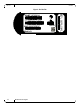
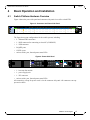
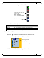
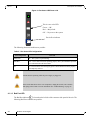
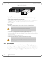
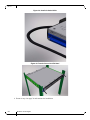
Figure 4 shows the power side panel and connector side panel views of the switch EVB.
Figure 3: Connector and Power Side Panel
MT51336-EN-EVB
MGT
1
2 3
4
5
6
7
8
9
10
11
12
13
14
15
16
17
18
19
20
21
22
23
24
25
26
27
28
29
30
31
32
33
34
35
CONSOLE
36
PS1
UID
RST
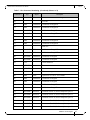
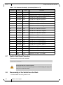
The figure shows port configurations for the switch systems, including:
•
2 – Ethernet RJ45 connectors
•
1 – RJ45 connector for connecting to a host PC (CONSOLE)
•
1 – USB connector
•
24 QSFP ports
•
12 SFP+ ports
•
various switch, port, fan and power status LEDs
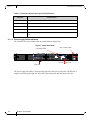
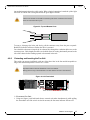
Figure 4: Power Side Panel
OK
OK
!
!
OK
!
I2C
Mellanox
•
1 – hot-swap fan module
•
1 – power supply unit
•
1 – I2C connector
•
various switch, port, fan and power status LEDs
All connectivity except for power cords is via the connector side panel. All connectors can support active cables.
Mellanox Technologies
15
!