1
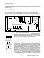
AIN
AOUT
DIN
DOUT
SERIN
SEROUT
EXRES W
SHUTTER
CONST-CURR
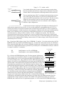
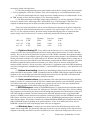
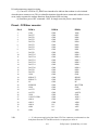
Analog inputs, 5-15. The input range of 5-7 is described on page 4-1, and the
remaining ones all have an input range of -3 to +3 volts.
Analog output 0-4. AIN0-1 are high current, unipolar outputs for driving heaters from
0 to -10 volts, while AIN2-3 are low current, bipolar outputs of -5 to +5 volts.
Digital inputs from 0 to 15. These are read every millisecond and stored in the DSP
data memory space. They have resistors to pull them high if not connected.
Digital outputs from 0 to 15. These are written from DSP data memory every
millisecond. They are pulled up so they will be high until set by the DSP.
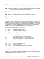
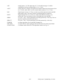
Two pins, + and -, for an asynchronous serial link generated by a 2681 chip. The two
inputs are optically isolated from the board.
Two pins, + and -, for an asynchronous serial link generated by a 2681 chip.
An input signal that will reset the DSP if brought low.
An open-collector output signal generated by this board. Low means open shutter.
A constant current source for CCD temperature control. See Fig. 4-3.
4-12
Utility board - Updated May 12, 1994