1
Contents
___________________________________________________________
Preface........................................................................................................... 1
1
Introduction ......................................................................................... 3
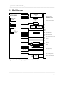
1.1 Block Diagram ............................................................................. 6
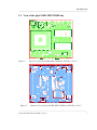
1.2 View of the phyCORE-MPC5200B tiny...................................... 7
1.3 Minimum Requirements to Operate the phyCORE-MPC5200B
tiny................................................................................................ 8
2
Pin Description .................................................................................... 9
3
Jumpers ..............................................................................................19
4
Power Requirements.........................................................................23
4.1 Voltage Supervision and Reset ..................................................24
5
System Start-Up Configuration .......................................................25
6
System Memory.................................................................................27
6.1 Flash Memory ............................................................................28
6.2 DDR SDRAM ............................................................................30
6.3 Serial Memory............................................................................31
7
Real-Time Clock RTC-8564 (U5) ....................................................33
8
Serial Interfaces.................................................................................35
8.1 RS-232 Interface ........................................................................35
8.2 Ethernet Interface .......................................................................36
8.2.1 PHY Physical Layer Transceiver .................................. 36
8.2.2 MAC Address................................................................37
8.3 USB 1.1 Host Interface ..............................................................38
9
The U-Boot Boot Loader ..................................................................39
9.1 U-Boot Default System Configuration....................................... 40
9.2 System Resources Required by U-Boot ..................................... 41
9.2.1 The "Backup" U-Boot ...................................................41
9.3 Modifying the U-Boot Loader....................................................44
10 JTAG Interface..................................................................................45
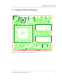
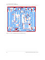
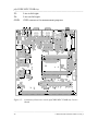
11 Component Placement Diagram......................................................47
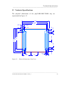
12 Technical Specifications....................................................................49
13 Hints for Handling the Module........................................................53
14 The phyCORE-MPC5200B tiny on the Carrier Board................. 55
14.1 Concept of the Carrier Board phyCORE-MPC5200B ............... 55
14.2 Carrier Board phyCORE-MPC5200B tiny Connectors and
Jumpers.......................................................................................57
14.2.1 Connectors.....................................................................57
14.2.2 Jumpers on the Carrier Board phyCORE-MPC5200B
tiny.................................................................................60
14.3 Functional Components on the phyCORE-MPC5200B tiny
Carrier Board..............................................................................63
14.3.1 Power Supply at X6 ......................................................63
___________________________________________________________________________________
© PHYTEC Messtechnik GmbH L-678e_3