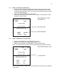
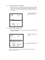
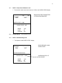
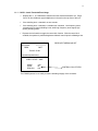
1
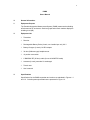
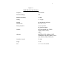
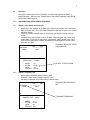
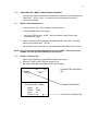
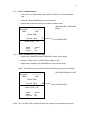
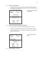
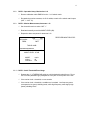
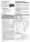
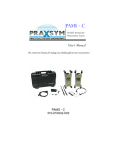
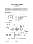
User’s Manual For
PAMS
Portable Attenuation Measurement System
www.praxsym.com
217/897-1744
2
Contents
I. Introduction .. .................................................................................................................................. 3
1.0
General Information................................................................................................................. 4
1.1
1.2
1.3
Equipment Purpose .....................................................................................................4
Equipment List.............................................................................................................4
Specifications ..............................................................................................................4
2.0
Installation..............................................................................................................................7
2.1
Recharging PAMS Units ............................................................................................7
2.2
Safety/Handling..........................................................................................................7
3.0
Operation ...............................................................................................................................8
3.2.0 “SEAM-SNIFFING” OPERATIONAL SEQUENCE.....................................................8
3.2.1 TRANS – Initial Setup and Power-On..............................................................8
3.2.2 TRANS – Frequency Set .................................................................................8
3.2.3 RCVR – Initial Setup and Power-On................................................................9
3.2.4 RCVR – Set Receiver Frequency = Xmit Frequency.......................................9
3.2.5 RCVR – Perform Cal........................................................................................10
3.2.6 TRANS – Set Atten to Operate Level ..............................................................10
3.2.7 RCVR – Verify Post-Calibration Level .............................................................11
3.2.8 SHIELDED ROOM – Close Enclosure Door....................................................11
3.2.9 RCVR – Read Shielding Level.........................................................................11
3.2.10 RCVR – Audio Threshold/Tone Usage ..........................................................12
3.3.0 “MONITOR (TS-31) MODE” OPERATIONAL SEQUENCE.......................................13
3.3.1 TRANS – Setup and Power-On .......................................................................13
3.3.2 TRANS – Frequency Set .................................................................................13
3.3.3 RCVR – Calibration Set-Up .............................................................................14
3.3.4 RCVR – Set Receiver Frequency = Xmit Frequency.......................................14
3.3.5 RCVR – Perform Calibration............................................................................15
3.3.6 TRANS – Attach Ant, Set Atten to Operate Lev ..............................................15
3.3.7 SHIELDED ROOM – Close Door.....................................................................16
3.3.8 RCVR – Operat. Set up, Monitor Ant. 1-12......................................................16
3.3.9 RCVR – Monitor Measurement, Antennas 1-12 ..............................................16
3.3.10 RCVR – Audio Threshold/Tone Usage ...........................................................17
3.4.0 “ BROADBAND MODE” SNIFFING OPERATIONAL SEQUENCE............................17
3.4.1 TRANS – Setup and Power-On .......................................................................17
3.4.2 SPECTRUM ANALYZER – Sniffing Measurements........................................18
4.0
Test and Inspection ...............................................................................................................19
4.2.1 TRANS – Setup and Power-On .......................................................................19
4.2.2. TRANS – Frequency Set to 904.2 MHz ...........................................................19
4.2.3 RCVR – Setup and Power-On .........................................................................19
4.2.4 RCVR – Set RCVR Freq equal to XMIT Freq ..................................................19
4.2.5 RCVR – Perform Cal........................................................................................19
4.2.6 TRANS – Set Atten to Operate Level ..............................................................19
4.2.7 RCVR – Read Post-Calibration Level ..............................................................19
4.2.8 TRANS – Set Atten to Operate Level ..............................................................19
4.2.9 RCVR – Read Operation Level........................................................................19
3
Introduction
The Portable Attenuation Measurement System (PAMS) is designed to measure the
shielding effectiveness of RF enclosures. The operational concept of PAMS is based
upon the measurement methodology outlined in MIL-STD-285.
Chapter 1.0 (General Information) provides:
9
The overall function and purpose of the equipment
9
A listing of included equipment
9
Specifications
Chapter 2 (Installation) describes site selection, unpacking and handling, power
requirements, safety procedures, preparation for reshipment and a listing of
recommended accessories.
Chapter 3 (Operation) describes operational sequences necessary to perform
required certification and verification.
Chapter 4 (Test and Inspection) describes tests, which may be conducted to verify
correct system operation.
4
PAMS
User’s Manual
1.0
General Information
1.1
Equipment Purpose
The Portable Attenuation Measurement System (PAMS) measures the shielding
effectiveness of RF enclosures. Both bar graph and numeric readout display the
shielding level (dB).
1.2
1.3
Equipment List
9
Transmitter
9
Receiver
9
Rechargeable Battery Packs (2 each, one installed per unit,) 9.6 V
9
Battery Chargers (2 each) / AC/DC Adapter
9
32 ohm (Walkman type) headphone set
9
12 position coax switch
9
6’ BNC/BNC RF (50 ohm) cable (for use in MONITOR mode)
9
Antennas (2 each), extended ¼ wavelength
9
Transit case
9
User’s manual
Specifications
Specifications for the PAMS transmitter and receiver are tabulated in Figures 1-1
and 1-2. Overall systems specifications are presented in Figure 1-3.
5
Figure 1-1
PAMS Receiver Specifications
Frequency
864-936 MHz
Detection Mode(s)
CW
Measurement Range
>110dB
Stability
+/- 2.5 ppm
Charger
at power jack
AC, 95-250 VAC, 47-63 Hz
DC, 15V +/-1.0V
Battery Operation
4 hours operation
90 minutes recharge
Controls
OFF/VOL, MODE, CAL, FREQ,
TUNE, T’HOLD, LOCK,
LIGHT
Indicators
BATTERY LEVEL, SIGNAL LEVEL,
THRESHOLD SETTING, MODE, LOCK,
CAL STATUS, FREQ, FREQ ADJ
Headphone Imped.
32 ohms
Weight
5.5 lbs.
Size
11.7” H x 5.1”D x 4.9”W
6
Figure 1-2
PAMS Transmitter Specifications
Frequency
864-936 MHz
Output Power
1 watt (CW mode)
-12 dBm (Broadband mode)
Operating Modes
CW, Combline (750-1000 MHz)
25 MHz steps
Attenuation
0 to 60 dB in 10 dB steps
Stability
+/-2.5 ppm
10kHz ten years
Charger
at power jack
AC, 95-250 VAC, 47-63 Hz
DC, 15V +/-1.0V
Battery Operation
2 hours operation
90 minutes recharge
Controls
OFF/ON, MODE, ATTEN, FREQ,
TUNE, LOCK, LIGHT
Indicators
BATTERY LEVEL, OUTPUT POWER,
MODE, LOCK, ATTEN LEVEL, FREQ
Weight
5.5 lbs.
Size
11.7” H x 5.1”D x 4.9”W
7
Figure 1-3
PAMS Overall System Specifications
1
End-to-End:
Dynamic Range
140 dB1
Meas. Accuracy
+/- 2 dB (-110 to 0 dBm)
User Interface
Full Alpha-numeric Backlit
LCD Display
Dynamic range is defined as the ratio (in dB) of maximum transmit power to receiver noise floor.
8
2.0
Installation
The PAMS is normally shipped (and transported) in a shock resistant transit case.
Batteries for the transmitter and receiver are already contained inside the respective
units.
2.1
Recharging the PAMS Units
Remove the battery chargers from the transit case. Plug the recharge jack into the
recharge receptacle on the right side of the PAMS Transmitter (or Receiver). Plug the
charger line cord into an AC source (95-250 VAC, 47-63 Hz). The green CHARGE light
on the front face of the PAMS unit should illuminate. When the unit is fully charged, the
CHARGE light should begin flashing.
When the units are fully charged, remove the charging jack from the PAMS unit. Unplug
the chargers and the receptacle line cords from the AC supply and return them to the
transit case.
If it becomes necessary to remove or replace the NiCad battery pack:
2.2
9
locate the bottom face of the unit, which houses the battery compartment cover
9
remove 4 socket head screws from battery cover bumper
9
remove the 4 Phillips head screws from the battery cover
9
remove the battery cover and disconnect the 2 pin connector
9
slide the battery out of the compartment
Safety/Handling
The PAMS system has been designed to survive in-field usage, however the following
handling restrictions should be observed:
9
Do not drop the units.
9
Protect the units from electrostatic discharge.
9
Do not connect high power (>1W) RF sources to the BNC connectors.
9
Do not connect DC sources to the BNC connectors.
9
3.0
Operation
This section describes the actions necessary to operate the PAMS in the SNIFF or
MONITOR mode. Within the text, TRANS refers to the PAMS Transmitter, while RCVR
refers to the PAMS Receiver.
3.2.0
SEAM-SNIFFING OPERATIONAL SEQUENCE
3.2.1
TRANS - Initial Setup and Power-On
Attach one of the antennas to the BNC jack located on the top face of the transmitter.
Open enclosure door. Place the PAMS Transmitter inside the enclosure on a marked
reference position.
9 Power-On / Rotate POWER switch to ON position and allow a 5 minute warm-up
period.
9 Confirm that the output power is set to –30 dBm. Depressing the “Attn” switch sets
output power. Each time the Attn switch is depressed, 10dB is added to the output.
Once 60 dB of attenuation is added, depressing the switch again will set the output
attenuator to 0 dBm.
TRANSMITTER INITIAL STATE
Low
Chg
ON POWER UP
900.0 MHz
------------------FREQ
BATT
9
9
=
-30
-10
+10
POWER OUT: -30 dBm
MODE:
ATTEN:
LOCK:
FRQ ADJ:
3.2.2
+30
OUTPUT ATTENTUATION
cw
60 dB
off
coarse
TRANS - Frequency Set
9
9
9
Adjust rotary LOW/HIGH (coarse) FREQ control
Depress F. DIGIT switch, FR ADJ toggles to “fine”.
Set rotary LOW/HIGH (fine) FREQ control (100kHz steps)
879.4 MHz
FREQ
=
-30
Low
Chg
------------------BATT
-10
+10
POWER LEVEL (dBm)
MODE:
ATTEN:
LOCK:
FRQ ADJ:
cw
60 dB
off
fine
+30
TRANSMITTER FREQUENCY
SET
TRANSMIT FREQUENCY
10
3.2.3
RVCR – Initial Setup and Power-On
9 Attach one of the antennas to the BNC jack located on the top face of the receiver.
9 Locate the receiver outside the enclosure on a marked reference position, at least
four feet from the transmitter. Make sure that the receiver reference position is within
view of the PAMS transmitter.
9 Power-On / Rotate POWER switch to ON position.
9 Confirm that the receiver is set to SNIFF mode. Depress the mode switch to rotate
through the receiver modes.
900.0 MHz
FREQ
Low
Chg
------------------BATT
RECEIVER INITIAL STATE
ON POWER UP
THOLD: 80dB
10
CAL NOT VALID
50
90
SHIELD LEVEL -- dB
MODE:
LOCK:
FRQ ADJ:
3.2.4
130
sniff
off
coarse
FLASHING TEXT
RECEIVER MODE
RCVR – Set Receiver Freq = Xmit Freq
9 Adjust rotary LOW/HIGH (coarse) FREQUENCY control
9 Depress F. DIGIT switch, the FR ADJ status toggles to “fine”.
9 Adjust rotary LOW/HIGH (fine) FREQUENCY control (100 kHz steps)
NOTE: The receiver frequency should be set to the same frequency as the transmitter.
879.4 MHz
FREQ
Low
Chg
------------------BATT
RECEIVER FREQUENCY SET
THOLD: 80dB
10
CAL NOT VALID
50
90
130
SHIELDING LEVEL dB
MODE:
LOCK:
FR ADJ:
FLASHING TEXT
sniff
off
fine
NOTE: The “INITIALIZE? PRESS CAL” warning will flash until a system level calibration
is performed.
11
3.2.5
RCVR – Perform System Level Calibration
9
Depress CAL switch. The “CAL NOT VALID” message is replaced by a shielding
level bar graph. The SHIELDING LEVEL display should read nominally 60 dB.
NOTE: The 60 dB shielding level indication offsets the 60 dB output attenuation on
the transmitter.
879.4 MHz
FREQ
Low
Chg
------------------BATT
RECEIVER AFTER SYSTEM
LEVEL CALIBRATION
===========
10
50
90
130
SHIELD LEVEL: 60dB
MODE:
LOCK:
FRQ ADJ:
3.2.6
sniff
off
fine
TRANS – Set Atten to Operate Level
9
Depress the ATTEN switch. The attenuator will advance from “60 dB” to the “0 dB”
setting (0-dB attenuation).
879.4 MHz
FREQ
Low
Chg
------------------BATT
TRANSMITTER OPERATE
LEVEL
============================
-30
-10
+10
+30
POWER OUT: +30 dBm
MODE:
ATTEN:
LOCK:
FRQ ADJ:
cw
0 dB
off
100kHz
OUTPUT ATTENUATION IS
0dB
NOTE: The transmitter output power at the BNC is +30 dBm (1 watt) when the
attenuator is set to 0 dB.
12
3.2.7
RCVR – Verify Post-Calibration Level
9
The Operator should read a level less than 10 dB on the SHIELD LEVEL display.
879.4 MHz
FREQ
Low
Chg
------------------BATT
RECEIVER AFTER TRANSMITTER
ATTENUATION REMOVED
SHIELD LEVEL <10dB
10
50
90
130
SHIELD LEVEL: 0dB
MODE:
LOCK:
FRQ ADJ:
sniff
off
fine
3.2.8
Shielded Room – Close Enclosure Door
3.2.9
RCVR – Read Shielding Level
9
The Operator reads SHIELD LEVEL display.
879.4 MHz
FREQ
Low
Chg
------------------BATT
===================
10
50
90
130
SHIELD LEVEL: 100dB
MODE:
LOCK:
FRQ ADJ:
sniff
off
fine
RECEIVER DISPLAYING
SHIELD LEVEL
SHIELDING LEVEL OF
ENCLOSURE
13
3.2.10 RCVR – Audio Threshold/Tone Usage
9 Depress the Å Æ THRESHOLD switches until the desired threshold is set. Plug a
Set of 32 ohm (Walkman-type) headphones in the jack on the top face of the unit.
9
If the shielding level > threshold, no tone sounds.
9
If the shielding level < threshold, a variable tone is emitted. Low frequency tones
correspond to low (poor) shielding levels, while high frequency tones signify high
(better) shielding levels.
9
Depress the lock switch to toggle the control lock function. With the control lock
enabled, the operator is protected against accidental control inputs invalidating a test.
879.4 MHz
FREQ
Low
Chg
------------------BATT
RECEIVER THRESHOLD SET
THOLD: 55 dB
==================
10
50
90
130
SHIELD LEVEL: 90dB
MODE:
LOCK:
FRQ ADJ:
sniff
off
fine
CONTROL LOCK STATUS
The PAMS Systems is now ready to test the shielding integrity of the enclosure.
14
3.3.0
“MONITOR (TS-31) MODE” OPERATIONAL SEQUENCE
9
3.3.1
Verify that the monitor antennas are installed and connected to the switch assembly
inputs ANT1 – ANT12. Note: The antennas are pre-installed on site and not
included in the PAMS.
TRANS - Setup and Power-On
9
Open enclosure door. Place transmitter inside enclosure.
9
Rotate POWER switch to ON position.
9
Verify that ATTEN is set to “60 dB.” Connect calibration cable END A to the
Transmitter BNC output.
9
Connect calibration cable (supplied with PAMS) END B to any of the 1x12 switch
matrix inputs (labeled ANT1 – ANT12).
9
Set the switch matrix select knob to couple calibration cable END B to the receiver.
NOTE: It is very important that the Output Power is set to -30dBm. Power levels above
+20dBm can cause permanent damage to the Receiver.
3.3.2
TRANS – Frequency Set
9
9
9
Adjust rotary LOW/HIGH (coarse) FREQ control (1 MHz steps)
Depress F. DIGIT switch, FRQ ADJ toggles to “fine”.
Set rotary LOW/HIGH (fine) FREQ control (100 kHz steps)
879.4 MHz
FREQ
=
-30
Low
Chg
------------------BATT
-10
+10
+30
POWER LEVEL: -30dBm
MODE:
ATTEN:
LOCK:
FRQ ADJ:
cw
60 dB
off
fine
TRANSMITTER FREQUENCY
SET
TRANSMIT FREQUENCY
STATUS OF TUNE SWITCH
15
3.3.3
RCVR – Calibration Setup
9
Connect the 1x12 switch matrix output (labeled “TO RCVR”) to the receiver BNC
input.
9
Power-On / Rotate POWER switch to the ON position.
9
Depress the mode button until the LCD mode line reads monitor.
900.0 MHz
FREQ
Low
Chg
------------------BATT
RECEIVER SET TO MONITOR
MODE
THOLD: 80dB
10
CAL NOT VALID
50
90
130
MONIT LEVEL: --dB
MODE:
LOCK:
FR ADJ:
3.3.4
FLASHING TEXT
monitor
off
fine
RCVR – Set Receiver Freq = Xmit Freq
9 Adjust rotary LOW/HIGH (coarse) FREQUENCY control (1 MHz steps)
9 Depress F. DIGIT switch, the FR ADJ status toggles to “fine”.
9 Adjust rotary LOW/HIGH (fine) FREQUENCY control (100 kHz steps)
NOTE: The receiver frequency should be set to the same frequency as the transmitter.
879.4 MHz
FREQ
Low
Chg
------------------BATT
RECEIVER FREQUENCY SET
THOLD: 80dB
10
CAL NOT VALID
50
90
MONIT LEVEL: --dB
MODE:
LOCK:
FRQ ADJ:
130
FLASHING TEXT
monitor
off
fine
NOTE: The “CAL NOT VALID” warning will flash until a system level calibration is performed.
16
3.3.5
RCVR – Perform Calibration
9
Depress CAL switch. The “CAL NOT VALID” message is replaced by a monitorlevel bar graph, which indicates that the reference level is 0 dB. The MONIT LEVEL
numeric display also reads 0 dB.
879.4 MHz
FREQ
Low
Chg
------------------BATT
RECEIVER AFTER MONITOR
CALIBRATION
THOLD: 80dB
10
SHIELD LEVEL < 0dB
50
90
130
MONIT LEVEL: 0dB
MODE:
LOCK:
FRQ ADJ:
3.3.6
monitor
off
fine
TRANS – Attach Antenna, Set Atten to Operate Level
9
Remove calibration cable END A from the transmitter BNC output connector.
9
Attach an omni-directional antenna (via cable) to the transmitter BNC output jack.
9
Depress the ATTEN switch. The attenuator mode will advance from 60 dB to the 0
dB setting (0 dB attenuation).
879.4 MHz
FREQ
Low
Chg
------------------BATT
==============
+28
+30
+32
POWER LEVEL: (dBm)
(+30dBm)
MODE:
ATTEN:
LOCK:
FRQ ADJ:
3.3.7
cw
0 dB
off
fine
SHIELDED ROOM - Close Door
TRANSMITTER OPERATE
LEVEL
17
3.3.8
3.3.9
RCVR – Operation Setup, Monitor Ant 1-12
9
Remove calibration cable END B from the 1 x 12 switch matrix.
9
Re-attach the monitor antennas, via 30-ft. cables, to each of the switch matrix inputs
(ANT 1 – ANT 12).
RCVR – Monitor Measurement, Antennas 1-12
9
Set the switch matrix to select “ANT 1.”
9
Read and manually record the MONIT LEVEL (dB).
9
Repeat the above sequence for antennas 2-12.
879.4 MHz
FREQ
Low
Chg
------------------BATT
RECEIVER MONITOR LEVEL
THOLD: 80dB
================
10
50
90
130
MONIT LEVEL: 87 dB
MODE:
LOCK:
FRQ ADJ:
monit
off
fine
3.3.10 RCVR – Audio Threshold/Tone Usage
9
Depress the Å Æ THRESHOLD switches until the desired threshold is set. Plug a
set of 32 ohm (Walkman-type) headphones in the jack on the top face of the unit.
9
If the monitor level > threshold, no tone sounds.
9
If the monitor level < threshold, a variable tone is emitted. Low frequency tones
correspond to low (poor) shielding levels, while high frequency tones signify high
(better) shielding levels.
18
3.4.0
“BROADBAND MODE” SNIFFING OPERATIONAL SEQUENCE
3.4.1
TRANS - Setup and Power-On
9
Attach antenna of suitable frequency range to transmitter BNC output.
9
Open enclosure door. Place unit inside enclosure.
9
Rotate POWER switch to ON position to begin transmitting.
9
Depress the MODE switch until the MODE status indicates the unit is in the “bb”
mode.
9
Depress the ATTEN switch. The ATTEN status reads “0 dB.”
900.0 MHz
FREQ
MODE:
ATTEN:
LOCK:
FRQ ADJ:
3.4.2
Low
Chg
------------------BATT
bb
0 dB
off
coarse
BROADBAND MODE
TRANSMITTER MODE
SPECTRUM ANALYZER – Sniffing Measurements
Operate the spectrum analyzer over a 750-1000 MHz band to search for leaking signals.
Signals generated by the broadband mode are available over the band at 25 MHz
intervals.
19
4.0
Test and Inspection
4.2.1
TRANS – Setup and Power-On
9
9
9
4.2.2.
TRANS – Frequency Set to 904.2 MHz
9
9
9
4.2.3
The operator should read a 0 dB level on the SHIELD LEVEL display.
TRANS – Set Atten to Operate Level
9
4.2.9
Depress the ATTEN switch. The attenuator will advance from “60 dB” to the “0 dB”
setting (0-dB attenuation).
RCVR – Read Post-Calibration Level
9
4.2.8
Depress CAL switch. The “CAL NOT VALID” message is replaced by a shielding
level bar graph. The SHIELD LEVEL display should read 60 dB.
TRANS – Set Atten to Operate Level
9
4.2.7
Adjust rotary (coarse) FREQUENCY control (1 MHz steps)
Depress switch, the FR ADJ status toggles to “fine”
Adjust rotary LOW/HIGH (fine) FREQUENCY control (100 kHz steps)
RCVR – Perform Cal
9
4.2.6
Place the RCVR on a table at a range of 10-20 feet from the Transmitter
Power-on / rotate POWER switch to ON position
RCVR – Set RCVR Freq equal to XMIT Freq
9
9
9
4.2.5
Adjust rotary LOW/HIGH (1 MHz steps) FREQ control
Depress F. DIGIT switch, FR ADJ toggles to “fine”
Adjust rotary LOW/HIGH (100 kHz steps) FREQ control
RCVR – Setup and Power-On
9
9
4.2.4
Place the unit on a table 3-5 feet high
Rotate POWER switch to ON position
Allow 5 minutes for warm-up
Depress the ATTEN switch until the attenuator setting reads “30 dB” (30 dB
attenuation).
RCVR – Read Operating Level
9
The operator should read a 30 dB +/- 2 dB on the SHIELD LEVEL display.
20
PAMSUSERSMAN
P/N 900-000001-001