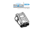
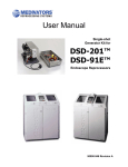
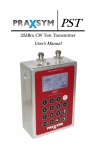
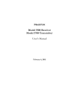
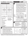
1
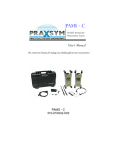
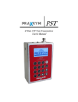
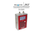
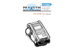
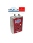
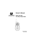
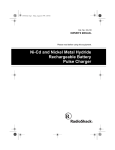
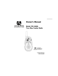
PAMS
Portable Attenuation
Measurement System
User’s Manual
The solution for making easy shielding effectiveness measurements
PAMS
310-010042-001
PAMS
TABLE OF CONTENTS
Warranty Statement
1
Chapter 1 General Information
2
•
•
•
•
Introduction
Equipment Purpose
Equipment List
Specifications
Chapter 2 System Care
•
•
•
•
Transportation
Recharging
Safety/Handling
Equipment Service
Chapter 3 Operation
•
5
7
Describes operational sequences necessary
to perform required certification and verification
♦
3.1 Receiver
♦
3.2 Transmitter
♦
3.3 Making Shield Level Measurements
♦
3.4 Using Broadband Mode
♦
3.5 Monitor Mode operational sequence
♦
3.6 Audio Threshold/Tone Usage
Warranty Statement
PRAXSYM warrants that all items will be free from defects in material and workmanship under use as
specified in this guide for a period of one year from date of delivery. PRAXSYM further agrees to repair
or replace, at its discretion, any failure which upon PRAXSYM's inspection appears to be a result of
workmanship or material defect. In no case, shall PRAXSYM's liability for breach of warranty exceed the
purchase price of the items in question. PRAXSYM's liability on any claim of any kind, for any loss connected with, or resulting from the use of, performance or breach thereof, installation, inspection, operation or use of any equipment furnished by PRAXSYM, shall in no case exceed the purchase price of the
goods which give rise to the claim.
Praxsym, Inc. P.O. Box 369 Fisher, IL 61843
217-897-1744 www.praxsym.com
Page 1
PRAXSYM
Chapter 1 General Information
Introduction
The Portable Attenuation Measurement System (PAMS) is designed to measure the shielding effectiveness of RF
enclosures. PAMS is a tool specifically engineered to enable regular maintenance of RF Shielded Enclosures. Routine
measurements can be made to ensure a baseline shield level is maintained with minimal disruption to normal activities
of the enclosure.
Equipment Purpose
The PAMS measures the shielding effectiveness of RF enclosures. Both bar graph and numeric readout display the
shielding level (dB). Separately, the transmitter and receiver will also work well in custom applications. The transmitter
provides a portable and semi-rugged CW transmitter with adjustable output power up to 1 Watt in the frequency range
from 864 MHz to 936 MHz. The receiver’s features allow it to make accurate signal level measurements in the presence
of high ambient wireless energy over a large dynamic range and as low as -120 dBm.
Equipment List
•
Transmitter
•
Receiver
•
Rechargeable Battery Packs (2 each, one installed per unit)
•
AC/DC power supply with cord, 15 VDC @ 3.4A (2 each)
•
32 Ω headphone set
•
12 position coax RF switch
•
6’ BNC/BNC RF (50 Ω ) cable
•
Antennas, extended 1/4 wavelength (2 each)
•
Transit Case
•
User’s Manual
Page 2
PAMS
PAMS Receiver Specifications
Frequency
864-936 MHz
Channel Spacing
100 kHz
Detection Mode
CW
Measurement Range
-120dBm to 0 dBm
Measurement Accuracy
+/-2 dB (-110 to 0 dBm)
Frequency Stability
+/- 2.5 ppm
Charge Voltage at Power Jack
DC, 15 +/-1.0 V @ 2A
Battery Operation
4 hours operation
70 minutes charge
Controls
OFF/VOL, MODE, CAL,
FREQUENCY SELECT
T’HOLD UP/DOWN,
LOCK, BACK LIGHT
Indicators
MODE, CAL STATUS,
SIGNAL LEVEL,
FREQUENCY, LOCK
THRESHOLD SETTING,
BATTERY CHARGE
User Interface
Full Alpha-numeric Backlit
LCD display
Operating Temperature
0°C to 40°C
Weight
5.5 lbs.
Size
11.7” H x 5.1” D x 4.9” W
Headphone Impedance
32 Ω
Page 3
PRAXSYM
PAMS Transmitter Specifications
Frequency
864-936 MHz
Channel Spacing
100 kHz
Operating Modes
CW, BROADBAND
CW Output Power
-30 dBm to +30 dB (CW)
Broadband Output
Combline with pickets at
25 MHz steps from 750 1000 MHz, -12dBm
Attenuation
0 to 60 dBm
1, 2, or 5 dB steps
Frequency Stability
+/-2.5 ppm
Charge Voltage at Power Jack
DC, 15 +/-1.0 V @ 2A
Battery Operation
2 hours operation
70 minutes charge
Controls
OFF/ON, MODE, ATTEN
FREQUENCY SELECT,
BACK LIGHT, LOCK
Indicators
MODE, FREQUENCY,
OUTPUT POWER,
ATTEN LEVEL,LOCK,
BATTERY CHARGE
User Interface
Full Alpha-numeric Backlit LCD display
Operating Temperature
0°C to 40°C
Weight
5.5 lbs.
Size
11.7” H x 5.1” D x 4.9” W
Page 4
PAMS
Chapter 2 System Care
Transportation
The PAMS is normally shipped (and transported) in a shock resistant
transfer case. Batteries for the transmitter and receiver are contained
inside the respective units.
Recharging the PAMS Units
To charge the battery pack inside the PAMS unit, plug the 2.5mm
female connector of the AC/DC 15 V power pack into the power receptacle on the right side of the PAMS Transmitter or Receiver. Plug
the charger line cord into an AC source (95-250 VAC, 47-63 Hz). The
green CHARGE light on the front face of the PAMS unit should illuminate during the entire fast charge cycle. The fast charge cycle of a
discharged battery will normally take less than 1.5 hours. When the
unit is fully charged, the CHARGE light will begin flashing indicating
the trickle charge phase. The trickle charger will continue to top-off
the battery pack until the AC/DC power pack is disconnected. Although this top-off process is normally completed in less than 6
hours, it can be left on overnight.
The battery may self-discharge to less than 3 Volts after a period of
storage or if the unit is left on for several days. During a new charge
cycle it will first enter a pre-charge trickle state before beginning the
fast charge phase. The green CHARGE light will flash during this
phase and then stay on continually once the fast charge phase has
begun. The pre-charge trickle phase can take anywhere form a few
seconds to 60 minutes dependent on the initial charge state. If the
fast charge state has not begun after several hours, the battery pack
should be replaced.
If a charge cycle is initiated on a fully charged battery, it is possible
that it will not be able to complete a normal charging cycle, illuminating the FAULT light. Although the FAULT light indicates that the
charge cycle was terminated, the trickle charge will continue to topoff the battery pack and it does not indicate a failure.
The FAULT light indicates that the charge process has been terminated. A FAULT light will be indicated with:
1. Excess supply input voltage
2. Very low battery voltage (indicate shorted cells)
3. Battery voltage low after 1/12th of charge timer
4. The charge is not normally terminated before the end of the cycle timer
Page 5
PRAXSYM
The OVERTEMP light indicates that the battery pack has exceeded its
maximum temperature during the charge process. When the OVERTEMP light is lit, the CHARGE light will be turned off indicating that
the charge process has been halted. Once the battery has cooled
down to an acceptable temperature, the charge cycle will resume.
If it becomes necessary to remove or replace the NiCad battery pack:
•
•
•
•
•
Locate the bottom face plate of the unit, which houses the battery compartment cover
Remove 4 socket head screws from the battery cover bumper
Remove 4 Phillips head screws from the battery cover
Remove the battery cover and disconnect the 2 pin connector
Slide the battery out of the compartment
Storing the PAMS Units
If the PAMS units will be stored for long periods between use (2-3
months), it is a good practice to disconnect the batteries to ensure
long battery life. With the batteries disconnected, they can be stored
charged or discharged. To disconnect the batteries, unplug the 2 pin
connector using the process described in the proceeding paragraph.
Safety/Handling
The PAMS system has been designed to survive in-field usage, however the following handling restrictions should be observed:
• Protect the units from electrostatic discharge
• Do not connect high power RF sources (>100 mW) to the input
BNC connector on the receiver. Always use a 30 dB in-line attenuator when connecting the transmitter directly to the receiver input.
• Do not connect DC sources to the BNC connectors
• The Receiver’s RF Input contains a DC bias voltage on the BNC
center pin for powering an external RF switch. Always use a DC
block when connecting the receiver to test equipment.
Equipment Service
Praxsym, Inc. provides repair and maintenance service.
Ph. 217-897-1744
www.praxsym.com
[email protected]
Page 6
PAMS
Chapter 3 Operation
3.1 Receiver
Receiver Modes
The receiver can be operated in one
of four different modes.
In Shield Level mode the receiver
can be used to measure the amount
of attenuation/shield level that is
provided by an enclosure or other
obstacles between the transmitter
and receiver. Before a shield level
test is conducted, the receiver is
initialized with the transmitter to
read 0dB shield level.
In Signal Strength mode the receiver can be
used to measure the signal level of a continuous wave signal. The receiver has a narrow
(+/-7.5 kHz) IF bandwidth enabling it
to measure a test signal in the presence of interfering signals in the same
band. Although the receiver has no
demodulation capabilities, it can be
used to measure the signal level of
narrow band modulated signals.
Shield Level Mode
In Spectrum Monitor mode the receiver can be used to view a 12 MHz
span of the frequency spectrum. This
mode is ideal for locating a clear frequency that you can use for conducting a test or for identifying large interfering signals that could cause errors
in measurements.
Spectrum Monitor Mode
Page 7
PRAXSYM
Monitor mode is included to emulate the function of the TS-31A
system. The TS-31A is the predecessor to PAMS. Monitor mode
uses the 12 position RF switch included with the PAMS. It also
makes use of up to 12 Ground Plane Antennas which are sold
separately.
Initial Set-Up and Power On
•
•
•
•
Attach one of the antennas to the BNC connector located on
the top of the receiver.
Power-On/Rotate POWER switch to ON position.
The receiver will power on in Signal Strength mode. To select
a different mode, depress the MODE switch to rotate through
Signal Strength, Spectrum Monitor, Shield Level, and Monitor
modes.
Allow the receiver to warm up for 5 minutes before taking
measurement data.
Set Frequency
•
•
•
•
•
The receiver always powers up tuned to 900 MHz.
Rotate the FREQUENCY adjust knob to tune the receiver in
1 MHz steps.
Depress the F.DIGIT switch to toggle the step size between
1 MHz and 100 kHz. The current step size is displayed on the
FR ADJ line of the display.
The frequency can be set in either Signal Strength or Shield
Level mode. The receiver will remain tuned to this frequency
as it is rotated through it’s modes of operation. In Spectrum
Monitor mode, this frequency will become the center frequency of the 12 MHz frequency span. Using the THOLD
arrow keys in Spectrum Monitor mode to move to a different
part of the spectrum will not effect the receiver frequency
when changing modes.
The Spectrum Monitor screen displays 12 MHz of signals at a
time from 864-936 MHz. Along the bottom of the screen the
start, center, and stop frequencies are displayed. The FREQUENCY select knob is used to move the marker across the
spectrum. The marker’s frequency and the measured signal
level at that frequency are displayed at the top of the display
screen. The THOLD arrows scroll through the 12 MHz spans
of the receivers frequency range.
Page 8
PAMS
Initializing Shield Level Measurements
In Shield Level mode the signal level measured by the receiver must
be initialized to the test signal from the transmitter to indicated 0 dB
shield level when the enclosure is open. This initialization process is
completed by depressing the CAL button. Details of the initialization
process are detailed in the “Making Shield Level measurements” section of the manual, section 3.3.
Backlight
Depress the LIGHT button on the top of the receiver to toggle the
LCD backlight on/off. Leaving the backlight on continuously will
decrease the battery operating time by approximately 10%.
Control Lock
Once set, the controls of the receiver can be locked to prevent inadvertently changing a setting that could result in measurement errors.
Depress the LOCK button on the top of the receiver to toggle the
lock feature on/off.
3.2 Transmitter
The transmitter is a continuous wave signal source with adjustable
output transmit level over it’s frequency range.
Initial Set-Up and Power On
•
•
•
Attach one of the antennas to the BNC connector located on the
top face of the transmitter.
Power On / rotate POWER switch to ON position.
Allow a 5 minute warm-up period before making measurements.
Page 9
PRAXSYM
Set the Output Level
The transmitter powers up in CW mode with the output level set to 30 dBm (60 dB attenuation). The output level of the transmitter is
adjusted by changing the attenuation level. -30 dBm output level
corresponds to 60 dB attenuation and +30 dBm (1 watt) corresponds
to 0 dB attenuation.
• Depress the ATTN button on the top of the transmitter to toggle
between 0 dB and 60 dB of attenuation.
• Depress the MODE button on the top of the transmitter to toggle
between the three operating modes: frequency adjust mode,
power adjust mode and broadband mode. In frequency adjust
mode (power up default), the transmitter output is a CW signal
and the output frequency is changed using the frequency control knob. In power adjust mode, the output level of the CW signal can be changed using the frequency control knob. Depressing the mode button a second time places the transmitter in
broadband mode. See Section 3.4 for a description of broadband
mode. The current setting of the mode button is displayed on
the LCD.
• In power adjust mode, depress the F. DIGIT button on the top of
the transmitter to rotate the increment of the FREQUENCY select
knob between 1, 2, and 5 dB steps.
Set Frequency
•
•
•
•
The transmitter always powers up tuned to 900 MHz.
Depressing the MODE button will take the transmitter to FR ADJ
mode, allowing for frequency adjustment to match the receiver.
Rotate the FREQUENCY adjust knob to tune the transmitter in
1 MHz steps.
Depress the F.DIGIT switch to toggle the step size between
1 MHz and 100 kHz. The current step size is displayed on the FR
ADJ line of the display.
Backlight
Depress the LIGHT button on the top of the transmitter to toggle the
LCD backlight on/off.
Page 10
PAMS
Control Lock
Once set, the controls of the transmitter can be locked to prevent
inadvertently changing a setting that could result in measurement
errors. Depress the LOCK button on the top of the transmitter to
toggle the lock feature on/off.
•
•
•
3.3 Making Shield Level measurements
Before making shield level measurements, turn on the transmitter and receiver, tune both units to the test frequency, set the
output of the transmitter to 60 dB attenuation, allow both units
to warm up for 5 minutes.
With the receiver in Signal Strength mode, monitor the test frequency to ensure no interfering signal is present on your test
frequency.
When making measurements in an unfamiliar area, set the receiver to Spectrum Monitor mode to determine frequencies in
the spectrum that are clear to use for testing your shielded enclosure.
The 60 dB shielding level indication offsets the 60 dB output attenuation on the transmitter. By placing the transmitter and receiver 4-5 feet apart, approximately 30 dB of free space path loss
exists. When calibrating the units, the receiver has been designed
to account for this amount of path loss in conjunction with the 60
dB of attenuation given by the transmitter. Thus, when the attenuation is removed from the transmitter, the receiver will read very
close to 0 dB shield level.
Page 11
PRAXSYM
•
•
•
•
•
•
•
•
With the transmitter and receiver both set to the same test frequency, place the transmitter inside the enclosure on a marked
reference position near the center of the enclosure. Ensure the
transmitter output level is set to -30 dB.
Place the receiver outside the enclosure on a marked reference
position, at least four feet from the transmitter. Ensure that the
receiver reference position is within line of sight of the transmitter.
Set the receiver to Shield Level mode, the receiver will flash
“INITIALIZE? PRESS CAL” on the display.
Ensure that there are no obstructions between the transmitter
and receiver and then depress the CAL button on the Receiver.
The display should indicate a Shield Level of 60 dB.
Return to the transmitter and depress the ATTN button. The attenuation will toggle to 0 dB and the transmitter is now at +30
dBm output.
Verify that the Shield Level reads less than 3 dB on the receiver.
This may vary slightly as every environment is unique. A reading
of 0 dB is ideal.
Close the door to the enclosure and begin sniffing with the Receiver.
The Receiver is now measuring and displaying Shield Level of the
enclosure.
Seam Sniffing in Shield Level Mode
Page 12
PAMS
3.4 Using the Transmitter’s Broadband Mode
In Broadband Mode, the output from the transmitter is a series of 25
MHz spaced pickets generated by a comb generator. These pickets
will vary in level between -10 dBm and -15 dBm over the frequency
range of 750-1000 MHz.
Broadband Mode is especially useful when testing smaller tabletop
enclosures. With the transmitter operating in the enclosure, a spectrum analyzer can be used to determine the shield level even if a
cavity resonance should fall within the band.
Transmitter Setup and Power ON
♦
Attach antenna of suitable frequency range to transmitter BNC
output.
♦
Open enclosure door. Place unit inside enclosure.
♦
Rotate POWER switch to ON position to begin transmitting.
♦
Depress the MODE switch until the MODE status indicates the
unit is in the “bb” mode.
♦
Depress the ATTEN switch. The ATTEN status reads “0 dB.”
♦
With the enclosure open, measure the level of the pickets with a
spectrum analyzer. Shield level can be determined by calculating the drop in picket level after the enclosure door is closed.
3.5 Monitor Mode Operational Sequence
Monitor mode can be used daily to monitor a relative reference level
to determine if a change in shielding effectiveness has occurred.
First, the shield level of the enclosure must be confirmed using the
shield level mode (see section 3.3). Monitor mode can be used with
a set of permanently installed antennas on each surface of the enclosure to ensure the shield level remains constant. Verify that the
monitor antennas are installed and connected to the switch assembly inputs ANT1 – ANT12. Note: The antennas are pre-installed on
site and not included in the PAMS.
A relative reference level must first be established to be used as a
baseline for daily comparison. Every time a monitor measurement is
to be made, the transmitter and receiver should be initialized using
the same procedure and coax cables that were used to establish the
baseline.
Page 13
PRAXSYM
Transmitter Setup
♦
Rotate POWER switch to ON position.
♦
Verify that ATTEN is set to “60 dB.”
♦
Set the transmitter frequency.
♦
Connect one end of the calibration cable (supplied with the
PAMS set) to the transmitter BNC output and the opposite end
to any of the 1x12 switch matrix inputs (labeled ANT1 –
ANT12).
♦
Set the switch matrix select knob to the antenna port that you
connected the transmitter to.
NOTE: It is very important that the Output Power is set to -30
dBm. Power levels above +20 dBm can cause permanent damage
to the Receiver.
Receiver Setup
♦
Connect the 1x12 switch matrix output (labeled “TO RCVR”) to
the receiver BNC input.
♦
Power-On / Rotate POWER switch to the ON position.
♦
Depress the mode button until the LCD mode line reads monitor.
NOTE: The “INITIALIZE? PRESS CAL” warning will flash until a
system level calibration is performed.
Perform Receiver Initialization
♦
Depress CAL switch. The “INITIALIZE? PRESS CAL” message is
replaced by a monitor-level bar graph, which indicates that
the reference level is 0 dB. The MONIT LEVEL numeric display
also reads 0 dB.
Configure Transmitter for Operation
♦
Disconnect the transmitter from the antenna switch and place
the transmitter inside of the enclosure.
♦
Reattach the permanently mounted antenna to the switch
port you were using.
♦
Attach an omni-directional antenna to the transmitter BNC
output connector.
♦
Depress the ATTEN switch. The attenuator mode will advance
from 60 dB to the 0 dB setting (0 dB attenuation).
♦
Close the enclosure door.
Page 14
PAMS
SHIELDED ROOM - Close Door
Begin Test in MONITOR mode
♦
Set the switch matrix to select “ANT 1.”
♦
Read and manually record the MONIT LEVEL (dB).
♦
Repeat the above sequence for antennas 2-12.
12 Position RF Switch
Page 15
PRAXSYM
•
•
•
•
3.6 Audio Threshold/Tone Usage
Depress the ←/→ THRESHOLD switches until the desired threshold
is set. Plug a set of 32 Ω headphones in the jack on the top face of
the unit.
If the shielding level is less than the threshold, a variable tone is
emitted. Low frequency tones correspond to low (poor) shielding
levels, while high frequency tones signify high (better) shielding
levels.
If the shielding level exceeds the threshold, no tone sounds.
Depress the lock switch to toggle the control lock function. With
the control lock enabled, the operator is protected against accidental control inputs invalidating a test.
Page 16
PAMS
Notes
Page 17
PRAXSYM
Notes
Page 18
PRAXSYM
123010 Rev E
900-000001-001