1
3. Set the thermostat fan mode to AUTO and verify the
blower stops running.
System Cooling
1. Set the thermostat’s system mode to COOL and the
fan mode to AUTO. Gradually lower the thermostat
temperature setpoint below room temperature and
verify the outdoor unit and indoor blower energize.
2. Verify blower wheel is spinning in direction indicated by
arrow. Feel the air being circulated by the indoor blower
and verify that it is cooler than ambient temperature.
Listen for any unusual noises. If unusual sounds
occur, determine the source of the noise and correct
as necessary.
3. Verify HI and LO refrigerant pressures.
4. Allow the system to operate for several minutes
and then set the temperature selector above room
temperature. Verify the fan and compressor cycle off
with the thermostat. NOTE: The blower should also
stop unless fan mode is set to the ON position.
System Heating (optional)
1. Set the thermostat's system mode to HEAT and the
temperature mode above room temperature.
2. Verify the optional heating equipment (furnace or
electric heat) and indoor blower energize. Feel the air
being circulated by the indoor blower and verify that
it is warmer than ambient temperature. Listen for any
unusual noises. If unusual sounds occur, determine
the source of the noise and correct as necessary.
Refrigerant Charging
WARNING:
JS5BD Split system air conditioners leave the
factory with a nitrogen holding charge. DO NOT
operate any unit while it contains a Nitrogen
holding charge. Doing so may damage the units
compressor. Follow these charging instructions
for maximum unit performance and efficiency.
Some local codes require licensed installation/
service personnel to service this type of
equipment. Refrigerant charging must be done
by qualified personnel familiar with safe and
environmentally responsible refrigerant handling
procedures. Under no circumstances should
the owner attempt to install and/or service this
equipment. Failure to comply with this warning
could result in property damage, personal injury,
or death.
To properly charge these units:
1. Read all Installation Instructions first.
2. Complete any brazing operations. (e.g. Split system
line-sets)
8
3. Leak check and evacuate the whole system using
proper methods.
4. Purge the nitrogen holding charge.
5. Evacuate the unit to 350-500 microns.
6. Allow the unit to remain under vacuum for at least 30
min.
7. Weigh-In the proper amount of new (or reclaimed)
R-22 refrigerant. Refer to Table 3 or the units rating
label to determine the correct amount of charge.
• Refrigerant charging charts are applicable only to
matched assemblies of NORDYNE equipment and
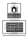
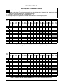
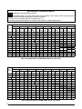
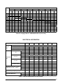
listed airflows for the indoor coil. Refer to Figures 5 11 (Pages 10 - 13) for correct system charging.
• JS5BD outdoor units with indoor coils not listed are
not recommended. Deviations from rated airflows or
non-listed combinations may require modification to the
expansion device and refrigerant charging procedures
for proper and efficient system operation.
• The refrigerant charge can be checked and adjusted
through the service ports provided external to the
outdoor unit. Use only gage line sets which have a
“Schrader” depression device present to actuate the
valve.
Charging an R-22 system in AC mode at outdoor temperatures above 55° F for optimized sub-cooling of 10°
F - 12° F.
1. With the system operating at steady-state, measure
the liquid refrigerant pressure (in psig) at the outdoor
unit service valve.
2. Measure the liquid refrigerant temperature (in
Fahrenheit) at the service valve.
3. Determine the required liquid refrigerant pressure.
Refer to Tables 4 - 10 (pages 14 - 17) for correct
system charging.
• If the pressure measured in Step 1 is greater than
the required liquid refrigerant pressure determined in
Step 3, then there is too much charge in the system.
Remove refrigerant and repeat Steps 1 through 3 until
the system is correctly charged.
• If the pressure measured in Step 1 is less than the
required liquid refrigerant pressure determined in
Step 3, there is too little charge in the system. Add
refrigerant and repeat Steps 1 through 3 until the
system is correctly charged.
Model
Number
Restrictor Bore
Size (inches)
System charge
R-22 (oz.)
018KA
024KB
030KB
036KB
042KA
048KA
060KA
0.053
0.060
0.065
0.075
0.078
0.089
0.099
78
53
56
68
122
126
160
Table 3. Refrigerant Metering Device
for 13 SEER Split System Air Conditioner