1
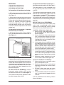
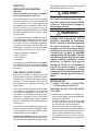
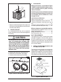
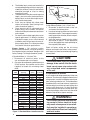
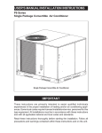
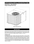
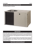
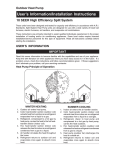
USER’S MANUAL AND INSTALLATION INSTRUCTIONS
13 SEER
Single Package Air Conditioner
Single Package Air Conditioner
IMPORTANT
Read this owner information to become familiar with the capabilities and use
of your appliance. Keep this with literature on other appliances where you
have easy access to it in the future. If a problem occurs, check the instructions
and follow recommendations given. If these suggestions don’t eliminate your
problem, call your installing contractor or distributor in your area.
INTRODUCTION
Most any air conditioner will keep you cool. Our air conditioner was designed to do
it efficiently. Efficiency means less cost to you while keeping you comfortable.
WHY YOUR AIR CONDITIONER WORKS SO WELL, SO QUIETLY
1.
Air is cooled by a large evaporator coil. Moisture is also removed from the air by
this same coil.
2.
Air is then delivered through the main duct, via registers, into your home.
3.
Return air is drawn through the return register.
4.
This air enters the unit, passes through the evaporator coil, is cooled and dehumidified. Then the cycle begins again.
2
SECTION 1.
OWNER INFORMATION
OPERATING INSTRUCTIONS
To Operate Your Air Conditioner for Cooling—
1. Set the thermostat system switch to COOL or
AUTO and the thermostat fan switch to AUTO.
(See Figure 1)
2. Set the thermostat temperature to the desired
temperature level using the temperature selector.
Please refer to the separate thermostat user’s
manual for complete instructions regarding
thermostat programming. The outdoor unit
and indoor blower will both cycle on and off to
maintain the indoor temperature at the desired
cooling level.
To OperateYour Unit for Heating — (If optional
heat accessory is installed.)
1. Set the thermostat system switch to HEAT or
AUTO and the thermostat fan switch to AUTO.
(See Figure 1)
Fan Switch
Temperature Selector
Figure 1. Typical Thermostat
2. Set the thermostat temperature to the desired
temperature level using the temperature selector.
Please refer to the separate user’s manual for
complete thermostat programming instructions.
The furnace and indoor blower will cycle on and
off to maintain the indoor temperature at the
desired heating level.
To Shut Off Your Air Conditioner —Set the
thermostat system switch to OFF and the
thermostat fan switch to AUTO. (See Figure 1)
The system will not operate, regardless of the
thermostat temperature setting.
To Operate the Indoor Blower Continuously—
Set the thermostat fan switch to ON (See Figure 1)
The indoor blower will start immediately, and
will run continually until the fan switch is reset
to AUTO.
The continuous indoor blower operation can be
obtained with the thermostat system switch set
in any position, including OFF. The continuous
indoor blower operation is typically used to
circulate the indoor air to equalize a temperature
unbalance due to a sun load, cooking, or fireplace
operation.
BEFORE YOU CALL A SERVICEMAN
Let your serviceman check your system at the
start of each air conditioning season. He will
make sure it’s working right, clean or change
filters and make any needed adjustments.
In addition, follow these simple rules:
1. Never run your system without filter. If you
do, the cooling coils will get dirty and may
become clogged.
2. Set your thermostat at the comfort level you
wish -- and then leave it alone. Let it control
the operation of the air conditioning system.
If you get chilly, turn it up a degree at a time
until comfort is restored.
3. It takes longer for an air conditioner to cool
your dwelling than it does for your furnace to
heat it. Therefore, do not turn the unit on and
expect a dramatic drop in temperature, at
least not right away. If your home is hot and
humid, the temperature will drop slowly.
4. Check your filters every ten days in summer
to see if they are dirty. To keep them clean,
use a mild solution of detergent and water
on washable types. Replace non washable
filters.
5. Keep your outdoor condenser coil clean.
You can hose it down when it gets dirty.
If your air conditioner isn’t working:
1. Make sure the fuses are not blown or that
your circuit breakers are on.
2. See that your thermostat is set at the desired
temperature and that your system’s switch
is on “Cool.”
3. For free air flow, make sure your return
register is not covered and that the filter is
clean.
4. Check the outdoor condenser coil and make
sure it is clean and not clogged with grass
or leaves.
If your air conditioner still isn’t working, call your
nearest distributor.
3
SECTION 2.
INSTALLER INFORMATION
GENERAL
Read the following instructions completely
before performing the installation.
These instructions are for the use of qualified
personnel specially trained and experienced
in the installation of this type of equipment
and related system components. Some states
require installation and service personnel to
be licensed. Unqualified individuals should not
attempt to interpret these instructions or install
this equipment.
The single packaged air conditioners are designed for outdoor installation only and can be
readily connected into the high static duct system
of a home. The only connections needed for
installation are the supply and return ducts, the
line voltage, and thermostat wiring. A complete
air conditioning system typically consists of:
• Single Package Air Conditioner
• Home Fittings Kit
• Unit Fittings Kit
• Thermostat
The single package air conditioner is completely
assembled, factory wired, and factory run tested.
The units are ready for easy and immediate
installation.
PRE-INSTALLATION CHECK
Before any installation is attempted, the cooling load of the area to be conditioned must be
calculated and a system of the proper capacity
selected. It is recommended that the area to
be conditioned be completely insulated and
vapor sealed.
The installer should comply with all local codes
and regulations which govern the installation
of this type of equipment. Local codes and
regulations take precedence over any recommendations contained in these instructions.
Consult local building codes and the National
Electrical Code (ANSI CI) for special installation
requirements.
The electrical supply should be checked to determine if adequate power is available. If there
is any question concerning the power supply,
contact the local power company.
Inspecting Equipment: All units are securely
packed at the time of shipment and, upon arrival,
should be carefully inspected for damage. Claims
4
for damage (apparent or concealed) should be
filed immediately with the carrier.
CAUTION:
This unit uses refrigerant R-410A. Do
NOT under any circumstances use
any other refrigerants besides R-410A
in this unit. Use of another refrigerant
will damage this unit.
WARNING:
Single Packaged Air Conditioners are
shipped fully charged with R-410A
refrigerant and ready for installation.
When a system is installed according
to these instructions, no refrigerant
charging is required. If repairs make it
necessary for evacuation and charging,
it should only be done by qualified,
trained personnel thoroughly familiar
with this equipment. Some local codes
require licensed installation service
personnel to service this type of
equipment. Under no circumstances
should the owner attempt to install
and/or service this equipment. Failure
to comply with this warning could result
in property damage, personal injury or
death.
INSTALLATION
1.
SELECT THE BEST LOCATION FOR
THE AIR CONDITIONING UNIT
IMPORTANT: DO NOT PLACE UNIT UNDER
THE HOME.
• Select a solid, level position, preferably on a
concrete slab, slightly above the grade level,
and parallel to the home.
• The hot condenser air must be discharged
up and away from the home, and if possible,
in a direction with the prevailing wind.
• Do not place the unit in a confined space.
• If practical, place the air conditioner where it
and the ducts will be shaded from the afternoon sun when the heat load is greatest.
• Try to select a site for the unit that is as close
as possible to the proposed return grille location.
3.
CLEARANCES
6 ft.
Minimum clearances, as specified in Figure
2, MUST be maintained from adjacent structures to provide room for proper servicing
and air circulation.
24"
Do NOT install unit in a confined or recessed
area that will allow discharge air from the unit
to re-circulate into the condenser air inlet,
through the coil.
12"
12"
Figure 2. Minimum Unit Clearances
• Keep in mind that the length of the supply and
return ducts should be kept to a minimum with
no sharp radius bends.
2. UNPACK THE UNIT
It is recommended that the unit be unpacked
at the installation site to minimize damage due
to handling.
CAUTION:
Do not tip the unit on its side. Oil may
enter the compressor cylinders and
cause starting trouble. If unit has been
set on its side, restore to upright position and do not run for several hours.
Then run unit for a few seconds. Do this
three or four times with five minutes
between runs.
a. Remove the bands from around the unit.
b. Unfold the top and bottom cap flanges.
c. Carefully remove the top cap and tube.
Transition Duct Screws
Supply Air
Service Access Clearance:
Blower access panel side ...........................24”
Electrical compartment access panel side .. 12”
Clearance between overhang and top of
unit .............................................................72”
Clearance around condenser coil area to wall
or shrubs (excludes duct panel side) ..........12”
Minimum clearance to combustible materials:
Combustible Base (Wood or Class A, B, or C
roof Covering material) .............................. 0”
Supply and Return Air Ducts ...................... 0”
Duct Connection side ................................. 0”
DUCT REQUIREMENTS
The supply duct system, including the number
and type of registers, will have much more effect on the performance of an air conditioning
system then any other factor. The duct must be
sufficiently large to conduct an adequate amount
of air to each register.
4.
INSTALLTHE RETURN AND SUPPLY AIR
FITTINGS ON THE UNIT
The supply and return fittings are included with
select models. If supplied, the duct fittings are
shipped in the supply duct.They attach to the unit
openings with a flange and bead arrangement,
secured with two sheet metal screws. Note: For
14” Duct Dimples
Return Air
Figure 3. Return and Supply Air Fittings
Figure 4. Return Air Box
5
ease of access, install fitting before positioning
unit in final location.
SUPPLY DUCT
Position the supply duct collar, if supplied, so the
edge of the unit opening fits between the flange
and the bead. Overlap the collar ends keeping the
small screw holes underneath. Align the holes in
the crimped area and install one screw.
Note: It may be necessary to loosen the four
screws that hold the transition duct in order to
install the supply fitting. Re-tighten when installation is complete.
Tap collar as necessary to ensure engagement
with unit opening and install second screw.
Tighten first screw. Rotate collar clockwise so
joint is near three o’clock position.
RETURN DUCT
Align the 14” return duct slots with the holes in
the collar and install two screws. Position the
collar over the opening and align the four notches
in the collar with the four dimples in the panel.
Using self-drilling screws (10-16x.5) attach the
collar to the rear panel.
5.
LOCATING AND INSTALLING THE RETURN AIR ASSEMBLY
To avoid complications, locate and install the
return air assembly first. The return air box
with grille and filter (Figure 4) should not be
located in heavy traffic areas like hallways or
center of rooms. A good spot is in a corner or
under a table, if a minimum two inch clearance
is available. If desired, the return opening can
be located inside a closet with louvered doors
that have an open area equal to or greater than
the 12” x 20” grille furnished. The return air grille
can be placed in the wall of a closet and the air
ducted into the filter box through a boxed-in area
at the closet floor level. Make sure the filter is
readily accessible.
After determining the location of the return air
opening, start the installation from under the
home by cutting a small hole in the fiber underboard to determine how the floor joist location
will affect cutting the opening needed for the box.
Floor joists generally are located on 16” centers,
leaving 14-3/8” between joists. After measuring
the return air box (approximately 12-1/4” x 141/4”), cut the hole through the floor so that the
box will fit between the floor joists. Care should
be taken when cutting through carpeting to avoid
snags. In most installations it will be necessary to
cut a similar hole in the fiberboard directly under
the hole in the floor. However, if the floor is more
than ten inches deep, it will only be necessary
6
Figure 5. Supply Damper
to cut a hole for the collar on the return air box
or for the insulated duct.
Set the box into the opening and fasten with
screws or nails. Put the filter and return air
grille in place.
6.
LOCATING AND INSTALLING THE
SUPPLY DAMPER(S)
CAUTION:
When a home is not equipped with a
make-ready kit, means must be provided to prevent simultaneous operation of the heating and cooling units.
A heat/cool thermostat is available for
this purpose.
When installing this air conditioning
system in conjunction with a furnace, a
damper must be installed in the furnace
base assembly to prevent cold air being
discharged around the heat exchanger.
Damage to the heat exchanger and
asphyxiation may occur if a damper is
not installed.
Check with the furnace manufacturer
for damper requirements. Failure to
install the required furnace damper
may invalidate code agency listing and
limited warranty on the furnace.
When locating the supply damper(s), carefully
check floor joists and frame members that could
interfere with the installation of the damper or
flexible duct. Ideally, the damper should be
located in the bottom of the main duct, forward
of center of the home, at least three feet from
the nearest register. The round supply opening
in the slanted side of the damper should face
the side of the home where the air conditioner
is located. To locate the center of the heat duct,
first cut a small hole in the fiberboard below the
TYPICAL APPLICATIONS
4
4
6
3
2
3
2
6
4
6
7
1
1
5
5
SINGLE DUCT APPLICATION
Ref. No.
1
2
3
4
5
6
7
MULTIPLE DUCT APPLICATION
Description
12” x 20” Return Air
16” x 20” Air Filter
12” x 20” Grille
Supply Damper
14” Diameter Flex Return Duct
12” Diameter Flex Supply Duct
12” x 12” x 12” “Y” Fitting
Figure 6. Typical Applications
duct at the desired location. After locating the
duct center, cut a hole approximately 3/4” larger
than the damper opening in the fiberboard. Cut
a 9-1/8” x 13-1/8” hole in the duct and bend
over all tabs flat on the inside of the heat duct.
After inserting the damper into the duct, bend
over all tabs flat on the inside of the heat duct.
Seal the opening between the fiberboard and
damper or flexible duct.
DUCTING SYSTEM
90A), “Standard for Installation of Residence
Type Warm Air Heating and Air Conditioning
Systems” (NFPA 90B), these instructions, and
all applicable codes.
THE AIR CONDITIONING OUTPUT OF THE
SYSTEM WILL NOT COOL THE HOME IF THE
AIR IS LOST TO THE OUTSIDE THROUGH
LEAKS INTHE DUCT SYSTEM. ALSO, DUCTS
WHICH ARE COLLAPSED OR RESTRICTED
BY FOREIGN OBJECTS WILL PREVENT
ADEQUATE AIR FLOW.
DUCT REQUIREMENTS
The supply duct system, including the number
and type of registers, will have much more effect on the performance of an air conditioning
system than any other factor. The duct must be
sufficiently large to conduct an adequate amount
of air to each register.
Note: For highly resistive duct systems it may
be necessary to add an additional return air duct
and or supply to achieve maximum performance
and prevent coil icing and refrigerant flood
back.
Air ducts should be installed in accordance with
the standards of the National Fire Protection
Association “Standard for Installation of Air
Conditioning and Ventilation Systems” (NFPA
a.
CONNECTING THE RETURN AND SUPPLY
AIR FLEXIBLE DUCTS
The supply duct for all units is 12” in diameter. The return duct is 14” diameter for all
air conditioning units.
7
b.
The flexible ducts can be connected to the
corresponding fittings with the clamps provided with the ducts. Note: All connections
should be leak tight or a loss in cooling
capacity will result.
The flexible ducts may be cut to the required
length, see instructions packed with duct.
Keep all ducts as short and straight as possible. Avoid sharp bends.
Ducts may be spliced with sheet metal
sleeves and clamps. (See Ducting Installation Accessories page 6.)
Once the inner duct is connected to the
proper fitting, the insulation and plastic
sleeve should be pulled over the connection
and clamped.
For homes with multiple supply ducts or for
special applications, a Y fitting is available
to divide the supply air so it can be ducted
to different areas of the home for more efficient cooling. Note: The Y fitting should be
insulated for maximum performance.
If High Efficiency Motor (3.5, 4, and 5 Ton):
1. Disconnect all electrical power to the unit
and remove the blower panel.
2. Locate the orange and red wires terminated
to the blower motor. The orange wire controls
cooling operation while the red wire controls
heating operation.
3. Verify the required speed from the airflow
data found in figure 7. Place appropriate
wire on the appropriate motor speed tap for
the required airflow point.
Blower Speed — For optimum system
performance and comfort, it may be necessary
to change the factory set speed. See figure 7 for
factory settings. To change the blower speed:
Check all factory wiring per the unit wiring
diagram and inspect the factory wiring connections to be sure none loosened during shipping
or installation.
c.
d.
e.
f.
If Standard Motor (2, 2.5 and 3 Ton):
1. Disconnect all electrical power to the
unit and remove the service panel.
2. Place the desired blower speed lead on the
“COM” terminal. Use another wire tie (field
supplied) to bundle the remaining motor
leads.
Model
P5RD
2 Ton
2.5 Ton
3 Ton
3.5 Ton
4 Ton
5 Ton
Wire Color /
Speed Tap
Motor
Speed
Air Flow
(0.3 In. WC)
Red
Black
Red
Black
Red
Black
T1
T2
T3
Orange / T4
Red / T5
T1
Red / T2
Orange / T3
Low*
High
Low
High*
Low
High*
Low
Med/Low
Medium
Med/High*
High*
Low
Med/Low*
Medium*
770
1064
770
1064
770
1064
750
1000
1140
1300
1450
1340
1450
1500
T4
Med/High
1650
T5
T1
Red / T2
T3
Orange / T4
T5
High
Low
Med/Low*
Medium
Med/High*
High
1970
1340
1450
1500
1650
1970
* Factory Setting
Figure 7. Standard Motor Lead Connection
8
Elbow
P-Trap
Figure 8. Drain Trap
CAUTION:
To avoid personal injury or property
damage, make certain that the motor
leads cannot come into contact with
any uninsulated metal components
of the unit.
CONDENSATE DRAIN
A 3/4” condensate fitting extends out of the side
of the unit.The drain trap, shipped in the electrical
compartment, must be installed to prevent water
from collecting inside the unit. Thread the elbow
provided with the unit into the drain connection
until hand tight. Install the trap into the fitting and
seal the joint. Make sure it is level. Route the
condensate from the trap to a suitable drain. Any
connecting tubing or hose must have the outlet
below the trap level for proper drainage.
WARNING:
Turn off electrical power before servicing controls. Severe electrical shock
may result unless power is turned off.
Unit must be installed in compliance
with the National Electrical Code (NEC)
and local codes.
a.
Connect Cooling Thermostat: The cooling thermostat available for use with this
system is equipped with a selector switch.
To shut down the air conditioner, set the
selector switch to the OFF position. Connect the red and yellow wires from the unit
to the R and Y terminals respectively on
the thermostat subbase. Connect the green
wire to the yellow wire at the unit. See the
instruction sheet packed with the thermostat
for detailed methods of mounting.
b.
Connect the Heat-Cool Thermostat: The
heat-cool thermostat is equipped with a
system HEAT-COOL switch, which provides
a positive means of preventing simultaneous operation of the heating and cooling
units. The thermostat is also equipped with
an ON-AUTO fan switch which allows the
home owner to operate the indoor blower
when air circulation is desired.
High Voltage
Low Voltage
Figure 9. Power Entry
ELECTRICAL CONNECTIONS
1.
ELECTRICAL SERVICE
High Voltage
a. Install a branch circuit disconnect of adequate size per NEC. Locate the disconnect
within sight of the unit.
b. Extend leads through power wiring hole
provided. Connect L1 and L2 directly to the
contactor. (See Figure 9).
c. Ground the air conditioning unit using the
green grounding screw provided in the
control panel.
Connect the red, yellow, green and brown
low voltage wires to the R or RC, Y, G and
W terminals respectively on the thermostat
base. The black wire is the 24 volt common
required on some thermostats. See thermostat instruction sheet for more detailed
information.
Low Voltage
a. Route 24v control wires through the sealing
grommet near the power entrance.
b. Connect the control wires to the leads in
the low voltage area. (See Figure 10).
2.
OVERCURRENT PROTECTION
In general, the best fuse or breaker for any air
conditioner is the smallest size that will permit
the equipment to run under normal use and
service without nuisance trips. Such a device,
sized properly, gives maximum equipment
protection. The principal reason for specifying
a time delay type is to prevent nuisance trips
when the unit starts.
In the event that a fuse does blow or a breaker
trips, always determine the reason. Do not arbitrarily put in a larger fuse or breaker and do not,
in any case, exceed the maximum size listed on
the data label of the unit.
3.
Refer to furnace installation instructions
for required connections and proper heat
anticipator setting when installing unit with
an external furnace.
LOCATING THE THERMOSTAT
Locate the thermostat away from drafts and
slamming doors and place it where there is a free
flow of air. Mount on an inside wall approximately
five feet from the floor.
Do not locate near a lamp, kitchen range, direct
sunlight, or in line with air flow from supply
registers.
c.
If two stage heating is desired, an
optional outdoor thermostat may be
installed: Connect the thermostat to the
orange low voltage wire and the W terminal
on the indoor thermostat base (See Figure
10). See the thermostat instructions for
details on setting the outdoor thermostat.
4.
ELECTRIC HEAT PACKAGE (OPTIONAL)
The air conditioner is shipped without an auxiliary electric heat kit installed. If electric heat is
desired, an accessory Heater Kit must be field
installed. See Specifications Sheet for available
kits and their applications.
•
•
•
•
Select the correct size heat package for the
installation.
Follow installation instructions provided with
each heater kit.
Installation is most easily accomplished
before making duct or electrical connections.
The blower must be set to high speed for
electric heat operation.
9
Control Wire Legend
Green - Blower Relay
Red - Transformer
24V
Yellow - Cooling 1st
Stage
Brown - Heating 1st
Stage
Orange - Heating 2nd
Stage
4 Wire Heat/Cool Thermostat
2 Wire Cooling Thermostat
Single Stage Electric Heat
R
RED
R
Y
YELLOW
Y
G
GREEN
GREEN
W
BROWN
BROWN
RED
YELLOW
ORANGE
Two Stage Electric Heat
R
RED
Y
YELLOW
G
GREEN
W
BROWN
ORANGE
Optional
Outdoor Thermostat
(Field Supplied)
Figure 10. Low Voltage Connections
SYSTEM OPERATION
1.
PRE-START CHECK LIST
The following check list should be observed prior
to starting the unit.
Is the unit level? It should be level or slightly
slanted toward the drain for proper condensate drainage.
j.
2.
START-UP PROCEDURE
a.
Set the system switch to the OFF position.
Dial thermostat setting as high as it will
go.
Turn on power supply at the disconnect
switch.
Set the system switch to ON or COOL.
Set the temperature setting to below room
temperature. Verify that the indoor blower,
10
h.
Is the wiring correct according to the wiring
diagram and electrical codes?
Is the thermostat wired correctly? Is it
installed in a proper location?
d.
g.
i.
Is the overcurrent protection properly
sized?
c.
f.
Is the unit installed with the proper clearances (See Figure 2)?
Are all the wiring connections tight? Check
the condenser fan to make sure it turns
freely.
b.
e.
k.
outdoor fan, and compressor are energized
and the cooling function starts.
Verify that the discharge air grilles are
adjusted and the system is balanced.
Verify that there are no air leaks in the duct
work.
Verify that the condensate drain is properly
installed and that it functions correctly.
Dial the thermostat higher than room temperature. The unit should stop.
If using a combination heating-cooling thermostat, set to the HEAT position. Proceed
to check for correct furnace operation.
Verify that the furnace controls and burners
or heating elements operate correctly.
Instruct the owner on unit operation, filter
servicing, and proper thermostat operation.
Refrigerant Charging - Packaged Air Conditioners are fully charged with R410-A refrigerant at
the factory.The system refrigerant charge can be
checked and adjusted by removing the compressor cover panel and attaching gauge lines which
have a “schrader” depression device present
to activate the valve. Draw a vacuum on gauge
lines to remove air before attaching them to the
service ports on the unit. Refrigerant charging
must be done by qualified personnel familiar with
safe and environmentally responsible refrigerant
handling procedures.
13 SEER - Charging Charts
*Note: All pressures are listed in psig. and all temperatures in °F.
- Shaded Boxes indicate flooded conditions
- Rated Design Values. Suction Pressure will be lower than design
value if indoor air flow, entering dry bulb, or entering wet bulb
temperatures are lower than design.
- Discharge temperatures greater than charted values indicate an
undercharged system.
2
TON
70
75
OUTDOOR TEMPERATURE (°F)
80
85
90
95
100
105
Suct. Liq.
Dis.
Liq.
Dis.
Liq.
Dis.
Liq.
Dis.
Liq.
Dis.
Liq.
Dis.
Liq.
Dis.
Liq.
Dis.
Press. Press. Temp. Press. Temp. Press. Temp. Press. Temp. Press. Temp. Press. Temp. Press. Temp. Press. Temp.
134 243 132
136 245 137 265 134
138 247 143 267 139 287 136
140 253 141 269 144 289 140 309 138
142 256 144 274 144 291 145 311 142 331 140
278 147 296 147 313 147 333 144 353 142
299 151 317 150 335 148 355 146 375 144
144
146
321 153 339 152 357 150 377 148 397 147
324 157 342 156 360 154 379 152 399 150
148
150
152
154
156
158
160
2.5
TON
346 160 364 158 382 156 401 154
367 163 385 161 404 158
389 165 407 163
410 167
70
75
OUTDOOR TEMPERATURE (°F)
80
85
90
95
100
105
Suct. Liq.
Dis.
Liq.
Dis.
Liq.
Dis.
Liq.
Dis.
Liq.
Dis.
Liq.
Dis.
Liq.
Dis.
Liq.
Dis.
Press. Press. Temp. Press. Temp. Press. Temp. Press. Temp. Press. Temp. Press. Temp. Press. Temp. Press. Temp.
137 254 133
139 257 139 276 135
141 259 144 279 140 299 138
143 265 142 281 146 301 142 321 140
145 268 144 286 145 303 147 323 145 343 143
147
149
151
153
155
157
159
161
163
290 148 308 149 325 149 345 147 365 145
312 152 330 152 347 151 367 149 388 148
333 156 351 155 369 154 390 152 410 151
337 159 355 159 373 158 392 156 412 155
358 163 376 162 395 160 414 159
380 166 398 164 416 163
401 169 420 167
423 171
11
13 SEER - Charging Charts - Continued
3
TON
OUTDOOR TEMPERATURE (°F)
70
75
80
85
90
95
100
105
Suct. Liq.
Dis.
Liq.
Dis.
Liq.
Dis.
Liq.
Dis.
Liq.
Dis.
Liq.
Dis.
Liq.
Dis.
Liq.
Dis.
Press. Press. Temp. Press. Temp. Press. Temp. Press. Temp. Press. Temp. Press. Temp. Press. Temp. Press. Temp.
131 267 145
133 269 151 291 148
135 271 156 294 153 316 150
137 276 156 296 158 318 155 340 153
139 280 159 300 159 320 160 342 157 365 155
304 162 324 162 344 162 367 160 389 158
141
328 166 348 165 369 164 391 162 413 161
143
145
352 169 372 168 393 166 415 165 438 163
147
355 172 376 172 397 170 417 169 440 167
149
379 175 400 174 421 173 442 171
151
403 178 424 177 445 175
153
427 181 448 180
155
452 184
157
3.5
TON
OUTDOOR TEMPERATURE (°F)
70
75
80
85
90
95
100
105
Suct. Liq.
Dis.
Liq.
Dis.
Liq.
Dis.
Liq.
Dis.
Liq.
Dis.
Liq.
Dis.
Liq.
Dis.
Liq.
Dis.
Press. Press. Temp. Press. Temp. Press. Temp. Press. Temp. Press. Temp. Press. Temp. Press. Temp. Press. Temp.
131 269 138
133 272 143 293 143
135 274 148 295 148 317 147
137 278 151 298 153 319 152 341 152
139 281 153 301 156 321 157 343 157 365 157
141
143
305 159 325 160 345 161 367 161 389 161
329 164 349 165 369 165 391 166 413 166
145
352 168 373 169 393 170 415 170 437 171
147
356 172 376 173 396 174 417 174 439 175
149
379 177 400 178 420 178 441 178
151
403 182 424 183 444 183
153
427 187 447 187
155
451 192
157
12
13 SEER - Charging Charts - Continued
4
TON
OUTDOOR TEMPERATURE (°F)
70
75
80
85
90
95
100
105
Suct. Liq.
Dis.
Liq.
Dis.
Liq.
Dis.
Liq.
Dis.
Liq.
Dis.
Liq.
Dis.
Liq.
Dis.
Liq.
Dis.
Press. Press. Temp. Press. Temp. Press. Temp. Press. Temp. Press. Temp. Press. Temp. Press. Temp. Press. Temp.
131 281 142
133 283 147 306 146
135 285 152 308 151 330 151
137 289 155 310 156 332 155 355 155
139 292 158 313 159 334 160 357 160 379 160
317 162 338 164 359 164 381 164 404 164
141
341 167 362 168 384 168 406 168 429 168
143
145
366 172 387 172 408 172 431 172 453 173
147
369 175 390 176 412 176 433 176 455 176
149
394 180 415 180 436 181 457 180
151
418 185 439 185 461 185
153
443 189 464 189
155
467 194
157
5
TON
OUTDOOR TEMPERATURE (°F)
70
75
80
85
90
95
100
105
Suct. Liq.
Dis.
Liq.
Dis.
Liq.
Dis.
Liq.
Dis.
Liq.
Dis.
Liq.
Dis.
Liq.
Dis.
Liq.
Dis.
Press. Press. Temp. Press. Temp. Press. Temp. Press. Temp. Press. Temp. Press. Temp. Press. Temp. Press. Temp.
129 279 140
131 281 145 304 144
133 283 150 306 149 329 148
135 287 152 308 154 331 153 353 153
137 291 155 312 157 333 158 356 157 378 157
139
141
315 160 337 161 358 162 380 161 403 161
340 164 361 165 382 166 405 165 428 166
143
365 169 386 169 407 170 430 170 453 170
145
368 173 389 173 411 174 432 174 455 174
147
393 177 414 178 435 178 457 178
149
417 182 439 182 460 182
151
442 186 463 186
153
467 191
155
13
Figure 11. Wiring Diagram
GREEN
YELLOW
THERMOSTAT
THERMOSTAT
FIELD WIRING
LOW VOLTAGE
HIGH VOLTAGE
LEGEND:
RED
THERMOSTAT
BROWN
ORANGE
BLACK
C
XFMR-C
R
XFMR-R
YELLOW
G
YELLOW
TRANSFORMER 240V
RED
RED
LOW PRESSURE SWITCH
(SELECT MODELS ONLY)
YELLOW
3 AMP
FUSE
1. Disconnect all power before servicing.
2. For supply connections use copper conductors only.
3. Not suitable on systems that exceed 150 V to ground.
4. For replacement wires use conductors suitable for 105° C.
5. See installation instructions for blower motor airflow settings.
C
R
S
YELLOW/BLACK
COMPRESSOR
CONTACTOR
YELLOW
RED
COM
H
F
BLACK
DUAL
CAPACITOR
C
HIGH PRESSURE
SWITCH
YELLOW/BLACK
BLACK
RED
WHITE
COMPRESSOR
COM
SPEEDUP
RELAY
CONTROL
BOARD
T2
L2
T1
L1
N.O. N.C.
BLUE
RED
ORANGE
1. Couper le courant avant de faire letretien.
2. Employez uniquement des conducteurs en cuivre.
3. Ne convient pas aux installations de plus de 150 V a la terre.
YELLOW
14
NOTES:
Packaged Air Conditioner - Single Phase
H
R
S
C
OUTDOOR
FAN MOTOR
BLACK
BROWN
L
C
BLOWER
MOTOR
BLACK
CAPACITOR
BROWN
GREY
YELLOW
BLUE
RED
WHITE
WHITE
9
8
7
6
5
4
3
2
1
9
8
7
6
5
4
3
2
1
RED
WHITE
WD # 7108260
RED
YELLOW
THERMOSTAT
THERMOSTAT
FIELD WIRING
LOW VOLTAGE
HIGH VOLTAGE
LEGEND:
GREEN
THERMOSTAT
ORANGE
BROWN
YELLOW
3 AMP
FUSE
YELLOW
LOW
PRESSURE
SWITCH
(SELECT
MODELS
ONLY)
RED
R
ORANGE
COM
C
R
S
NC
NO
COMPRESSOR
CONTACTOR
LOAD RELAY
COM
BLACK
YELLOW/BLACK
BLACK
RED
WHITE
RED
OUTDOOR
FAN MOTOR
YELLOW
RED
H
F
BLACK
DUAL
CAPACITOR
C
HIGH PRESSURE
SWITCH
YELLOW/BLACK
C
COMPRESSOR
YELLOW
24V
240V
TRANSFORMER
S
BLUE
T2
L2
RED
L1
T1
BLACK
ORANGE
1. Couper le courant avant de faire letretien.
2. Employez uniquement des conducteurs en cuivre.
3. Ne convient pas aux installations de plus de 150 V a la terre.
BLACK
1. Disconnect all power before servicing.
2. For supply connections use copper conductors only.
3. Not suitable on systems that exceed 150 V to ground.
4. For replacement wires use conductors suitable for 105° C.
5. See installation instructions for blower motor airflow settings
YELLOW
NOTES:
Packaged Air Conditioner - Single Phase
N
L
C
G
BLOWER
MOTOR
BLUE
RED
WHITE
GREY
WHITE
GREEN/YELLOW
9
8
7
6
5
4
3
2
1
9
8
7
6
5
4
3
2
1
RED
WHITE
WD # 7108060
Figure 12. Wiring Diagram
15
INSTALLER
PLEASE LEAVE THESE
INSTALLATION INSTRUCTIONS
WITH THE HOMEOWNER.
¢708901¬¤
O'Fallon, MO
7089010
7089010
Specifications and illustrations subject
to change without notice and without
incurring obligations.
Printed in U.S.A. (06/08)