1
6
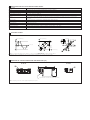
MODE A
When Mode A is active, the driver automatically handles forward/backward
working-cycles with fast-slow speed control according to the programmed
cycle. The digital driver reads the signals from the local proximity microswitches (f1...f4) and from the ON/OFF command signals (start
forward/backward) and consequently activates the various phases
(speed + ramp).
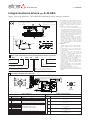
The local proximity microswitches and the command signals are connected to the supply connector (F1...F6, Fig. 1).
The working cycle is thus self generated and actuated by the above
signals, in particular:
• start forward signal (connected to F5) activates the forward movement;
• microswitch signals (f1.... connected to F1....) sequence the forward
cycle phases;
• start backward signal (connected to F6) activates the backward movement.
• microswitch signals (...f4 connected to ...F4) sequence the backward
cycle phases;
Machine
control
unit
Start forward
Start backward
f2
f1
Speed
f3
f4
V1
Forward
R2
R1
V2
R3
Features:
• maximum total four phases selectable (forward plus backward); maximum three phases selectable for each direction;
• for each of the four phases the following parameters can be set (Fig. 2):
- speed regulation Vn: corresponding to the driving current and therefore to the valve opening;
- ramp time Rn: time for a 0÷100% speed step (Vn - Vn-1).
• automatic / on input start: for each direction (forward or backward) it is
possible to choose if the start movement of that direction is activated
automatically at the end of the previous phase or on input (F5 for Start
Forward, F6 for Start Backward);
• polarity: each proximity switch can be set as normally closed / normally
open;
• type: each proximity switch signal can be set as impulsive / continuous;
• diagnostic:
- actual phase, showing the active phase during the cycle;
- actual direction, showing the active direction during the cycle.
• input state, showing F1 ÷ F6 electrical state (ON/OFF)
• configurable direction with positive reference signal (P → A or P → B of
the valve)
f4
f1
Position
f2
f3
R6
R4
V5
R5
V4
Backwards
Fig.1
Speed
Next phase
Previous phase
Phase “n-1”
Phase “n” (n = 1…4)
Position
Fig.2
Activation of “n” phase
7
MODE B
When Mode B is active, the driver actuates up to six different phases
(speed + ramp), according to the configuration of the ON-OFF command signals on the supply connector.
An external PLC may control the desired working cycle by generating the
command signals to the digital driver. Therefore, this Mode of operation is
the same available with the Eurocard analog driver type E-ME-AC-05F/4R-4,
but with the important advantage that digital parameters assure easy,
repetitive and precise settings.
Features:
• maximum six reference signals selectable;
• for each of the six signals the following parameters can be set (Fig. 2):
- speed regulation Vn: corresponding to the driving current and therefore to the valve opening;
- ramp time Rn: time for a 0÷100% speed step (Vn - Vn-1)
• ramp Rstop: ramp time when no imput are selected (actuator stop)
• polarity: each proximity switch can be set as normally closed / normally
opened;
• diagnostic:
- actual phase, showing the active phase during the cycle;
- actual direction, showing the active direction during the cycle
• configurable direction with positive reference signal (P → A or P → B of
the valve)
• the operation processing of the different phases is based on the pin
priority: the phase associated to the pin with higher number is performed before the phases associated to pins with lower number.
Machine
control
unit
Speed
V3
V1
R3
R1
R4
V2
R2
V4
Rstop
R6
Rstop
Position
V5
Fig.1
Speed
Previous phase
Next phase
Phase “n-1”
Phase “n” (n = 1…6)
Position
Fig.2
Activation of “n” phase
G120