1
UPI-41A/41AH/42/42AH USER’S MANUAL
OUTL Pp,A instruction is latched and remains unchanged until it is rewritten. Input data is sampled at
the time the IN, A, Pp instruction is executed. Therefore, input data must be present at the PORT until read
by an INput instruction. PORT 1 and 2 inputs are fully
TTL compatible and outputs will drive one standard
TTL load.
Circuit Configuration
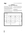
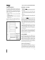
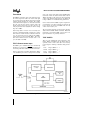
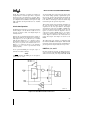
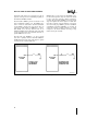
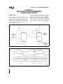
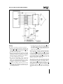
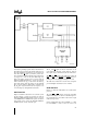
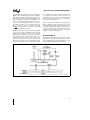
The PORT 1 and 2 lines have a special output structure
(shown in Figure 2-18) that allows each line to serve as
an input, an output, or both, even though outputs are
statically latched.
Each line has a permanent high impedance pull-up (50
KX) which is sufficient to provide source current for a
TTL high level, yet can be pulled low by a standard
TTL gate drive. Whenever a ‘‘1’’ is written to a line, a
low impedance pull-up (250X) is switched in momentarily (500 ns) to provide a fast transition from 0 to 1.
When a ‘‘0’’ is written to the line, a low impedance
pull-down (300X) is active to provide TTL current
sinking capability.
To use a particular PORT pin as an input, a logic ‘‘1’’
must first be written to that pin.
NOTE:
A RESET initializes all PORT pins to the high impedance logic ‘‘1’’ state.
An external TTL device connected to the pin has sufficient current sinking capability to pull-down the pin to
the low state. An IN A, Pp instruction will sample the
status of PORT pin and will input the proper logic
level. With no external input connected, the IN A,Pp
instruction inputs the previous output status.
This structure allows input and output information on
the same pin and also allows any mix of input and
output lines on the same port. However, when inputs
and outputs are mixed on one PORT, a PORT write
will cause the strong internal pull-ups to turn on at all
inputs. If a switch or other low impedance device is
connected to an input, a PORT write (‘‘1’’ to an input)
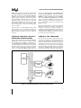
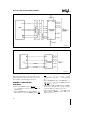
could cause current limits on internal lines to be exceeded. Figure 2-19 illustrates the recommended connection when inputs and outputs are mixed on one
PORT.
The bidirectional port structure in combination with
the UPI-41A/41AH/42/42AH logical AND and OR
instructions provide an efficient means for handling single line inputs and outputs within an 8-bit processor.
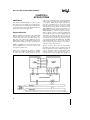
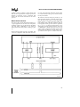
PORTS 4, 5, 6, and 7
By using an 8243 I/O expander, 16 additional I/O lines
can be connected to the UPI-41AH, 42AH and directly
addressed as 4-bit I/O ports using UPI-41AH, 42AH
231318 – 23
Figure 2-18. Quasi-Bidirectional Port Structure
23