1
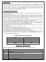
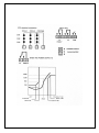
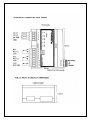
„Power.” Sp.z o.o.
ul.Cienista 15/37
43-100 Tychy , Poland
Tel.: +48 32 7240531
Fax: +48 32 7882271
email: [email protected]
www.powerfullstop.com
USER MANUAL
RELAYS PTC
MODEL:
PWR08
ENGLISH
1) AUXILIARY POWER SUPPLY
AUXILIARY POWER SUPPLY
• Rated voltage 24-240 Vac-dc
• Maximum ratings 20-270 Vac-dc
• Vdc with reversible polarities
INPUTS
• 3 serie of PTC inputs:
- 1 serie for ALL1
- 1 serie far ALL2
- 1 serie far FAN
• removable rear terminals
• input channels protected against
electromagnetic noises and spikes
TESTS AND PERFORMANCES
• assembling in accordance with CE rules
• protection against electrical and magnetic
noises CEI-EN50081-2/50082-2
• dielectric strength 2500 Vac for 1 minute
from relays to sensors, relays to power
supply, power supply to
sensors
• ambient operating temperature —20°C to
+60°C
• humidity 90% no-condensing
• ABS self-extinguishing housing — NORYL
94VO
• Opt. Protection treatment of electronic part
• Frontal in polycarbonate - IP54
• Burden 2 VA
• Data storage 10 years minimum
• SeIf-diagnostic circuit
OUTPUT
• 2 alarm relays (ALL1-ALL2)
• 1 alarm relay for fan control (FAN)
with time delay off (5-10-20-40
min)
• output contacts capacity: 5A250Vac res.
DISPLAYING AND DATA
MANAGEMEPIT
• Led indicating alarm. Trip channel
or fan
• Led indicating fault
• 2 alarm thresholds
• 1 alarm ON threshold for fan
control
• entering the programming by
frontal push button
• automatic output from
programming cycle after 1 minute
of no-operation
DIMENSIONS PWRO8
• 90 x 105 mm DIN 43700 prof. 75 mm
The PWR08 is the most advanced unit on the market as regards temperature
monitoring units for MT cast resin transformers, which utilize PTC sensors. The unit
gives the ALL1 pre-alarm arid TRIP signals when the temperature Iimits pointed out
by the PTC of the windings are reached. The PWR08 is arranged to control the
cooling ventilation of the transformer. The unit controls continuously the efficiency
of PTC sensors and when one of these is detective. you have immediately a signal
of detective sensor. The FAN relay is energized until temperature is superior than
δNAT value; when the temperature gets down under this value the relay is still
energized for the established ventilation time (5-10-20-40’ delay function)
As the PTC actually produced by all the European manufacturers have different
specifications among the Power is not answerable for wrong functioning of the
control system, caused by PTC with different resistance values, from those
indicated in TAB.1
2) USE AND PROGRAMMING
A) PWR08: FAN programming cycle
B) PWR08: Alarm relay test
C) PWR08: FAULT PTC sensor
D) PWR08: diagnostic device for PTC
ITEM “A”
NOTE: PB.=push button / MOM=momentary / CONT.=continuously
POS.
ACTIONS
RESULTS
1
give voltage to the unit
the GREEN led lights
push mom. the P.B. L.TEST two times the red led PRG/T.FAN light
2
flashing
within 5‖ push the P.B. until the led
the led PRG/L.TEST is lighted
3
PRG/L.TEST is lighted fixed
fixed
push mom. the P.B. L.TEST
the red led switches from T1÷T4
4
(FAN time 5’÷40’)
stop the push the P.B. when the led
5
is ON, the Tx corresponds to the
requested time
6
end of FAN cycle programming
all the leds are switched 0FF
IF YOU DO NOT NEED ANY FAN CYCLE
When you are at the point 4, you have one passage without any led lighted ON.
The unit is programmed only for L1 and L2 ( alarm and disconnecting)
ITEM “B”
1 push the P.B. mom. three time in
sequence
2 within 5‖ push cont. the P.B. until the
leds are lighting all together
3 after 5‖ the relay FAN is ON then L1/L2
are ON
4 end of ―TEST CYCLE‖
ITEM “C”
1 One of the PTC is in Short Circuit
2
Replace or repair the PTC
the leds T1,2,3,4 are lighting in
sequence
the leds T1,2,3,4 are lighting all
together
leds and relay of FAN-L1-L2 are ON
all the red leds are light 0FF
The red led FLT and the
corresponding led (L1-L2-L3-L4)
are flashing
The leds are light OFF
ATTENTION:
if you PWRO8 has not the right PTC model connected, the leds lighten the PTC
temperature at delta NAT+T=1300ohm.
COOLING FAN CYCLE “DELAY ON”
the PTC/FAN is ON
the FAN relay is ON and the red led
is switched ON
the temperature decreases under the
the FAN relay remains ON for the
PTC value
fixed time and the red led flashing
until the end of the selected time
if the temp. raises again over the PTC
the ed stops to flash and remains
val.
fixed
ITEM “D”
The PWR08 is provided, in the standard version, with the option diagnostic device
for PTC connected.
This software device could be connected or not with the following easy procedure:
to disconnect the diagnostic device for PTC give power supply to the unit pushing
the L/TEST button and keep it pushed till the YELLOW FAULT LED is ON.
to connect the diagnostic device for PTC give power supply to the unit pushing the
L/TEST button and keep it pushed till ALL THE LED are 0FF.
3) ALARM 1 RELAY FUNCTIONING
The ALL1 relay operates when the unit is powered with the N.O. contact OFF.
The relay de-energizes and the contact is OFF when there is an alarm of the L1 PTC
or when the unit is damaged. The ALL1 relay has the function of the PTC sensor
FAULT.
If this relay operates during the lighting of the frontal FAULT LED, it means that
there is an error in the reading or the PTC sensor.
It is possible to find it, thanks to a second lighting which corresponds to the FAULT
channel.
4) ALARM RELAY 2 ( TRIP)
The ALL2 relay operates when there is an alarm on the L2 PTC.
5) FAN RELAY
During the programming, it is possible to plan the cooling time or to take the FAN
option OFF.
If the FAN is OFF, the relay doesn’t operate. for this reason the respective PTC can
be left out. If the FAN is ON, the relay operates from the first signalling of the
respective PTC and the FAN led is ON. The relay is ON during all the time in which
the PTC indicates the threshold overcoming. When the PTC checks the normal
temperature, the PWR08 unit keep the relay ON for all the time signed during the
programming and the FAN led lightens.
When the time is expired, with a normal temperature, the relay doesn’t operate
anymore and the LED switches OFF.
6) DIAGNOSTIC DEFECTIVE PTC SENSORS
If one a the PTC is in short circuit or it is interrupted you have the following
signaling:
PTC alarm ALL1 Fault led + ALL1 flashing
PTC trip
ALL2 Fault led + ALL2 flashing
PTC fan
FAN Fault led + Fan
The trouble is not signalled, if one of PTC serie is interrupted when its total
resistance are already TRIP threshold.
7) WARRANTY
The ―PWR‖ units under warranty for 24 months from the delivery date signed on
the unit.
The warranty is recognized when the unit breaks down due to some production
faults or insufficient calibration, the warranty is not valid when tampered with or
when it has been damaged for a wrong sensor connection or wrong power supply,
out of the max working Iimits (20-270 Vac-dc). The warranty is not valid when the
unit has been fuIminated by excessive transitory voltage. In this case Power is not
answerable for damages caused by faulted or defective unit. All the delivery
expenses (there and back) of the unit must paid by the Customer. (ANIMA prices
Col.C).
PS: In order to verity the functioning of the unit we suggest the use of our
simulator mod. SIM-PTC.
8) IMPORTANT NOTICE
Before making the insulation test on the electrical panel on which the unit is
installed, you must take it off from the power supply line, in order to keep it out of
damage.
9) TEMPERATURE SENSOR “PTC”
We can compare the PTC to the electronic bimetallic thermoswitch, which contacts
close or open in a range of temperature, that is their work characteristics (
δNAT=working temperature). The thermostat is set only for one working temp,
which can change from 60 up to 180, with increasing steps of 10°C (60-70-80-90100-110-120-130-140-145-155-160-170-180). The bimetallic thermoswitch has
the electric contact that opens or closes at different temperatures, always around at
± of the working temperature (δNAT). The difference between the opening and the
closing temp. Represents the working differential of the thermostat (ΔT°). Highly
accurate and expensive bimetallic thermoswitch are able to control the temp.
between ± 1°C of δNAT. The common bimetallic thermostat has control accuracy,
that is 3 ÷ 5 °C. The PTC are electronic temp. Sensors, which change their electric
resistance depending on the temp. Picked up. The δNAT does exist, as for the
bimetallic thermostat, so for the PTC. The PTC do not allow an accurate temp.
Control, because their ohmmic characteristical values are fixed to -5°K to +5°K of
δNAT. The characteristical resistance values of the PTC are defined by the Norme
DIN 44081/44082. Being very steep the PTC curve, in the out line included between
δNAT -5° and δNAT +5°, makes the control in a temp. Range lower than ± 5°K
very difficult. If they are used in alarm system, obviously the PTC do not assure
high accuracy.
10) TECHNICAL SPECIFICATION FOR “PTC”
TEMPERATURE
From -20 to δNAT -20°K
At δNAT -5°K
At δNAT +5°K
At δNAT +15°K
Electrical insulation
Maximum working voltage
RESISTANCE Ω
From 20 to 250
≤550
≥1330
≥4000
VOLTAGE TEST VCC
≤2.5
≤2.5
≤2.5
≤7.5 impulse voltage
2500 Vca
30
11) PTC RESISTANCE VALUES ACCEPTED TO CONWECT THE PWR0B (TAB.1)
FUNCTION
RESISTANCE Ω FOR SINGLE PTC OR MULTIPLE IN
SERIE
NO ALARM
Temperature of the
machine under the
alarm set
ALARM
Alarm set reached for
FAN-ALL-TRIP
FOC
Sensor circuit = Open
Circuit
FCC
Sensor circuit = Short
Circuit
HIGHER THAN 50Ω
HIGHER THAN 1800Ω
HIGHER THAN 200KΩ
With fast increase ≤ 3‖
LOWER THAN 15Ω
12) SIM.PTC ELECTRQNIC SIMULATOR FOR PTC FOR MONITORING UNITS
MOD. PWR08
This simple and economic PTC simulator, has been realized for testing the
functioning of the temp.electronics units Mod.PWRO8. The external switches insert,
step by step, different resistance values that are in accordance with the working
program of the unit. This makes possible to simulate the complete functioning of
the unit as well as to verify the PTC diagnosis circuit. The PWR08 has been
engineered to make simple and uncostly the thermic control or electric units such
as soon as the transformer reaches the temp. Values equal to the PTC δNAT, fixed
into the transformer windings. The PWR08 further provides to drive the fan cooling
system, when it is equipped with the suitable PTC serie. It is also widly used for
electric motors temp. Protection.
Unique in its kind the PWR08 makes the PTC status diagnostic. This detail gives to
the unit, and than to the control system, a very high safety factor. To obtain all
this, Power engineering staff made a wide research and a deep study of the PTC
produced in Europe. On the base of these studies, it has been fixed a PWR08
working program that allows the unit to work with almost all the PTC produced by
European manufacturers.
13) HOW TO USE
Connect the multiple plug to the sensors input of the PWR08. Set the three
switches on the NOR position.
In case the unit is NOR programmed for FAN Control, operate only with L1 and L2
switches.
14) ALARM TEST(L1 & L2)
Set the switches L1 and L2 on the TRIP position. On the PWR08, the L1 and L2 Ieds
light ON, and the corresponding relay switches ON.
15) FAN TEST
Set the switches FAN on the position TRIP. The FAN led on the PWR08 will Iight
fixed. The FAN relay switches ON. Fix the FAN switches on the NOR position; the
FAN led starts to flash for a time corresponding to the programmed one (FAN
CYCLE). At the end of the programmed FAN time, the FAN led stops to flash and
goes OFF; the FAN relay returns to N.O. position.
16) SENSORS DIAGNOSTIC
The PTC sensors have two possible failures: one open circuit (Foc) and the other is
short circuit (Fcc).
On the simulator there are two Foc conditions: the first Is referred to the resistance
value higher than 200 KΩ that simulates The PTC resistance value at δNAT +
30/40°C. We match this condition on the PTC FAN when, being running the cooling
fans, the trans former continues to increase its temp.
In this condition the temp, Monitoring unit does not give alarm, neither stops the
ventilation. The same working philosophy is applied to L1 and L2 PTC.
The Foc2 position simulates the PTC circuit undoubtedly open. In order, to simulate
the PTC open circuit and to verify the corresponding indication on the PWR08, you
must move rapidly the switch from the position NOR to Foc2.
The PWR08 will show with flashing led. which of the three PTC (or serie) is
definitely open.
In this case the L1 relay shall switch in pos. 6-7.
It Is useful to repeat what we already mentioned in the instruction manual, that’s
to say that when a PTC reaches and overcomes the δNAT.
If it happens a Foc/Fcc condition the Fault will be not displayed.
This auto-diagnosis program performance allows to give the display priority to the
ALARM and FAN functions. If, during the simulation. the PWR08 does not react in a
proper way please contact Power.
RESISTANCE VALUES OF SIM-PTC
FUNCTION
TRIP
NOR
FCC
FCO 1
FCO 2
RESISTANCE VALUES [Ω]
2,0 K
220
4,8
500 K
∞
PWR08 TEST DESCRIPTION
The unit was submitted to the following tests during the production :
Number
1
2
3
4
5
6
7
8
DESCRIPTION
PC board test
Input test
Test of relay contacts and outputs
Key test
Lamp test
Calibration at 100 and 200° (for temperature monitoring units)
Software test
Burn – in minimum 24 H.