1
Hardware Installation Guide
Axess-Ready
Surge Protector/Power Conditioner
SA-82-AR / XF2-AR
SOFTWARE VERSION: 1.01.41
FIRMWARE VERSION: 1.01.06
SurgeX • 517 North Industrial Drive, Zebulon, NC 27597
Customer Service: 800-645-9721 • Technical Support: 800-645-9721 • Fax: 919-269-0454 • www.surgex.com
Table of Contents
I.
INTRODUCTION
2
II.
INSTALLATION
3
ETHERNET CONNECTION
AC POWER CONNECTIONS
LED INDICATORS
III.
INITIAL SETUP
DEVICE MANAGEMENT UTILITY (DMU)
SETTING THE IP ADDRESS
3
3
3
4
4
6
IV.
OUTLET ON LED INDICATOR
7
V.
WEB SERVER
8
PASSWORD
CONTROL AND STATUS PAGE
SETUP PAGES
DEVICE
NETWORK
AUTOPING
SCHEDULE
PASSWORD
VI.
COMMAND LINE INTERFACE (CLI) PROTOCOL
PROMPTS
CONTROL COMMANDS
DEVICE COMMANDS
NETWORK COMMANDS
AUTOPING COMMANDS
USER COMMANDS
EVENT COMMANDS
VII.
DxP PROTOCOL
8
8
9
9
10
11
13
14
15
15
15
15
16
17
17
18
19
OVERVIEW
HELLO HANDSHAKE
DXP PACKET
COMMANDS
DESCRIPTORS
PAYLOADS
19
19
20
21
21
23
FIRMWARE UPGRADES
24
IX.
RESET BUTTON
24
X.
SPECIFICATIONS
25
VIII.
SA-82-AR / XF2-AR User Manual
Page 1
I.
Introduction
The SurgeX® SA-82-AR/XF2-AR is a network attached, IP addressed, web controlled AC surge
protector and power conditioner. The SA-82-AR/XF2-AR may be used to switch up to 8A at
120V. The simple web server structure allows basic control of two outlets. The extensive
programming and setup capabilities are accessed by a web browser, through a Device
Management Utility (DMU), or through a Command Line Interface (CLI).
•
The SA-82-AR/XF2-AR features SurgeX® Series Mode surge protection, Impedance
Tolerant EMI/RFI filtering and Over-Voltage Shutdown.
•
Remote reboot any device: monitors, routers, servers, kiosks, etc. The remote device
need not be network attached.
•
Conserve energy by powering down equipment when not in use.
•
Telnet access uses the Command Line Interface (CLI) structure and syntax to
completely configure and control the SA-82-AR/XF2-AR. This Axess Ready (AR) device
also supports the DxP protocol, which allows software developers to integrate the unit
into custom applications.
•
Up to 2 systems can be continuously monitored with AutoPing, with automatic power
control upon loss of contact. Reboot crashed systems, or provide auto power-up or down for environmental controls and notification systems.
•
The SA-82-AR/XF2-AR utilizes 2 levels of password security, with only the
administrative account having access to setup and configuration.
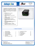
Located on the rear panel are the input IEC power plug, network connection (RJ-45), 8A circuit
breaker, and output receptacles.
The front panel contains the Outlet On LED, Self-Test LED, System On LED, and Reset button.
SA-82-AR / XF2-AR User Manual
Page 2
II. Installation
Ethernet Connection
The RJ45 connector for 10/100 Ethernet is situated on the rear
panel beside the input power plug. The default IP Address is
192.168.1.254.
AC Power Connections
Connect the device to be powered On and Off to the output
duplex receptacle.
Ensure that the total combined load of all controlled devices does
not exceed 8 Amps.
Connect one end of the supplied power cord to the connector
labeled “AC Input”, and the other end to a properly grounded AC
outlet.
LED Indicators
The green Self-Test LED indicates that the internal surge protection circuitry is fully functional.
The red Outlet On LED indicates that power is being supplied to the two receptacles.
The red System On LED indicates that the Axess system is On. This indicator will turn off if the
AC voltage rises above 145V, and AC power will be removed from the output receptacles in
order to protect connected equipment. When the AC voltage returns to below 135V, power will
automatically be restored to the output receptacles and the System On LED will turn on.
SA-82-AR / XF2-AR User Manual
Page 3
III. Initial Set-Up
Device Management Utility (DMU)
The SurgeX Device Management Utility (DMU)
provides the easiest means to find and configure
your AR for use. The DMU can:
1. Automatically discover multiple ARs on a
local network.
2. Display the current IP address of each AR.
3. Allow the setting of a new IP address for each AR.
4. Perform firmware upgrades.
5. Return an AR to Factory Defaults.
The SurgeX Device Management Utility is available
on the AR CD or on the SurgeX website at
http://www.surgex.com
Note: The IP address can only be set within the first
2 minutes after powering up the AR. The utility will
only work with ARs on the same local subnet as the
PC.
Device
Discover: Automatically discover all ARs on the local network. The DMU will display
the location name of the AR, the product
ID and version number, the current IP
address, and the MAC address. Factory
defaulted ARs will display with the name
New SX-iPD and have either the factory
default IP address of 192.168.1.254 or an
IP address that was automatically
assigned by the DHCP server on your
network. If the IP address was assigned
by a DHCP server, no changes to the IP
address are required.
The IP address field also indicates the port for web access that is currently in
use by the AR. The standard port for web browser accessibility is factory
default Port 80.
Add: Manually add an AR by IP address.
Clear: Clear the list.
SA-82-AR / XF2-AR User Manual
Page 4
III. Initial Set-Up (continued)
Manage
Open Browser: Opens the web browser interface for the selected AR.
Upgrade Firmware: Starts the Firmware Upgrade dialogue.
Firmware Upgrade requirements:
Valid firmware file.
Administrative login credentials.
“Upgrade Enable” must be set to yes, set via web page or CLI.
Set
IP Address: Changes the IP address of the selected AR.
Factory Defaults: Return the selected AR to a Factory Default state. This action
must be performed within the first 2 minutes after powering up the unit.
Local Address: Select the IP address to Discover on. This may be necessary for
computers with multiple network connections.
Exit
Exits the DMU program.
Help
Online Help: Opens a web browser to online help resources.
About: Displays DMU version information.
SA-82-AR / XF2-AR User Manual
Page 5
III. Initial Set-Up (continued)
Setting the IP Address
ARs are configured with a factory default IP address of 192.168.1.254.
To set the AR’s IP address using one of the following methods, the computer and AR must be
on the same local network.
DMU: Follow the steps in the preceding subsection to set the IP address using the
Device Management Utility (DMU).
CLI: These are the basic commands to set the network parameters. After setting these
parameters, the AR will need to be rebooted for the settings to take effect. Any
command that requires rebooting of the AR will provide a prompt to do so. All commands
may be entered as required before rebooting. Manually specifying the IP address via CLI
automatically sets the address as static.
Example: Telnet to default IP address of 192.168.1.254 on default Port 23:
SurgeX Axess Ready v1.01.41
User> admin
Password> *****
Axess Ready> set ipaddress 10.1.2.69
Ok
Axess Ready Reboot Required> set subnet 255.255.255.0
Ok
Axess Ready Reboot Required> set gateway 10.1.2.1
Ok
Axess Ready Reboot Required> reboot
The CLI command set ipmode dhcp followed by a reboot command may be used to
configure the AR to automatically acquire its network settings from a DHCP server. A
DHCP server will automatically assign an IP address (dynamic address), as well as the
Subnet Mask and Gateway.
To determine what IP address has been automatically assigned by the DHCP server,
you will need to use the Discover feature of the DMU or query your DHCP server and
locate the MAC address of the AR in the DHCP server’s IP/MAC table.
Web: To set the IP address using a web browser, navigate to the current IP address of
the AR (192.168.1.254 if the unit is in a factory default state). Enter the administrator
credentials (Factory Default User: admin, Password: admin), click on “Setup”, then click
on “Network” and follow the directions in the Web Server/Network/Setup section of this
manual.
SA-82-AR / XF2-AR User Manual
Page 6
IV. Outlet On LED Indicator
The Outlet On LED functionality is as follows:
LED State
On (Solid)
On (Blinking)
Off
Description
The outlets are On.
The Reset button has been pressed for 5 or more seconds. Releasing the
button will restore the AR to a factory default state.
The outlets are Off.
SA-82-AR / XF2-AR User Manual
Page 7
V. Web Server
The Axess Ready web interface provides the easiest means of operating the outlet and
changing configuration parameters.
To access the web interface, open a web browser and enter the IP address of the AR into the
address bar. The factory default IP address is 192.168.1.254.
Password
The AR uses two username/password credential sets, one for normal power control (user) and
one that also provides access to the Setup functions (admin).
Default credentials:
Role
Username (fixed)
Administrator
admin
User
user
Password (user set)
admin
user
Enter a valid username and password when prompted. When
the proper username/password combination is received, the
Control and Status Page is displayed.
Control and Status Page
Once a user is validated, the Control and Status page is
displayed.
Note: Only one user may be logged in to the AR at a
time.
Press “Power On” or “Power Off” to turn the AC output
On or Off. In the event of a power outage, the AC output
will return to its last known state prior to the outage.
Press “Cycle Power” to temporarily change the state of
the AC output for a specified cycle time (factory default is 10 seconds). The cycle operation
performed will either be On-Off-On or Off-On-Off, depending on the initial state of the AC output.
During the power cycle operation, the Power Status bar will indicate the temporary status with a
Blue background. Once the cycle is complete, the status bar will revert to its original condition.
To abort a power cycle, press either “Power On” or “Power Off” and the outlets will assume that
status.
If the AutoPing feature is in use, this page will also display the current status (OK or Failed) for
each AutoPing, a counter of how many times the ping failed, and a counter of how many times
the defined action was triggered. Reset buttons for the Fail and Trigger counters are available
for the admin login.
Use the Refresh button to update the page with the most current status. Use of the browser’s
refresh button may lead to inadvertent power switching. If an NTP time server is being used, the
time of the last refresh will be displayed in the upper right corner.
SA-82-AR / XF2-AR User Manual
Page 8
V. Web Server (Continued)
Setup Pages
Setup pages are only available while logged in with Administrator credentials. Press Save to
save the new settings. If the new settings require the AR to be rebooted, a Reboot button will
appear at the bottom of the page. Settings requiring reboot will not take effect until the unit is
rebooted.
Device
•
Location ID: Specifies a name label (up to 20 characters) that will be displayed at
the top of all pages. Assigning unique names is helpful for management of multiple
units.
•
Cycle Time: Specifies the length in seconds of a power cycle (1-999 seconds). This
is the amount of time the outlet will temporarily be On or Off, depending on the initial
outlet state.
•
Upgrade Enable: Enables the ability to upgrade the firmware of the AR.
•
Auto Logout: Specifies the inactivity timer duration in minutes (0-99 minutes). If
there is no activity after the specified amount of time, the user will be automatically
logged out. Setting the timer duration to 0 disables the timeout feature.
Important: As the AR allows only one web user logged in at any time, use
caution when disabling the timeout feature, as it is possible to lock out other
users by forgetting to log out. Closing the web browser will not log the user
out, and will lock out web access. In this situation it will be necessary to
access the AR via telnet and reboot the unit.
SA-82-AR / XF2-AR User Manual
Page 9
V. Web Server (Continued)
Network
•
IP Mode: Select Static to manually set the IP address using the fields below, or
choose DHCP to allow the AR to automatically acquire its network settings from a
DHCP server.
•
IP Address: Enter a static IP address in dotted decimal format. This field will be
automatically set if using DHCP.
•
Subnet Mask: Enter the Subnet Mask in dotted decimal format. This field will be
automatically set if using DHCP.
•
Gateway:
Enter the Gateway in dotted decimal format. This field will be
automatically set if using DHCP.
•
HTTP Port: Specify the port the web server will be accessed on. If the port is
changed from the default value of 80, the AR may be accessed by specifying the
new port number in this format: http://IPADDRESS:NEWPORT. Example: Navigate
to http://192.168.1.254:8000 for an IP address of 192.168.1.254 on port 8000.
•
Telnet Port: Specify the port to use for telnet access (default 23).
•
DxP Port: Specify the port to use for DxP protocol (default 9100).
SA-82-AR / XF2-AR User Manual
Page 10
V. Web Server (Continued)
AutoPing
The AutoPing feature allows the AR to automatically detect failed equipment and perform a
timed reboot or other power control function (like turning on an indicator or siren). First specify
one or two IP addresses to be periodically pinged. When the AR no longer receives a response
from these addresses, the programmed power control function is actuated. AND or OR logic can
be applied to the two addresses, so that both (AND) or either (OR) must fail in order to trigger
the selected action.
Examples:
Server monitor: AR is installed with
the device it monitors and
automatically reboots if there is no
response. Ideal for Kiosks and
Servers.
Service monitor: AR is installed with
the device to be rebooted, but pings a
remote host to test the communication
channel. Ideal for DSL/Cable Modem
verification.
AR monitors a network device, and
powers up an alarm or redundant
system when there is no response.
Ideal for Hot Standby Servers,
Environmental Control, Alert for any
network failure.
•
IP Address 1 and 2: Enter the IP address(es) of the device(s) to be pinged.
•
Frequency 1 and 2: Enter the desired ping frequency in seconds for the
device(s) to be pinged (1-999 seconds).
•
Fail Count 1 and 2: Enter the number of times the ping must consecutively fail
(1-999) before the selected action is triggered.
•
Mode: Select the logic to be used (AND, OR, or Single). With AND logic, both
AutoPings must exceed their fail count to trigger the action. With OR logic, the
action will be triggered if either AutoPing exceeds its fail count. With Single, only
AutoPing 1 is used.
SA-82-AR / XF2-AR User Manual
Page 11
V. Web Server (Continued)
•
Action: Select the action to be triggered.
None
Power On – Latch
Power On – Follow
Power Off – Latch
Power Off – Follow
Power Cycle
Power Cycle - Once
AutoPing not used
Upon triggering, AR will power on and remain so until
changed via web, telnet, or DxP.
Upon triggering, AR will power on. When the ping
response returns, AR will power off.
Upon triggering, AR will power off and remain so until
changed via web, telnet, or DxP.
Upon triggering, AR will power off. When the ping
response returns, AR will power on.
Upon triggering, AR will cycle the power. AR will then
wait for (Ping Frequency x Fail Count) seconds; if the
response does not return, the power will be cycled
again. This will repeatedly continue until the ping
response returns or AutoPing is turned off. Ensure that
the AutoPing frequency is longer than the time
required to reboot the device.
Upon triggering, AR will cycle power one time. It will
not cycle again automatically until the ping response
returns and is lost again.
SA-82-AR / XF2-AR User Manual
Page 12
V. Web Server (Continued)
Schedule
The AR can schedule up to 8 recurring power events. For each event, you may define the
starting date and time, the action to be taken, and the repetition interval (optional).
Important: A Network Time Server (NTS) must be specified and enabled in order to use the
time scheduling feature. A list of public time servers is available at http://www.ntp.org.
•
Enable: Checking the Enable box enables the time scheduling feature.
•
Time Server: Enter the IP address of the Network Time Server to be used.
•
Time Zone: Specifies the local time zone relative to GMT. For example, the setting
for EST is -5.
•
Date: Set the initial date for the event in mm/dd/yyyy format.
•
Time: Set the initial time for the event in hh:mm:ss format. Hours are specified in 24
hour format; for example, 8:05:00 pm would be entered as 20:05:00.
•
Repeat (Optional): Set the repetition interval. 0-999 Days, Hours, or Minutes.
•
Action: Set the action to be scheduled. On, Off, or Cycle.
•
Clear: Deletes a schedule.
SA-82-AR / XF2-AR User Manual
Page 13
V. Web Server (Continued)
Passwords
Two passwords are used by the AR. The User password allows control of the AC
receptacle state, but provides no access to Setup functions. The Administrator password
allows full control and setup of the AR.
Passwords may be up to 20 characters long, and are case sensitive.
•
Old Password: Enter the password currently in use.
•
New Password: Enter the new password to be used.
•
Confirm Password: Enter the new password to be used again.
Default credentials:
Role
Administrator
User
Username (fixed)
admin
user
SA-82-AR / XF2-AR User Manual
Password (user set)
admin
user
Page 14
VI.
Command Line Interface (CLI) Protocol
The Command Line Interface provides complete setup of all functions of the AR. The CLI may be accessed through the Telnet
protocol, and requires a Telnet client program. Some commands of the CLI require administrative rights; these are indicated in the
following tables.
Prompts
Prompt
Description
User>
Prompts the user to enter the user name (either user or admin).
Password>
Prompts the user to enter the password.
SX-iPD>
Prompt displayed while logged in.
SX-iPD Reboot Required>
Prompt displayed after changes have been made that require a reboot. This prompt
will remain active until the AR has been rebooted.
Control Commands
Command
Description
Admin
get outlet
Returns the current status of the outlet.
No
set outlet < on | off | cycle >
Sets the outlet to the selected state.
No
Device Commands
Command
Fact Def
Description
Admin
Fact Def
get location
Returns the location ID.
Yes
New SA-82AE
set location < 20 character max >
Sets the location ID.
Yes
get cycle
Returns the cycle time currently in use in seconds.
Yes
set cycle < 1-999 >
Sets the cycle time in seconds.
Yes
get upgrade enable
Returns the upgrade enable status.
No
set upgrade enable < yes | no >
Enables or disables the ability to upload new firmware.
Yes
logout
Terminates the telnet session.
No
reboot
Reboots the AR.
Yes
SA-82-AR / XF2-AR User Manual
10
Disabled
Page 15
VI.
Command Line Interface (CLI) Protocol (continued)
Network Commands
Command
get network
Description
Returns all network settings currently in use. Example:
Mode:
IP Address:
Subnet:
Gateway:
HTTP Port:
Telnet Port:
DxP Port:
Timeout:
Ok
Admin
Yes
Fact Def
DHCP
10.1.2.69
255.255.255.0
10.1.2.1
80
23
9100
20
set ipmode < static | dhcp >
Sets the IP address mode. Static mode locks the IP
address as set; DHCP mode allows a DHCP server
to assign the address.
Yes
Static
set ipaddress < dotted decimal >
Sets the IP address.
Yes
192.168.1.254
set subnet < dotted decimal >
Sets the Subnet Mask.
Yes
255.255.255.0
set gateway < dotted decimal >
Sets the Gateway address.
Yes
192.168.1.1
set http port < 0-65535 >
Sets the port that the internal Web server listens for
incoming connections on. When set to 0 the web
server is disabled. May not be disabled when Telnet
and DxP are both disabled.
Yes
80
set telnet port < 0-65535 >
Sets the port that the internal Telnet server listens for
incoming connections on. When set to 0 the Telnet
server is disabled. May not be disabled when Web
and DxP are both disabled.
Yes
23
set dxp port < 0-65535 >
Sets the port that the internal DxP service listens for
incoming connections on. When set to 0 the DxP
service is disabled. May not be disabled when Web
and Telnet are both disabled.
Yes
9100
set timeout < 0-999 >
Sets the automatic network timeout in minutes.
Yes
2
SA-82-AR / XF2-AR User Manual
Page 16
VI.
Command Line Interface (CLI) Protocol (continued)
AutoPing Commands
Command
get autoping
Description
Returns all AutoPing settings currently in use.
Example:
Admin
Yes
Fact Def
AutoPing 1
AutoPing 2
IP Address:
10.1.2.36
0.0.0.0
Frequency:
60
10
Fail Count:
3
3
Status:
OK
OK
Trigger Count: 0
0
-------------------------------------Mode:
Single
Action:
On-Latch
Ok
set autoping < 1 | 2 > ipaddress < dotted decimal >
Sets the IP address to be pinged for AutoPing 1 or
2.
Yes
0.0.0.0
set autoping < 1 | 2 > frequency < 1-999 >
Sets the frequency (how often the ping is sent) for
AutoPing 1 or 2 in seconds.
Yes
10
set autoping < 1 | 2 > failcount < 1-999 >
Sets the number of consecutive failures the
AutoPings must detect before the AutoPing
considers the pinged device to be failed.
Yes
3
set autoping mode < single | and | or >
Sets single AutoPing (AutoPing 1) or two AutoPing
relationship AND or OR.
Yes
AND
set autoping action < none | on-latch | on-follow | offlatch | off-follow | cycle | cycle-once >
Sets the action to be performed when the AutoPing
is triggered.
Yes
None
Admin
Yes
Fact Def
user | admin
User Commands
Command
set password < user | admin > < old > < new > < repeat >
SA-82-AR / XF2-AR User Manual
Description
Sets the password of the User or
Administrator.
Page 17
VI.
Command Line Interface (CLI) Protocol (continued)
Event Commands
Command
Description
get events
Returns all scheduled events currently in use. Example:
Date
Admin
Time Repeats
Fact Def
No
Action
1. 12/22/2011 14:00 every 2 Hour(s) Cycle
2.
every 0 Day(s)
On
3.
every 0 Day(s)
On
4.
every 0 Day(s)
On
5.
every 0 Day(s)
On
6.
every 0 Day(s)
On
7.
every 0 Day(s)
On
8.
every 0 Day(s)
On
Ok
get time
Returns the current time and time server. Example:
No
Current Time: 10:14:17 12/20/2011
Server:
10.1.2.12
Ok
set time server < dotted decimal >
Sets the IP address of a Network Time Server.
Yes
64.90.182.5
5
set time enable < yes | no >
Enables or disables the use of a time server and scheduled
events.
Yes
No
set event < 1-8 > date < mm/dd/yyyy >
Sets the scheduled event’s starting date.
Yes
set event < 1-8 > time < hh:mm:ss >
Sets the time the scheduled event will occur in 24 hour format.
Yes
set event < 1-8 > repeat < day | hour |
minute >
Sets the repetition interval type for the selected event.
Yes
set event < 1-8 > mult < 0-999 >
Sets the number of repetition intervals for the selected event.
For example, 20 days, 30 minutes, 24 hours, etc.
Yes
set event < 1-8 > action < on | off | cycle >
Sets the action to be performed at the scheduled time.
Yes
del event < 1-8 >
Deletes the scheduled event.
Yes
SA-82-AR / XF2-AR User Manual
Page 18
VII.
DxP Protocol
Overview
The DxP Protocol is a packet-based protocol designed to be extensible. This protocol is
transmitted over TCP on a user-defined port. The factory default DxP port is 9100.
The protocol uses a Hello handshake to establish unique sequence numbers to allow for
advanced security when AES encryption is used. With AES enabled, all messages must be
encrypted with the AES Passphrase set in the device.
After the Hello, a Command and Response sequence follows. Any number of
Command → Response sequences are permitted after Hello.
Hello Handshake
The client sends a Hello message in the form of a text string ‘hello-000’. The DxP enabled
device will respond with a packet containing the unsigned 16 bit sequence number. This
sequence number is incremented by the client and server with each correct packet sent.
Example:
Client
hello-000
Command
(seq 1235)
Command
(seq 1237)
→
←
→
Server
1234
(seq 1234)
←
→
Response
←
Response
SA-82-AR / XF2-AR User Manual
Page 19
VII.
DxP Protocol (Continued)
DxP Packet
The packet is broken up into 2 parts: the Header and the Payload.
Header
The header is used to carry general information, such as is shown in the C programming
structure below:
typedef struct {
eCmnd command;
char[21] uName;
char[21] password;
uChar desc;
uChar param;
uint16 seq;
} THeader
Variable
command
uName
password
desc
param
seq
Description
Enumerated type that tells the DxP server what class of command is being
sent. See the Commands subsection for a full list of command classes.
Reserved for future use. It will contain the user name of a user on the ipIO that
is being accessed.
Reserved for future use. It will contain the password of the user above.
Command descriptor that describes the individual command within a command
class. By extension it lets the server know what the payload is. There is a
different set of descriptors for each command class; see the Descriptors
subsection for a full list of descriptors by command class.
Reserved for future use. Optional parameter that may be passed to the server
in addition to the descriptor.
The packet’s sequence number. Used as part of the security scheme.
Payload
The payload is determined by a combination of the command class and the descriptor. The
payloads are described with the descriptor; see the Descriptors subsection for details.
SA-82-AR / XF2-AR User Manual
Page 20
VII.
DxP Protocol (Continued)
Commands
There are currently 7 command classes. All classes are defined in the C programming
enumerated type definition below:
typedef enum {
eCmnd_null,
eCmnd_set,
eCmnd_get,
eCmnd_io,
eCmnd_keepAlive,
eCmnd_rss,
eCmnd_rcu
} eCmnd;
0
1
Command
eCmnd_null
eCmnd_set
2
eCmnd_get
3
4
eCmnd_io
eCmnd_keepAlive
5
eCmnd_rss
6
eCmnd_rcu
Description
This is a null command and should not be sent to the server.
This command is used to set programmable variables on the
server.
This command is used to get programmable variables from the
server.
This command is used to monitor and control the I/O on the server.
This command is sent to the server as a means of allowing the
client to validate the communications path to the server.
This command class is used to control the RSS nest using the
RCU.
Note: Project specific command. Not for general use.
This command class is used to update the display of the RCU.
Note: Project specific command. Not for general use.
Descriptors
Descriptors are used to describe the individual command within a command class, and the
payload that the packet contains. All of the descriptors and their payloads are outlined by
command class below.
eCmnd_set
The descriptors for this command class will be product specific.
eCmnd_get
The descriptors for this command class will be product specific.
SA-82-AR / XF2-AR User Manual
Page 21
VII.
DxP Protocol (Continued)
eCmnd_io
typedef enum{
eIO_null,
eIO_changeRelay,
eIO_changeRelays,
eIO_getRelay,
eIO_getRelays,
eIO_getInput,
eIO_getInputs,
eIO_pulseRelay,
} eIO;
Command
eIO_changeRelay
Description
This command is used to change the status of an
individual relay. It carries the TChangeRelay payload;
see the Payloads subsection for details.
eIO_changeRelays This command is used to set all of the relays in a device.
It carries the TChangeRelays payload; see the Payloads
subsection for details.
eIO_getRelay
This command has not yet been implemented.
eIO_getRelays
This command is used to get the status of all the relays
on the server.
eIO_getInput
eIO_getInputs
eIO_pulseRelay
Server Response
0 → Successful
1 → Error
0 → Successful
1 → Error
Byte
Array
containing status
of each relay.
This command has not yet been implemented.
This command is used to get the status of all inputs on Byte
Array
the server.
containing status
of each input.
This command is used to pulse a relay. It carries the 0 → Successful
TPulseRelay payload; see the Payloads subsection for
1 → Error
details.
eCmnd_keepAlive
typedef enum{
eKeepAlive_null;
} eKeepAlive;
Command
eKeepAlive_null
Description
Server Response
This is the only valid descriptor that the keep alive 0 → Successful
command supports. It is defined as null, as it carries no 1 → Error
payload.
SA-82-AR / XF2-AR User Manual
Page 22
VII.
DxP Protocol (Continued)
Payloads
TChangeRelay
typedef struct{
unsigned char relay;
unsigned char state;
} TChangeRelay;
Where relay is the number of the relay to be affected – 1 (For example, 0 for relay 1 and
1 for relay 2) and state sets the state of the relay (1=Energize; 2=Relax).
TChangeRelays
typedef struct{
unsigned char relayStates[32];
}TChangeRelays;
Where relayStates is an array of relay states as defined below:
#define NO_CHANGE 0
#define ENERGIZE
1
#define RELAX
2
This payload is supported by devices that support the DxP protocol with 2-32
controllable relays.
TPulseRelay
typedef struct{
unsigned char relay; //the relay to be pulsed
unsigned char state; //the state to pulse
uint16 pulseWidth;
//the pulse width in seconds
}TPulseRelay;
Where relay is the number of the relay to be affected, state is the state to pulse, and
pulseWidth is the time to pulse in seconds.
SA-82-AR / XF2-AR User Manual
Page 23
VIII.
Firmware Upgrades
The AR can be upgraded via the network if the upgrade feature has been enabled. To perform a
field upgrade, follow the steps below.
Important: Upgrading the firmware with a minor upgrade (For example, 1.01.xx to 1.01.yy) will
not alter the user defined settings. Major upgrades may or may not reset the AR to factory
defaults. Check the release notes for the upgrade before making any changes.
1. Download the latest firmware version and Device Management Utility (DMU) from the
SurgeX website: http://www.surgex.com.
2. Enable the upgrade feature. Use the CLI set upgrade enable yes command via telnet,
or check the “Upgrade Enable” box on the Device web page.
3. Run the DMU. If the AR you would like to upgrade is not visible in the list box, either:
•
•
Select Device | Discover from the menu to locate the ARs on the local network.
Select Device | Add from the menu to manually add the AR by IP address.
Once the device is displayed in the list, highlight it.
4. Select Manage | Upgrade Firmware.
Enter User Name admin and the password for the Administrator.
Enter the filename of the new firmware, or click Browse and navigate to the firmware file
to be used. AR firmware files use the file extension .g2u. If no files of that type are
displayed, ensure that the “Files of Type” box is set for SX-iPD or All Files.
Click OK when all details are entered.
5. The upload will begin, and a progress bar will be displayed.
6. When the firmware upload is complete, the AR will automatically reboot and will be
ready for use.
IX.
Reset Button
The recessed reset pushbutton located on the front panel performs 3
functions as detailed below:
Action
Momentary
5 Second Push
Hold while
powering up
Result
Soft Reset. Will not affect outlet state.
Reset to Factory Defaults. Hold until the “System On” LED is blinking,
then release.
Recovery Mode. Allows upload of new firmware to Factory Default IP
address of 192.168.1.254.
SA-82-AR / XF2-AR User Manual
Page 24
X.
Specifications
Physical
Height
Width
Depth
Weight
Temperature
Humidity Range
1.8125”
11.375”
7.625”
4.75 lb.
5 - 35° C
5% to 95% R.H., non-condensing
AC
Load Rating
Power Requirement (no load)
UL 1449-2 Adjunct Classification
Test Results
Maximum Applied Surge Pulse
Joule Rating
Maximum Applied Surge Pulse
Voltage
Maximum Applied Surge Pulse
Current
Endurance
Pulses
Overvoltage Shutdown
EMI/RFI Normal Mode (50 Ω load)
Filter
Common Mode (50 Ω
load)
Compliance
UL/cUL
CE
FCC
8 Amps @ 120 Volts
10 Watts
1000 surges, 6000 Volts, 3000 Amps,C1 pulse, measured
suppressed voltage 290 Volts, no failures
Unlimited, due to current limiting (8 x 20 µs)
6000 volts (1.2 x 50 µs pulse),industry standard rating
Unlimited, due to current limiting (8 x 20 µs)*
IEEE C62.41-1991 Category B3 (C1)
1 kV>500,000; 3 kV>10,000; 6 kV>1000
145 Volts (resume at 135 Volts)
40 dB@100 kHz; 50 dB@300 kHz;50 dB@3 MHz; 50 dB@30
MHz
18 dB@300 kHz; 30 dB@1 MHz;50 dB@5 MHz; 50 dB@20
MHz
UL60950 Listed I.T.E.
File No. E225914
UL 1449 3rd Edition In Progress
Directives 89/336/EEC, 92/31/EEC and 93/68/EEC
EN 60950: 3rd Edition
EN55022: 1998 Class B
Part 15 Class B
Network
Single 10/100 Unshielded Twisted Pair Ethernet Jack
IP Addressed: DHCP Assigned or Static
Internal HTTP Web Server
Forms Processing Browser Required
Internal Telnet Server
*1.2 x 50 µs pulse, industry standard combination wave surge,as per IEEE C62.41
SA-82-AR / XF2-AR User Manual
Page 25