1
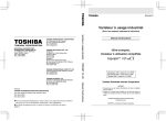
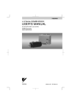
E6581595 1. Read first 1.1 Check product purchase Before using the product you have purchased, check to make sure that it is exactly what you ordered. Caution Mandatory Use an inverter that conforms to the specifications of power supply and three-phase induction motor being used. If the inverter being used does not conform to those specifications, not only will the three-phase induction motor not rotate correctly, it may also cause serious accidents through overheating and fire. Rating label Inverter main unit Brand name Model Power supply Motor capacity VF-nC3 3PH-200V 0.75kW Danger label Carton box Name plate Name plate Danger label Inverter Type Type indication label Instruction manual This manual Inverter rated output capacity Power supply Related input current Related output current TRANSISTOR INVERTER VFNC3S-2022PL 2.2kW-4.1kVA-3HP (1) INPUT OUTPUT U(V) 1PH 200/240 3PH 200/240 50/60 0.1/400 F(Hz) 21.9/18.4 10.0 I(A) S.Ckt 1000A FUSE CC/J 30Amax Serial No. 1328 02021208 0001 Made in . . . . . Motor Overload Protection Class 10 CD-ROM Contains the instruction manual in digital form TSIJ A-1 Setup sheet 1 E6581595 1.2 Contents of the product Explanation of the name plate label. Type 1 Form V F N C 3 S Model name TOSVERT VF-nc3series Number of power phases Input (AC) voltage 1 : 100V to 120V 2 : 200V to 240V 2 0 0 7 P L B - A 2 2 Applicable motor capacity 001 : 0.1kW 002 : 0.2kW 004 : 0.4kW 007 : 0.75kW 015 : 1.5kW 022 : 2.2kW 037 : 4kW Additional functions I None: No filter inside L: Built-in high-attenuation EMI filter None: No filter Operation panel P: Provided S: single-phase None: three-phase Special specification code A:is the number Additional function II None: Standard product B: Base plate type Y: Special specifications Warning: Always shut power off first then check the ratings label of inverter held in a cabinet. A-2 E6581595 1.3 Names and functions 1.3.1 Outside view With cover closed Charge lamp 1 Indicate s there is a high voltage still in the inverter. Do not open the terminal block cover when this lamp is lit becaus e it is dangerous. Cover This is the body or terminal block cover. Always close this cover before operatio n to avoid accidentall y touchin g the terminal block. Door lock hole You can lock the door by shutting it an passing a wire key through this hole. [Front view] Hole for control wire Optional connector (RJ45) Upper caution plate (sticker) (Note 1) Cooling fin (Note 2) Hole for main circuit wiring Ventilation Name plate [Bottom view] [Side view] Note 1) Note 2) Remove the seal as shown on the next page when installing the inverter side by side with other inverters where the ambient temperature will rise above 40°C. Some models are wrapped in plastic. A-3 E6581595 Example of the label 1 [Opening the cover] l 14 l d ¸About the monitor display The LED on the operation panel uses the following symbols to indicate parameters and operations. LED display (numbers) 0 1 2 3 0 1 2 3 4 4 5 5 6 6 7 7 8 8 9 9 - LED display (letters) Aa Bb C c a b c w Dd d Ee e Ff f Gg g H h h k I i i } Jj j Kk Ll l Pp p Qq q Rr r Ss s Tt t Uu u Vv v Ww Xx Yy y Zz Mm m Nn n O o o x A-4 E6581595 Warning • Never touch the internal terminals in the upper right while the cover is open. There is a risk of shock because it carries a high voltage. Prohibited [With cover open] 1 RUN lamp PRG lamp When lit, the inverter is in paramete r settin g mode. When blinking , the inverter is in AUH or Gr-U. % lamp Lit when a frequency is not output with the ON run command. This lamp blinks when operatio n starts. Dispalye d numbers are percents. Hz lamp Displaye d numbers are in Hertz. High voltage caution mark MON lamp The internal terminal in the upper right carries a high voltage. Never touch it. While this is lit, the inverte r is in monito r mode. While blinking , the inverter is in "Past Trip History Details Monitor Display". STOP key While the runing lamp is blinking , pressin g this button slows down and stops the inverter. RUN key Pressing this key while the run lamp is on starts operation. MODE key Switche s between run, settings , and status monitor modes. Setting dial Turning the dial left and right change s the operatio n frequenc y, cycles parameters , and cycles among menus within parameters. EASY key Switches between easy and standard setting modes. A-5 E6581595 1.3.2 Opening the terminal cover Caution 1 Instruction ● When removing and installing the terminal cover with a screwdriver, be sure not to scratch your hand as this results in injury. ● Pressing too hard on the screwdriver may scratch the inverter. ● Always cut the power supply when removing the wiring cover. ● After wiring is complete, be sure to replace the terminal cover. Use the following procedure to remove both the upper and lower terminal block covers. (1) Removing the lower (output and dc terminals) terminal block cover 1) 2) Press in on the screwdriver. Insert a screwdriver or other thin object into the hole indicated with the mark. 3) 4) Pull the terminal cover up at an angle. While pressing on the screwdriver, rotate the terminal cover downward to remove it. A-6 E6581595 (2) Removing the upper terminal (input terminal) block cover 1) 2) 1 Press in on the screwdriver. Insert a screwdriver or other thin object into the hole indicated with the mark. 3) 4) Pull the terminal cover up at an angle. While pressing on the screwdriver, rotate the terminal cover upward to remove it. ★ After wiring is complete, be sure to restore the terminal cover to its original position. A-7 E6581595 1.3.3 Power circuit and control circuit terminal boards In case of the lug connector, cover the lug connector with insulated tube, or use the insulated lug connector. Note 1: EMC plate is supplied as standard. 1) Power circuit terminal board 1 In case of the lug connector, cover the lug connector with insulated tube, or use the insulated lug connector. Screw size Tightening torque M3.5 screw 1.0Nm 8.9lb y in M4 screw 1.4Nm 12.4lb y in M5 screw 3.0Nm 26.6lb y in For details on terminal functions, see 2.3.1. VFNC3-2001 ∼ 2007P R/L1 S/L2 T/L3 M3.5 screw Earth terminal Short-circuit cover M3.5 screw P0 Earth terminal (M4 screw) PA/+ PC/- U/T1 V/T2 W/T3 Earth terminal (M5 screw) EMC plate For installation (Note 1) Earth terminal (M4 screw) * Bend the clips on the wiring port of the terminal cover to connect the PO, PA/+, and PC/- terminals. A-8 E6581595 VFNC3-2015 ∼ 2037P R/L1 M4 screw S/L2 T/L3 Earth terminal 1 Short-circuit cover M4 screw P0 Earth terminal M4 screw: 2015, 2202 M5 screw: 2037 PA/+ PC/- U/T1 V/T2 W/T3 Earth terminal (M5 screw) EMC plate For installation (Note 1) Earth terminal M4 screw: 2015, 2202 M5 screw: 2037 * Bend the clips on the wiring port of the terminal cover to connect the PO, PA/+, and PC/- terminals. VFNC3S-1001~1004P,2001~2007PL R/L1 S/L2/N Earth terminal Grounding capacitor switch (2001 to 2007 PL only) M3.5 screw M3.5 screw Short-circuit cover P0 PA/+ PC/- U/T1 V/T2 W/T3 Earth terminal (M5 screw) Earth terminal Earth terminal (M4 screw) EMC plate For installation (Note 1) * Bend the clips on the wiring port of the terminal cover to connect the PO, PA/+, and PC/- terminals. A-9 E6581595 VFNC3S-1007P,2015PL,2022PL R/L1 S/L2/N Earth terminal Grounding capacitor switch (2015, 2022 PL only) M4 screw 1 Short-circuit cover M4 screw P0 PA/+ PC/- U/T1 V/T2 W/T3 Earth terminal (M5 screw) EMC plate For installation (Note 1) Earth terminal (M4 screw) Earth terminal (M4 screw) * Bend the clips on the wiring port of the terminal cover to connect the PO, PA/+, and PC/- terminals. When using a crimping terminal, be sure to cover the fastener with an insulating tube or use an insulated crimping terminal. Note 1) The EMC plate is optional. 2) Grounding capacitor switch Single-phase 240 V models have a built-in high-attenuation noise filter and are grounded via a capacitor. A switch makes for easy switching to reduce leakage current from the inverter and the load on the capacitor. However, be careful, as reducing the load means non-conformity with the EMC standard on the inverter itself. Always do switching with the power off. Pressing this switches the grounding capacitor's capacity from small to large. (Default setting) Pulling this switches the grounding capacitor's capacity from large to small. This reduces the leakage current. A-10 E6581595 3) Control circuit terminal board The control circuit terminal board is common to all equipment. FLA FLB FLC CC VI P5 FM 1 OUT NO CC F R S1 S2 P24 Optional connector (RJ45) Screw size Recommended tightening torque M2.5 screw 0.5 Nxm Wire size Solid wire: 0.3 ∼ 1.5 (mm2) Stranded wire: 0.3 ∼ 1.5 (mm2) (AWG 22 ∼ 16) Sheath strip length: 6 (mm) Screwdriver: Small-sized flat-blade screwdriver (Blade thickness: 0.5 mm, blade width: 3.5 mm) See 2.3.2 for details on all terminal functions. A-11 4.4 lbxin E6581595 1.4 Notes on the application 1.4.1 Motors When the VF-nC3 and the motor are used in conjunction, pay attention to the following items. Caution 1 Mandatory Use an inverter that conforms to the specifications of power supply and three-phase induction motor being operated. If the inverter being used does not conform to those specifications, not only will the three-phase induction motor not rotate correctly, but it may cause serious accidents through overheating and fire. Comparisons with commercial power operation. The VF-nC3 Inverter employs the sinusoidal PWM system. However, the output voltage and output current are not perfect sine waves, they have a distorted wave that is close to sinusoidal waveform. This is why compared to operation with a commercial power there will be a slight increase in motor temperature, noise and vibration. Operation in the low-speed area When running continuously at low speed in conjunction with a general purpose motor, there may be a decline in that motor's cooling effect. If this happens, operate with the output decreased from rated load. To carry out low-speed operation continuously at the rated torque, we recommend to use a inverter rated motor or a forced cooled motor designed for use with an inverter. When operating in conjunction with a inverter rated motor, you must change the inverter's motor overload protection level to VF motor use. Adjusting the overload protection level The VF-nC3 Inverter protects against overloads with its overload detection circuits (electronic thermal). The electronic thermal's reference current is set to the inverter's rated current, so it must be adjusted in line with the rated current of the motor being used in combination. High speed operation at and above 60Hz Operating at frequencies greater than 60Hz will increase noise and vibration. There is also a possibility this will exceed the motor's mechanical strength limits and the bearing limits so you should inquire to the motor's manufacturer about such operation. Method of lubricating load mechanisms Operating an oil-lubricated reduction gear and gear motor in the low-speed areas will worsen the lubricating effect. Check with the manufacturer of the reduction gear to find out about operable gearing area. A-12 E6581595 Low loads and low inertia loads The motor may demonstrate instability such as abnormal vibrations or overcurrent trips at light loads of 50 % or under of the load percentage, or when the load's inertia moment is extremely small. If that happens reduce the carrier frequency. Occurrence of instability Unstable phenomena may occur with the load and motor combinations shown below. ⋅ Combined with a motor that exceeds applicable motor ratings for the inverter ⋅ Combine with a much smaller motor according to the applicable motor rating of the inverter. ⋅ Combined with special motors To deal with the above lower the settings of inverter carrier frequency. ⋅ Combined with couplings between load devices and motors with high backlash When using the inverter in the above combination, use the S-pattern acceleration/deceleration function, or when vector control is selected, adjust the speed control response or switch to V/f control mode. ⋅ Combined with loads that have sharp fluctuations in rotation such as piston movements In this case, adjust the response time (inertial moment setting) during vector control or switch to V/f control. Braking a motor when cutting off power supply A motor with its power cut off goes into free-run, and does not stop immediately. To stop the motor quickly as soon as the power is cut off install an auxiliary brake. There are different kinds of brake devices, both electrical and mechanical. Select the brake that is best for the system. Load that produces regenerative torque When combined with a load that produces regenerative torque, the overvoltage or overcurrent protection function may be activated to trip the inverter. A-13 1 E6581595 Motors with a brake When motors with a brake are directly connected to the inverter's output, the brake cannot be released at startup because of low voltage. Wire the brake circuit separately from the main circuit. MC2 MC2 B 1 B MC1 MC1 IM 3-phase power source FLB FLC S2 (ST) CC IM 3-phase power source MC3 NO CC P24 OUT + – RY MC1 RY MC3 MC2 MC3 MC2 Circuit diagram 1 Circuit diagram 2 In circuit diagram 1, the brake is turned on and off through MC2 and MC3. If you do not wire it as shown in diagram 1, an over-current trip may occur because of a bound current during brake operation. (Example of running preparation ST assigned to terminal S2.) In circuit diagram 2, the brake is turned on and off by using low-speed signal OUT. In some situations, such as with elevators, turning the brake on and off with a low-speed signal may be appropriate. Be sure to contact us before designing your system. 1.4.2 Inverters Protecting inverters from overcurrent The inverter has an overcurrent protection function. The programmed current level is set to the inverter's maximum applicable motor. If the motor used has a small capacity, the overcurrent level and the electronic thermal protection must be readjusted. If adjustment is necessary, see 5.13, and make adjustments as directed. Inverter capacity Do not use a small-capacity (kVA) inverter to control the operation of a large-capacity motor (two-class or more larger motor), no matter how light the load is. Current ripple will raise the output peak current making it easier to set off the overcurrent trip. A-14 E6581595 Power factor correction capacitor Power factor correction capacitors cannot be installed on the output side of the inverter. When a motor is run that has a power factor correction capacitor attached to it, remove the capacitors. This can cause inverter malfunction and capacitor destruction. U/T1 Inverter 1 IM V/T2 W/T3 Remove the power factor correction capacitor and surge absorber Power factor correction capacitor Operating at other than rated voltage Connections to voltages other than the rated voltage described in the rating label cannot be made. If a connection must be made to a power supply other than one with rated voltage, use a transformer to raise or lower the voltage to the rated voltage. Circuit breaking when two or more inverters are used on the same power line. MCCB1 MCCB2 (circuit breaking fuse) INV1 MCCB3 INV2 MCCB: No-fuse breaker MCCBn+1 INVn Breaking of selected inverter There is no fuse in the inverter's main circuit. Thus, as the diagram above shows, when more than one inverter is used on the same power line, you must select interrupting characteristics so that only MCCB2 to MCCBn+1 will trip and the MCCB1 will not trip when a short occurs in the inverter (INV1). When you cannot select the proper characteristics install a circuit interrupting fuse behind MCCB2 to MCCBn+1. If power supply distortion is not negligible If the power supply distortion is not negligible because the inverter shares a power distribution line with other systems causing distorted waves, such as systems with thyristors or large-capacity inverters, install an input reactor to improve the input power factor, to reduce higher harmonics, or to suppress external surges. A-15 E6581595 Disposal See chapter 16. 1.4.3 1 What to do about the leakage current Caution Current may leak through the inverter's input/output wires because of insufficient electrostatic capacity on the motor with bad effects on peripheral equipment. The leakage current’s value is affected by the carrier frequency and the length of the input/output wires. Test and adopt the following remedies against leak current. (1) Leakage current from the inverter main unit Some of these inverters are equipped with a ground capacitor compliant with the EMC directive which gives them a comparatively higher value than a normal inverter. Take this into consideration when selecting a leakage breaker. For details, see "Leakage current" (E6580977) in the separate user manual. (2) Effects of leak current across ground Leakage current may flow not just through the inverter system but also through ground wires to other systems. Leakage current will cause earth leakage breakers, leakage current relays, ground relays, fire alarms and sensors to operate improperly, and it will cause superimposed noise on the TV screen or display of incorrect current detection with the CT. Power supply ELCB Inverter ELCB Inverter Leakage current path across ground A-16 IM IM E6581595 Remedies: 1.If there is no radio-frequency interference or similar problem, detach the built-in noise filter capacitor, using the grounding capacitor disconnecting switch. (See 1.3.3-2)) 2.Reduce PWM carrier frequency. The setting of PWM carrier frequency is done with the parameter . Although the electromagnetic noise level is reduced, the motor acoustic noise is increased. 3. Use high frequency remedial products for earth leakage breakers (3) Affects of leakage current across lines Thermal relays CT Inverter Power supply IM A Leakage current path across wires (1) Thermal relays The high frequency component of current leaking into electrostatic capacity between inverter output wires will increase the effective current values and make externally connected thermal relays operate improperly. If the wires are more than 50 meters long, it will be easy for the external thermal relay to operate improperly with models having motors of low rated current (several A(ampere) or less), because the leakage current will increase in proportion to the motor rating. Remedies: 1.Use the electronic thermal built into the inverter. (See 3.5) The setting of the electronic thermal is done using parameter , . 2.Reduce the inverter's PWM carrier frequency. However, that will increase the motor's magnetic noise. The setting of PWM carrier frequency is done with the parameter . (See 6.11 in E6581595) 3.This can be improved by installing 0.1µ~0.5µF - 1000V film capacitor to the input/output terminals of each phase in the thermal relay. U/T1 IM V/T2 W/T3 Thermal relays A-17 1 E6581595 (2) 1 CT and ammeter If a CT and ammeter are connected externally to detect inverter output current, the leak current's high frequency component may destroy the ammeter. If the wires are more than 50 meters long, it will be easy for the high frequency component to pass through the externally connected CT and be superimposed on and burn the ammeter with models having motors of low rated current (several A(ampere) or less), because the leakage current will increase in proportion to the motor's rated current. Remedies: 1.Use a meter output terminal in the inverter control circuit. The load current can be output on the meter output terminal (FM). If the meter is connected, use an ammeter of 1mAdc full scale or a voltmeter of 10V full scale. 0-20mAdc (4-20mAdc) can be also output. (See 5.6) 2.Use the monitor functions built into the inverter. Use the monitor functions on the panel built into the inverter to check current values. (See 8.2.1) 1.4.4 Installation Installation environment The VF-nC3 Inverter is an electronic control instrument. Take full consideration to installing it in the proper operating environment. Warning • Do not place any inflammable substances near the VF-nC3 Inverter. If an accident occurs in which flame is emitted, this could lead to fire. Prohibited • Operate under the environmental conditions prescribed in the instruction manual. Operations under any other conditions may result in malfunction. Mandatory Caution • Do not install the VF-nC3 Inverter in any location subject to large amounts of vibration. This could cause the unit to fall, resulting in bodily injury. Prohibited Mandatory • Check to make sure that the input power voltage is +10%, -15% of the rated power voltage written on the rating label (±10% when the load is 100% in continuous operation) If the input power voltage is not +10%, -15% of the rated power voltage (±10% when the load is 100% in continuous operation) this may result in fire. A-18 E6581595 • • • Do not install in any location of high temperature, high humidity, moisture condensation and freezing and avoid locations where there is exposure to water and/or where there may be large amounts of dust, metallic fragments and oil mist. Do not install in any location where corrosive gases or grinding fluids are present. Operate in areas where ambient temperature ranges from -10°C to 60°C. Operation over 40°C is allowed when the top label is peeled off. When installing the inverter where the ambient temperature will rise above 50°C, remove the label (seal) from the top and operate it at a current lower than the rated one. (See 6.11 in E6581595.) [Position for measuring ambient temperature] 5cm 5cm Measurement position 5cm Measurement position Note: • The inverter is a heat-emitting body. Make sure proper space and ventilation is provided when installing in the cabinet. When installing inside a cabinet, we recommend the top seal peeled off although 40°C or less. Do not install in any location that is subject to large amounts of vibration. Note: • If the VF-nC3 Inverter is installed in a location that is subject to vibration, anti-vibration measures are required. Please consult with Toshiba about these measures. If the VF-nC3 Inverter is installed near any of the equipment listed below, provide measures to insure against errors in operation. Solenoids: Brakes: Magnetic contactors: Fluorescent lights: Resistors: Resistors A-19 Attach surge suppressor on coil. Attach surge suppressor on coil. Attach surge suppressor on coil. Attach surge suppressor on coil. Place far away from VF-nC3 Inverter. 1 E6581595 How to install Warning 1 Prohibited Mandatory • Do not install or operate the inverter if it is damaged or any component is missing. This can result in electric shock or fire. Please consult your local sales agency for repairs. Call your local sales agency for repairs. • Mount the inverter on a metal plate. The rear panel gets very hot. Do not install in an inflammable object, this can result in fire. • Do not operate with the front panel cover removed. This can result in electric shock. • An emergency stop device must be installed that fits with system specifications (e.g. shut off input power then engage mechanical brake). Operation cannot be stopped immediately by the inverter alone, thus risking an accident or injury. • All options used must be those specified by Toshiba. The use of any other option may result in an accident. Caution Mandatory • The main unit must be installed on a base that can bear the unit's weight. If the unit is installed on a base that cannot withstand that weight, the unit may fall resulting in injury. • If braking is necessary (to hold motor shaft), install a mechanical brake. The brake on the inverter will not function as a mechanical hold, and if used for that purpose, injury may result. (1) Normal installation Select an indoor location with good ventilation, and then install it upright on a flat metal plate. When installing multiple inverters, leave at least 5 cm of space between each inverter and install them aligned horizontally. When using the inverter in locations with temperatures above 40°C, remove the caution plate (sticker) on top of the inverter before use. Current reduction is necessary in locations that exceed 50°C. 10 cm or more 5 cm or more VFnC3 5 cm or more 10 cm or more (2) Side-by-side installation To align the inverters side-by-side horizontally, remove the caution plate (sticker) on top of the inverter before use. Current reduction is necessary in locations that exceed 40 °C. A-20 E6581595 10 cm or more Remove seals on top VFnC3 VFnC3 VFnC3 10 cm or more 1 The space shown in the diagram is the minimum allowable space. Because air cooled equipment has cooling fans built in on the top or bottom surfaces, make the space on top and bottom as large as possible to allow for air passage. Note: Do not install in any location where there is high humidity or high temperatures and where there are large amounts of dust, metallic fragments and oil mist. Calorific values of the inverter and the required ventilation About 5% of the rated power of the inverter will be lost as a result of conversion from AC to DC or from DC to AC. In order to suppress the rise in temperature inside the cabinet when this loss becomes heat loss, the interior of the cabinet must be ventilated and cooled. The amount of forcible air-cooling ventilation required and the necessary heat discharge surface quantity when operating in a sealed cabinet according to motor capacity are as follows. Notes 1) The heat loss for the optional external devices (input reactor, DC reactor, radio noise reduction filters, etc.) is not included in the calorific values in the table 2) Case of 100% Load Continuation operation. Voltage class Single-phase 100V class Single-phase 200V class Three-phase 300V class Operating motor capacity (kW) 0.1 0.2 0.4 0.75 0.1 0.2 0.4 0.75 1.5 2.2 0.1 0.2 0.4 0.75 1.5 2.2 4.0 Inverter type VFNC3S- VFNC3S- VFNC3- 1001P 1002P 1004P 1007P 2001PL 2002PL 2004PL 2007PL 2015PL 2022PL 2001P 2002P 2004P 2007P 2015P 2022P 2037P Calorific values 4kHz 13 18 29 48 13 18 27 44 72 93 13 16 24 41 73 85 128 A-21 12kHz 14 20 33 54 14 20 31 43 83 102 14 18 28 45 85 90 133 Amount of forcible air cooling ventilation required (m3/min) 4kHz 12kHz 0.07 0.08 0.10 0.11 0.16 0.19 0.27 0.31 0.07 0.08 0.10 0.11 0.15 0.18 0.25 0.24 0.41 0.47 0.53 0.53 0.07 0.08 0.09 0.10 0.14 0.16 0.23 0.26 0.41 0.48 0.48 0.51 0.73 0.75 Heat discharge surface area required for sealed storage cabinet (m3) 4kHz 12kHz 0.26 0.28 0.36 0.40 0.58 0.66 0.96 1.08 0.26 0.28 0.36 0.40 0.54 0.62 0.88 0.86 1.44 1.66 1.86 2.04 0.26 0.28 0.32 0.36 0.48 0.56 0.82 0.90 1.46 1.70 1.70 1.80 2.56 2.66 E6581595 Panel designing taking into consideration the effects of noise 1 The inverter generates high frequency noise. When designing the control panel setup, consideration must be given to that noise. Examples of measures are given below. • Wire so that the main circuit wires and the control circuit wires are separated. Do not place them in the same conduit, do not run them parallel, and do not bundle them. • Provide shielding and twisted wire for control circuit wiring. • Separate the input (power) and output (motor) wires of the main circuit. Do not place them in the same conduit, do not run them parallel, and do not bundle them. • Ground the inverter ground terminals ( ). • Install surge suppressor on any magnetic contactor and relay coils used around the inverter. • Install noise filters if necessary. • To comply with the EMC directives, install the optional EMC plate and fix the shield to it. • Install EMC plate and use shielded wires. EMC Plate A-22 E6581595 Installing more than one unit in a cabinet If you are installing two or more inverters in one cabinet, pay attention to the following. • Inverters may be installed side by side with each other with no space left between them. • When installing inverters side by side, detach the caution label on the top surface of each inverter and use them where the ambient temperature will not rise above 40°C. • When using inverters where the ambient temperature will rise above 40°C, leave a space of 5 cm or more between them and remove the caution label from the top of each inverter, or operate each inverter at a current lower than the rated one. • Ensure a space of at least 20 centimeters on the top and bottom of the inverters. • Install an air deflecting plate so that the heat rising up from the inverter on the bottom does not affect the inverter on the top. Ventilation fan Inverter Air deflecting plate Inverter A-23 1