1
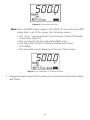
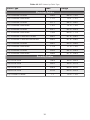
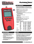
Calibration Mode
When the CAL button is pressed, the “Cal” icon appears in the lower left
corner of the display screen. The icons and values described in Table 6
appear in the LCD display screen when the unit is set to Calibration Mode.
Table 6. Calibration Mode Icons and Values
Icons and Values
Description
Cable Length
The last entered cable length appears (in units of
feet or meters) in the top row of the LCD
display screen.
Adjustment
Indicator
The adjustment indicator icon, denoted by two
Up/Down arrows, indicates that cable length can
be adjusted while in Calibration Mode.
▪▪The icon displays to the left of the last inputted
cable length.
NVP Icon
The “NVP” icon appears in the bottom row of the
LCD display screen.
▪▪Three dash lines “- - -” appear to the left of
the “NVP” icon demonstrating that the NVP
has not been calculated for the entered cable
length.
Note: Refer to the Using Calibration Mode section to learn how to
calculate the NVP of a cable.
11