1
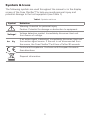
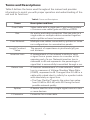
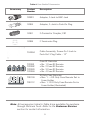
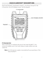
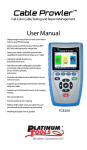
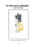
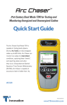
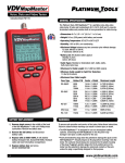
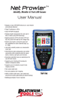
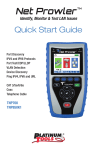
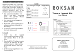
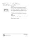
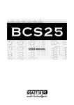
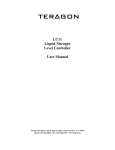
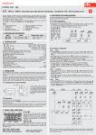
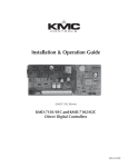
Coax Clarifier
TM
Test. Identify. Qualify.
User Manual
Coax Run Mapping
Maps runs through splitters to show an
accurate picture of the coax system layout
using up to 4 Coax RF Remotes. Up to 12
ID Only Coax Remotes also available for
wiremapping on home runs.
Cable Length
Determines cable run length and reports
the location of an open or unterminated
cable.
Quality of Network
Measures overall network quality and
clearly depicts network reading as both a
bar graph and a digital return loss number,
measured in dB.
Tone Tracing
Traces coax runs with four unique tones
to quickly distinguish between respective
outlets.
See video demonstrations at:
www.platinumtools.com
Coax Clarifier
TM
Test. Identify. Qualify.
Table of Contents
About this Manual...................................................................1
Symbols and Icons..............................................................2
Terms and Descriptions......................................................3
Safety Information..............................................................4
Accessories.....................................................................4
Design Features.......................................................................6
Coax Clarifier™ Description.....................................................7
F-Connector................................................................7
LCD Display Screen............................................................8
Keypad.................................................................14
Operations.....................................................................16
Turning the Unit On/Off...................................................16
Automatic Power Down...................................................16
Cable Testing General Guidelines....................................17
Using Tone Mode.............................................................18
Trace Cable Runs..............................................................18
Measure Network Insertion Loss.....................................19
Prepare Test Unit........................................................19
Calibrate dB Loss Meter.............................................20
Measure Network Insertion Loss................................21
Test Splitters...............................................................21
Using Length Mode..........................................................22
Measure Cable Length...............................................22
Adjust Length Constant Value...................................24
Length Constant Accuracy..........................................26
Using ID Mode...................................................................27
RF Remote Battery Life...............................................29
Using Quality Mode..........................................................29
RF Remotes and Network Quality..............................30
Measure Network Quality..........................................30
Maintenance. ..............................................................32
Coax Clarifier™ Battery Replacement.............................32
RF Remote Battery Replacement....................................32
Cleaning.......................................................................33
Storage....................................................................33
Customer Service...................................................................34
Contacting Platinum Tools ..................................................34
Additional Accessories and Kits......................................34
Warranty Information.......................................................37
Product Registration..........................................................37
Disposal......................................................................37
Returns........................................................................37
Specifications....................................................................38
ABOUT THIS MANUAL
The Coax Clarifier™ is a self contained, hand-held, battery powered
analyzer used by contractors, repair technicians, and other authorized
users. This device is used to quickly map coax cable runs, measure
network performance, determine cable length, and locate faults in “Dark”
(unpowered) residential and business cable networks. The test unit offers
the following features:
Feature
Function
Length Testing
Determines cable length and reports distance to an
open (unterminated) cable.
Coax Run Mapping
Identifies cables and determines their location by
mapping up to 4 runs through a splitter using Coax
RF remotes and up to 12 cables using ID Only Coax
remotes.
Quality Testing
Measures overall network quality and clearly depicts
network reading as both a bar graph and a digital
return loss number, measured in decibels (dB).
Tone Tracing
Traces coax runs, with the use of a tone probe, using
four tones to easily distinguish between cable outlets
and quickly map the network layout.
Insertion Loss
Measures the insertion loss of a single coax run.
Fault Detection
Identifies Open and Short cable faults.
1
Symbols & Icons
The following symbols are used throughout the manual or in the display
screen of the Coax Clarifier™ to help you avoid personal injury and
potential damage to the test equipment (see Table 1).
Table 1. Symbols and Icons
Symbol
Definition
!
Warning: Potential for personal injury
Caution: Potential for damage or destruction to equipment.
Voltage!
Voltage detection symbol. Immediately disconnect test unit
from source of voltage.
Act Sig
If an active signal is detected, immediately disconnect test unit
from active signal source. If the unit is not disconnected from
the source, the Coax Clarifier™ will turn off after 90 seconds.
Conformité Européenne. Conforms with European Economic
Area directives.
Disposal information.
2
Terms and Descriptions
Table 2 defines the terms used throughout the manual and provides
information to assist you with proper operation and understanding of the
unit and its functions.
Table 2. Terms and Descriptions
Terms
Description and Uses
Coax Cable
Video cable with a single pair (2 pin) wiring system.
▪▪Common coax cable types are RG6 and RG59.
Run
An end-to-end cable connection. Run can refer to a
single cable or multiple cables connected together
with a splitter or barrel connector.
Coax Network
Multiple coax cables connected by splitters or home
run configurations to concentration panels.
Length Constant
Value
The amount of capacitance in picofarads (pF) per
unit distance.
Insertion Loss
A measurement of the network’s ability to carry
a signal from a power source to a receiver at the
opposing end of a run. Network insertion loss is
measured in dB and represents the percentage of
signal that is successfully transmitted through a run.
Return Loss
A common measurement of coax networks, return
loss is a measure of Voltage Standing Wave Ratio
(VSWR), expressed in dB. It ranges from 0.0 dB for a
cable with a dead short to infinity for a perfect cable
with absolutely no signal loss.
▪▪The Coax Clarifier™ reports the return loss value
from 0.0 dB to 40.0 dB, with 40.0 being the best
possible network quality.
Splitter
A device used to route a single signal source to two
or more devices.
F-Connector
Connector for a coax cable.
3
Safety Information
To ensure safe operation of the Coax Clarifier™, follow the instructions
carefully and observe the warning and caution messages listed in Table
3. Failure to observe warnings can result in severe injury or death and can
damage the unit.
Table 3. Safety Information
Notification
Definition
The Coax Clarifier™ is designed for use on unenergized
cabling systems. Connecting the Coax Clarifier™ to live AC
power may damage the unit and pose a safety hazard for
the user.
Do not place equipment or its accessories in the trash.
Items must be properly disposed in accordance with local
regulations.
ACCESSORIES
The accessories listed in Table 4 are used with the Coax Clarifier™
to identify runs and test coax networks. The provided accessories are
dependent on the kit you purchased. The Additional Accessories and
Kits section contains a detailed list of each kit as well as additional
products that can help make testing easier.
4
Table 4. Coax Clarifier™ Accessories
Accessory
Remote
Remote
1
2
1
5
9
2
Remote
Remote
3
3
4
4
6
7
8
10
11
12
Product
Number
Description
18303
Adapter, F-Jack to BNC Jack
18304
Adapter, F–Jack to Push-On Plug
18301
F-Connector Coupler, F81
18306
F-Terminator Plug
TCA004
Cable Assembly, Screw-On F-Jack to
Push-On F-Plug Cable – 12”
TCR001
TCR002
TCR003
TCR004
TRK104
TRK112
Coax RF Remotes
▪▪No. 1 Coax RF Remote
▪▪No. 2 Coax RF Remote
▪▪No. 3 Coax RF Remote
▪▪No. 4 Coax RF Remote
ID Only Coax Remotes
▪▪Nos. 1 – 4 ID Only Coax Remote Set in
Foam Holder
▪▪Nos. 1-12 ID Only Coax Remote Set in
Foam Holder (Illustrated)
Note: All accessories listed in Table 4 are available for purchase
through Platinum Tools. Refer to the Customer Service
section for contact information.
5
DESIGN FEATURES
▪▪Easy to operate
▪▪One pass coax cable run mapping
▪▪Tests through splitters
▪▪Identifies open (unterminated) cables
▪▪Extra large seven-segment, backlight LCD screen with icons that
clearly display test results
▪▪Displays coax cable run quality
▪▪Tests and grades splitter performance
▪▪Measures length of coax cable in feet or meters
▪▪Identifies up to 4 RF remotes and 12 ID Only Coax remotes
▪▪Automatic pre-test voltage checks
▪▪Measures single cable length up to 1,500 ft
▪▪Tone generator with selectable tone cadence to easily trace cable runs
▪▪Conserves power and supports long battery life with Auto-off feature
and battery low icon
▪▪Four AA alkaline batteries provided with your purchase
6
Coax Clarifier™ Description
The Coax Clarifier™, illustrated in Figure 1, has three main parts: the
F-Connector, the LCD display screen, and the keypad.
Figure 1. Coax Clarifier™
F-Connector
One F-Connector is located at the top of the Coax Clarifier™. The
connector enables you to test and measure single cables and coax
networks.
Note: An F-Connector coupler is provided with your purchase of the
Coax Clarifier™.
7
LCD Display Screen
The Coax Clarifier™ has a high contrast, backlight LCD display screen,
shown in Figure 2 below. The LCD display screen shows the following:
cable conditions, test modes and related icons, calibration icon, voltage
detected warning, active signal warning, and battery capacity.
Battery Low Icon
Detected Remotes
}
Voltage Detected Warning
Tone Mode
Length Mode
Cable Conditions
Calibration Icon
Quality Mode and
Bar Graph
Cable Types
Measured Length
Length Constant Value
Return Loss Icon
Figure 2. LCD Display Screen
Cable Conditions
The device checks for three cable conditions during testing: Open, Short,
and Terminated. The cable conditions, explained in Table 5, appear in a
column below the battery low icon in the LCD display screen.
Table 5. Cable Conditions
Cable Conditions
Description
Open
An “Open” error indicates a wire connection within
the cable is not continuous throughout the length
of the cable.
Short
The “Short” icon appears when the two wires
within a cable are electrically connected. This is
also known as a short circuit.
Terminated
The “Terminated” icon will appear when the far end
of the run has an F-Terminator Plug in place or is
wired to a device.
8
ID Mode
When the Coax Clarifier™ is set to ID Mode, the “ID” and “RF” icons
appear in the top left corner of the LCD display screen. Table 6 describes
the numbers and icons that appear in the display screen according to three
testing scenarios.
Table 6. ID Mode Numbers and Icons
Test Scenario
Detected Remotes
Displayed Numbers and Icons
Indentified remotes 1-12 display in the top two rows
of the LCD display screen.
▪▪When an ID Only Coax remote is detected, the
“RF” icon disappears from view.
▪▪The “IdLE” icon appears in the lower right
corner of the display screen when mapping is
complete and all remotes are detected.
Unterminated Runs
Poor Network Quality
RF and ID Only Coax remotes are not identified on
unterminated runs.
▪▪The “Open” icon appears in the right side of
the display screen to indicate the network is
unterminated.
▪▪The halt icon, “HLt”, displays in the right side of
the screen demonstrating the unit is idle and the
test was incomplete (see Figure 3).
ID mode does not function on a coax network with a
poor quality reading (< 17 dB).
▪▪When the network quality is low, mapping stops,
the “QUALITY” icon flashes, and the “HLt” icon
appears in the lower right corner of the display
screen (see Figure 4).
Figure 3. ID Mode with Unterminated Run
Figure 4. ID Mode with Poor Network Quality
9
Note: When the network quality is low, be sure that all cable ends
are terminated. Unterminated cables result in signal loss. Use
F-Terminator Plugs as needed to improve network quality.
Length Mode
The “Length” icon appears in the left side of the LCD display screen when
the LENGTH button is pressed. When the unit is set to measure cable
length, the length reading and measurement specifications described in
Table 7 appear in the LCD display screen (see Figure 5).
Table 7. Length Mode Measurement Specifications
Length Specifications
Cable Types
Description
The cable types (RG6, RG59, or no specified
type) appear in the lower left of the LCD display
screen.
▪▪Each type of cable has its own length constant
value, which is used to properly measure cable
length.
Length Constant Value
A value measured in picofarads (pF) per foot or
meter appears in the lower left corner of the
LCD display screen. This value corresponds to
the selected cable type and can be adjusted at
any time.
Measured Length
The length of the measured cable displays in
units of feet or meters in the lower right corner
of the screen.
Figure 5. Length Measurement for Unspecified Cable
10
Note: Refer to the Using Length Mode section to learn how to
change the unit of measurement, adjust the length constant
value for each cable type, and measure cable length.
Quality Mode
When the QUALITY button is pressed the “Quality” icon displays in the
lower right corner of the LCD display screen and a bouncing ball activity
indicator is shown in the lower left corner of the screen. When testing
network quality, the following icons and values appear in the screen (see
Figure 6):
▪▪Bar Graph – The bar graph depicts the overall quality of the network
being tested. The bar graph, appearing in the lower right of the screen,
corresponds to the measured return loss and will adjust (increasing or
decreasing in the visual bars shown) as the return loss value fluctuates.
Refer to the Using Quality Mode section for a description of what each
bar represents in terms of network quality.
▪▪Return Loss (RL) – When the unit produces a return loss value for the
network quality, the “RL” icon appears to the left of the measured return
loss value. Return loss is measured in dB and displays in the lower right
corner of the screen.
Figure 6. Return Loss Measurement in Quality Mode
Note: Using F-Terminator Plugs on unterminated cable ends will
improve network quality and lower return loss.
11
Tone Mode
When the TONE button is pressed, the “Tone” icon appears in the middle
of the LCD display screen and a bouncing ball activity indicator is shown
in the lower left corner of the screen. The “RF” symbol will display to the
left of the “Tone” icon when you set Tone Mode to measure the network’s
insertion loss. When using Tone Mode, the icons and values described in
Table 8 appear in the LCD display screen.
Table 8. Tone Mode Icons and Values
Icons and Values
Description
Tone Path Selection
The selected cadence is transmitted on the coax
pin (“P”), the coax shield (“S”), or both the pin and
shield (“PS”).
▪▪The icons related to the current tone path selection
appear in the lower left corner of LCD display
screen.
Frequency
If the unit is set to measure network insertion
loss, one of the following frequencies (measured
in MHz) displays in the lower right corner of the
screen: 10.0, 20.0, 30.0, or 40.0 (see Figure 7).
Cadence
If the unit is set to identify cable runs, one of the
following tone options appears in the lower right
corner of the display screen: HL1, HL2, Hi, and Lo
(see Figure 8).
Figure 7. RF Tone with 10.0 MHz Frequency
Figure 8. Tone Mode with Lo Cadence
Note: Refer to the Using Tone Mode section to learn how to run
the two tone tests.
12
Cal
The “Cal” icon flashes in the middle of the LCD display screen when
editing the length constant value in Length Mode and during calibration
testing. The Coax Clarifier™ performs a calibration and self-test pass
before starting Quality or ID testing.
If calibration fails, the “Cal” icon flashes to indicate that the unit failed
to initialize properly. Hold down the POWER button to turn the unit off or
press the test mode button again (QUALITY or ID) to proceed with testing.
Battery Low
The battery low icon appears when the battery is nearing depletion.
The symbol flashes when there is 30 minutes of remaining battery life
indicating the battery needs to be replaced. Results may be unreliable at
this point.
Voltage Detected Warning (Voltage!)
If voltage is detected on the cable the “Voltage!” icon flashes. A check for
voltage is performed before each test and during most tests when looping
or changing test parameters. If voltage is detected, testing stops. If the
icon appears, the Coax Clarifier™ should be immediately disconnected
from the source of the voltage.
Active Signal Warning (Act Sig)
When an active signal is detected, the “Act Sig” message flashes at the
bottom of the display screen. If an active signal is found, the unit should
be immediately disconnected from the signal source. The Coax Clarifier™
will automatically turn off after 90 seconds if the unit is not disconnected
from the active signal.
13
Keypad
The Coax Clarifier™ is equipped with seven buttons, illustrated in Figure 9.
Four buttons, appearing in the top two rows of the keypad, are used to operate
test modes (ID, Length, Quality, and Tone). Two Up/Down buttons are used to
edit. One button is used to power the unit On/Off and toggle the backlight On/
Off. The button functions are explained in Table 9.
Toggle Units
Quality
Length
ID
Up/Down
Tone
Power/Backlight
Figure 9. Keypad
Table 9. Keypad
Button
Function
Length
The Length Mode button is used to measure the length of a
single, unterminated cable in feet or meters.
▪▪A short press of the Length and Quality buttons simultaneously
toggles between length measurement units of feet and meters.
▪▪A long press (two seconds) of the Length button allows you to
edit the length constant.
Quality
The Quality Mode button measures the overall quality of a coax
network by measuring the network’s return loss (calibrated in dB).
▪▪A short press of the button runs a loop test on the network every
30 seconds.
ID
The ID Mode button is used with ID Only Coax remotes and RF
remotes to identify cable runs.
▪▪A short press of the ID button runs a single scan of the network.
▪▪ID Mode scans and identifies up to 4 RF remotes or 1-12
possible ID Only Coax remotes in the network.
14
Table 9. Keypad (Continued)
Button
Function
Tone
The Tone Mode button offers two types of testing: tone tracing
(TONE) and measuring network insertion loss (RF TONE).
TONE
▪▪A short press of the button transmits a 0 – 1 kHz cadence from
the unit through the connected cable.
▪▪Subsequent presses of the Tone button steps through the three
tone path options (coax pin, coax shield, or coax pin and shield).
RF TONE
Used to determine the network insertion loss (measured in dB)
with the use of a compatible dB Loss meter.
▪▪A short press of the Tone button transmits a frequency from the
unit through the connected cable.
Up/Down
▪▪In Tone Mode, the Up and Down buttons allow you to select a
Power
▪▪A short press of the Power button enters Quality Mode.
▪▪Short presses of any test mode button turns the unit On.
▪▪Subsequent presses of the Power button toggle the backlight
tone test (TONE or RF TONE) and their respective cadence or
frequency.
▪▪In Length mode, the Up and Down buttons are used to select
cable types and adjust (increment/decrement) length constant
values.
On and Off.
▪▪A long press (two seconds) of the Power button turns the
unit off.
15
Operations
To ensure safe operation of the Coax Clarifier™, follow the instructions
carefully and pay attention to warning and caution symbols. Failure to
observe warnings can result in severe injury or death and can damage the
unit.
Turning the Unit On/Off
Turn Unit On
▪▪Press any test mode button to turn the unit ON. The LCD display
screen updates according to the test mode selected.
Turn Unit Off
▪▪Press and hold down the POWER button for two seconds to turn the
unit OFF. The display screen will go blank.
Automatic Power Down
The Coax Clarifier™ automatically turns off after a period of inactivity to
conserve battery power. The automatic power down feature is dependent
on which test modes are in use and if voltage is detected in the network
(see Table 10).
Table 10. Automatic Power Down.
Test Mode
Time
Tone
60 minutes
Length
5 minutes
Quality
5 minutes
ID
5 minutes
Voltage Detected
90 seconds
16
Cable Testing General Guidelines
The Coax Clarifier™ tests several coax cable network parameters by
measuring the overall network quality, determining the network’s insertion
loss, identifying cable runs by sound, locating remotes, and calibrating
cable length.
Important Points to Note
▪▪The unit should be OFF when you connect a cable.
▪▪The F-Connector coupler must be affixed to the F-Connector on the top
of the unit in order to properly connect cables.
Important Safety Points
!
The Coax Clarifier™ is designed for use on unenergized cabling
systems. Connecting the Coax Clarifier™ to live AC power may
damage the unit and pose a safety hazard for the user.
!
If the Voltage! icon appears, the Coax Clarifier™ should be
disconnected immediately from the source of the voltage.
!
If an active signal is detected, the bottom of the LCD display
screen flashes “Act Sig”. Immediately disconnect the
Coax Clarifier™ from the signal source. The unit turns OFF
automatically after 90 seconds if it’s not disconnected.
17
Using Tone Mode
Tone Mode offers two types of testing: tone tracing (TONE) and measuring network insertion loss (RF TONE). Setting the unit to TONE emits a
cadence from the test unit through the connected cable. With the use of
a tone probe, you can easily locate the cable carrying sound. Selecting RF
TONE sends a frequency from the main test unit through the connected
cable. The frequency is detected by a dB Loss meter, which calculates the
network insertion loss.
Note: For the first use of Tone Mode, the unit is set to TONE for tone
tracing. The tone path defaults to Pin (P) with frequency HL1.
For subsequent uses of Tone Mode, the tone path and test last
selected will be restored in the unit’s memory.
Trace Cable Runs
In order to identify cables with the use of a tone probe, the Coax
Clarifier™ must be set to TONE.
1. Connect one end of the coax cable to the F-Connector coupler on
the unit.
2. Press the TONE button. The LCD display screen shows the following
icons upon entering Tone Mode (see Figure 10):
▪▪The test last used (TONE or RF TONE).
▪▪A bouncing ball activity indicator in the lower left corner.
▪▪The tone path last selected: coax pin (P), coax shield (S), or both
coax pin and shield (PS).
▪▪Cadence or frequency last selected.
Figure 10. Tone Test with Lo Cadence and Coax Pin Slected
18
3. Select a cable-tracing cadence by pressing the UP and DOWN buttons
until the display screen updates with the desired tone. There are four
cadences to choose from: HL1, HL2, Hi, and Lo.
!
Whenever you change the cadence, the coax cable is tested
for the presence of an active signal or voltage. If detected,
the warnings display until the unit is disconnected from the
voltage or active signal source. If the Coax Clarifier™ is not
removed from the voltage or signal source, the unit turns
OFF after 90 seconds.
4. Set the tone path (coax pin, coax shield, or coax pin and shield) by
continuously pressing the TONE button until the tone path of your
choosing updates in the LCD display screen.
5. Use the tone probe, according to the tone path selected, to identify
cable runs.
6. Interpret display results and trouble-shoot potential cable conditions
(Open, Short, or Terminated).
7. Press a different test mode button (LENGTH, QUALITY, or ID) to exit
Tone Mode.
Measure Network Insertion Loss
The Coax Clarifier™ can measure point-to-point insertion loss (and gain) in
a coax network by reporting the signal loss/gain value in terms of dB. This
is accomplished by connecting the Coax Clarifier™ to one end of the network and a companion dB Loss meter to the end of a run in the network.
Note: For best measurement accuracy, the cable network or
individual splitter must be properly terminated. Use the
F-Terminator plug accessory to terminate unused connections.
Prepare Test Unit
1. Connect a coax cable to the F-Connector coupler on the unit.
19
2. Press the TONE button. The LCD display screen shows the following
icons upon entering Tone Mode:
▪▪The test last used (TONE or RF TONE).
▪▪A bouncing ball activity indicator in the lower left corner.
▪▪The tone path: coax pin (P), coax shield (S), or both coax pin and
shield (PS).
▪▪Icons related to the tone test last used (frequency or cadence).
3. Set the unit to RF TONE by pressing the UP and DOWN buttons until the
LCD display screen updates with the RF TONE icon (see Figure 11).
Figure 11. RF Tone Test with 10.0 MHz Frequency and Coax Pin Selected
4. Select a frequency by pressing the UP and DOWN buttons until the
LCD display screen updates with your desired selection. There are
four RF Tone frequencies: 10.0 MHz, 20.0 MHz, 30.0 MHz and 40.0
MHz.
Note: The insertion loss (signal loss) is typically greater at higher
frequencies.
Calibrate dB Loss Meter
Calibration is specific to the dB Loss meter being used. Follow the
manufacturer’s specifications to prepare the meter for measuring a coax
network’s insertion loss.
1. Power up the dB Loss meter.
2. Connect the Coax Clarifier™ to the dB Loss meter. Include in this
connection any adapters and extension cables you would like to use
20
to perform the test. These accessories will not be included in the loss
measurement reading.
3. When the dB Loss meter is calibrated to the network being tested,
disconnect the meter from the Coax Clarifier™.
Measure Network Insertion Loss
1. Connect the Coax Clarifier™ to one end of the network and the dB
Loss meter to the other end of the network. The dB Loss meter will
show a loss/gain value, measured in dB, for the network at the
selected frequency.
Note: The measured insertion loss excludes any adapters or
extension cables present during calibration.
2. Measure the network insertion loss at the selected frequency (10.0
MHz, 20.0 MHz, 30.0 MHz, or 40.0 MHz).
Note: Look for large insertion loss variations between frequencies
at a single port. Any variation greater than 4 dB indicates a
problem that requires investigation and resolution.
Test Splitters
The Coax Clarifier™ and dB Loss meter can profile the quality of a network
containing splitters.
Note: Using F-Terminator Plugs on unterminated splitter outputs
(or cable ends connected to the splitter) will improve network
quality and lower dB loss.
1. Connect the Coax Clarifier™ to the head of the network.
2. Run separate tests for each cable in the network.
a. Connect the dB Loss meter to the remote ends of the
cables to measure the dB loss/gain at each remote
point of the network.
21
b. Test individual splitters by connecting the Coax
Clarifier™ to the splitter input (cable run through the
splitter) and connecting the dB Loss meter to the
splitter outputs (cable(s) exiting the splitter).
Note: With a multiple output splitter, you may need to connect the dB
Loss meter to each cable exiting the splitter to verify that each
output produces a good reading.
3. Interpret display results and investigate any variation greater
than 4 dB.
Using Length Mode
You can use Length Mode to measure the length of an unterminated
cable. Do not use this test mode to measure a terminated cable’s length.
Measuring the length of a terminated cable run through splitters and/or
other devices causes one or more of the following errors:
▪▪The cable length is computed incorrectly showing an inflated length reading.
▪▪The “Short” icon appears.
▪▪The “Terminated” icon displays.
▪▪If the unit is connected to a cable terminated with a 75 ohm resistor,
the display reports the length as “---” and the “Short” icon appears.
!
When length is measured, the coax cable is tested for the
presence of an active signal or voltage. If detected, a dynamic
warning displays until the unit is disconnected from the voltage
or active signal source. The Coax Clarifier™ automatically turns
OFF after 90 seconds if the unit is not removed from the voltage
or signal source.
Measure Cable Length
1. Connect one end of the coax cable to the F-Connector coupler on top
of the unit.
2. Press the LENGTH button. The LCD display screen shows the
following upon entering Length Mode (see Figure 12):
▪▪LENGTH icon appears.
22
▪▪Cable type: RG6, RG59, or no specified cable type (the cable
type field in the display screen will appear blank).
▪▪Length constant value measured in pF (picofarads) per foot or
per meter. The unit of measurement (feet or meters) defaults to
the value last selected.
▪▪Measured cable length in units of feet or meters appears in the
lower right corner.
▪▪A moving bar activity indicator above the measured cable length.
Figure 12. Measured Cable Length
3. Select the cable type by pressing the UP and DOWN buttons until the
display screen updates with your desired cable type (RG6, RG59, or no
specified cable type).
Note: The cable type selected is restored the next time Length Mode
is used.
Each cable type has its own length constant value for
computing length. The Coax Clarifier™ comes with programmed
length constant values for each cable type. The length constant
values can be modified at any time. Refer to the Adjust Length
Constant Value section for instructions on how to modify the
length constant value.
4. Quickly press the LENGTH and QUALITY buttons simultaneously
to toggle the measurement units between feet and meters. The
following updates appear on the display screen:
▪▪The length measurement reading adjusts to meters or feet in
the lower right corner of the LCD display screen.
23
▪▪The length constant value adjusts to the unit of measurement
selected in the lower left corner of the screen.
▪▪A moving bar activity indicator above the measured cable
length remains on.
Note: When the measurement is set to meters, the length is
displayed fractionally in ½ meter increments up to 200 meters.
Cables longer than 200 meters are displayed without a
fractional measurement.
5. Interpret display results and trouble-shoot potential cable conditions
(Open, Short, or Terminated).
6. Press a different test mode button (QUALITY, ID, or TONE) to exit
Length Mode.
Adjust Length Constant Value
Cables have a specified capacitance per foot (or meter). This is the length
constant used to determine a cable’s length. The Coax Clarifier™ comes
with default length constant values for cable types RG59 and RG6 as well as
a value for an unspecified coax cable. These values, shown in Table 11, are
standard length constants. You can adjust the length constant value according
to the specifications of the cable you are testing. Three values can be entered
and saved in the Coax Clarifier™ for the three types of cables.
Note: Bypass this section if the default values stored in the unit’s
memory satisfy the length constant values for the cables you
are measuring.
Table 11. Default Length Constant Values
Cable Type
Length Constant (picofarads per foot)
RG6
18.6 pf/ft
RG59
20.5 pf/ft
None
15 pf/ft
24
Note:The length constant value last set for each cable type is stored
in the unit’s memory. If you have not adjusted the length
constant value for any or all cable types, the default values,
shown in Table 11 above, will be stored in the unit’s memory.
The length constant can be adjusted at any time.
1. Verify the unit is set to the desired unit of measurement (feet or meters). To change the unit of measurement, quickly press the LENGTH
and QUALITY buttons at the same time.
Note: The measured cable length and the length constant value
changes to the unit of measurement selected.
2. Make sure the Coax Clarifier™ is set to the appropriate cable type.
The length constant value is edited for only the specified cable type.
To change the cable type, press the UP and DOWN buttons until the
screen updates with the desired selection (RG59, RG6, or no specified
cable type).
3. Hold down the LENGTH button for two seconds to enter Edit Mode in
order to edit the length constant value. The LCD display screen shows
the following icons (see Figure 13):
▪▪LENGTH icon displays indicating you are in Length Mode.
▪▪The cable type displays (RG6, RG59, or no specified cable).
▪▪The length constant value and the calibration icon (“Cal”) blink,
one after the other, demonstrating you are in Edit Mode.
▪▪The Edit icon (“Edt”) appears in the lower right corner of the screen.
▪▪The measurement unit (“m” for meters or “ft” for feet) displays
to the right of the “Edt” icon.
Figure 13. Adjusting Length Constant Value
25
4. Press the UP and DOWN buttons to increment or decrement the
length constant value. The capacitance constant range is 10.0 pF/ft
to 40.0 pF/ft (33 pF/m to 132 pF/m). Press and hold the UP or DOWN
buttons to quickly increase or decrease the length constant value.
Note: While editing, the measured cable length (shown in the lower
right corner of the display screen) updates as you adjust the
length constant value to reflect an accurate length reading
computed with the latest length constant value.
5. Press the LENGTH button to save the length constant, for the selected
cable type, and exit Edit Mode. The adjusted length constant value
will be stored in the unit’s memory for the specified cable type.
Note: Pressing other test mode buttons or the POWER button during
Edit Mode will discard the edited value.
6. Press a different test mode button (QUALITY, ID or TONE) to exit
Length Mode.
Length Constant Accuracy
A signal cable acts as a capacitor with the capacitance proportional to
the length of the cable. This constant of proportionality is known as the
length constant and is measured in picofarads per foot or picofarads
per meter. Length Measurement accuracy is dependent on how close
the instrument can be set to the capacitance constant for the cable
being measured.
The length constant can vary from cable to cable of the same type
produced by the same manufacturer. It can also vary over the length
of one cable because the length constant is dependent on the physical
properties of the cable which may not be consistent throughout the
entire length.
26
Using ID Mode
You can use ID Mode to identify RF remotes, for coax networks with
splitters, and ID Only Coax remotes for individual coax cables. ID Only
Coax remotes should not be used on coax networks.
Each RF remote has an LED light to indicate when the remote is
responding to the main unit during testing. the LED light emits a single
short flash when the RF remote is queried. RF remotes can only be used
on a terminated network. The RF remotes can also be used as network
terminators in Quality Mode.
If ID Mode is used on an unterminated network, the following icons can
appear in the LCD display screen:
▪▪If the network is completely unterminated, ID mapping is not possible.
The “Open” icon flashes and the “HLt” icon displays in the lower-right
corner of the LCD display screen (see Figure 14).
▪▪If the network quality is low (<17dB), mapping stops, the “Quality”
icon flashes, and the “HLt” icon appears in the lower right corner of
the LCD display screen (see Figure 15).
Figure 14. Unterminated Network Error
Figure 15. Poor Network Quality Error
Note: If the Quality value is low, this often means that cable
ends are not terminated properly. Use F-Terminator Plugs
on unterminated cable ends to improve network quality and
operate ID mode successfully.
Make sure all connections are tight and secure before
commencing testing. Loose connections will cause incorrect or
intermittent readings.
27
!
When ID mapping begins, the coax cable is tested for the
presence of an active signal or voltage. A dynamic voltage
warning is displayed until the detected voltage or active signal
is removed. If not removed, the unit turns off automatically
after 90 seconds.
1. Connect a coax cable to the F-Connector coupler on the unit.
2. Place ID Only Coax remotes or RF remotes on the far end of the cable.
3. Press the ID button to begin mapping the network. The LCD display
screen shows the following icons upon entering ID Mode:
▪▪“ID” icon appears demonstrating you are in ID mode.
▪▪“RF” icon displays under the “ID” icon.
As mapping proceeds, a sequence of numbers is presented as each
active remote is queried. When a remote is detected, it’s number
remains on and the following updates occur in the LCD display screen
(see Figures 16 and 17):
▪▪The “ID” icon remains on.
▪▪The “RF” icon turns off when an ID Only Coax remote is
detected or remains on when RF remotes are found.
▪▪Identified remotes 1-12 display in the top two rows of the screen.
▪▪The “IdLE” icon appears in the lower right corner when
mapping is complete.
Figure 16. Detected ID Only Coax Remote
Figure 17. Detected RF Remote
28
4. Press the ID button again to run another scan of the network. ID
mapping runs once when the ID button is pressed. Subsequent
presses of the ID button execute additional scans of the network.
5. Interpret display results and trouble-shoot potential cable conditions
(Open, Short, or Terminated).
6. To exit ID mapping, press a different test mode button.
RF Remote Battery Life
Each RF remote features a small LED light that indicates when the battery
is nearing depletion and if the remote is responding to the test unit. When
the battery voltage goes below the low battery threshold, the LED light
blinks once every two seconds for approximately four minutes indicating
the battery needs to be replaced. The battery check is only performed
when the remote is activated for an ID test. Results may be unreliable
once the battery low threshold is detected.
Note: Refer to the RF Remote Battery Replacement section for
instructions on changing an RF remote’s battery.
Using Quality Mode
You can use Quality Mode to determine the overall network quality
including all the network connections and branches. The Coax Clarifier™
reports the return loss as a number from 0.0 dB to 40.0 dB, with 40.0 being
the best attainable quality. Follow instructions carefully to achieve an
accurate network quality reading.
The measured network quality is depicted as a bar graph, appearing in the
lower right corner of the LCD display screen. Each bar represents a range
in dB that corresponds to the measured return loss. Table 12 explains the
bar graph reading.
29
Table 12. Network Quality Bar Graph
Number of Bars
Network Quality (dB)
0
0 – 9.9 dB
1
10.0 - 19.9 dB
2
20.0 - 26.9 dB
3
27.0 - 32.9 dB
4
33.0 - 39.9 dB
5
40.0 dB +
In order to measure the return loss, the network must be terminated. If the
network being measured is unterminated, the “Open” icon flashes and the
return loss cannot be calculated. Use F-Terminator Plugs or RF remotes on
cable ends to improve network quality.
RF Remotes and Network Quality
RF remotes have additional circuitry that is sensitive to very large signals,
causing a potential degradation in the network quality reading when used
as a network terminator in Quality Mode. With a 2-way splitter, about
3.5 dB attenuation, there is approximately a 15% reduction in the quality
reading. If the Coax Clarifier™ signal has an attenuation of 6dB or higher
in the path to the RF remotes, the quality reading will remain the same
regardless of using a passive terminator or an RF remote.
For the most accurate quality readings in very low attenuation systems, a
75 ohm terminator should be used for terminations. In most cases, either
a 75 ohm terminator or a RF remote may be used to terminate the system
and will produce reliable quality reading results.
Measure Network Quality
!
Each time network quality is measured, the coax cable is tested
for the presence of an active signal or voltage. If detected,
a dynamic warning displays until the unit is disconnected
from the voltage or signal source. If the Coax Clarifier™ is not
disconnected, the unit turns off automatically after 90 seconds.
30
1. Connect one end of the coax cable into the F-Connector coupler.
2. Press the QUALITY button to measure the network’s return loss. The
LCD display screen shows the following icons upon entering Quality
Mode (see Figure 18):
▪▪A bouncing ball activity indicator appears in the lower left corner.
▪▪The “QUALITY” icon appears.
▪▪The network return loss, measured in dB, appears in the lower
right corner of the LCD display screen.
▪▪A bar graph appears above the return loss reading to visually
depict the network’s quality.
Figure 18. LCD Display Screen in Quality Mode
Note: The Quality test runs in a continuous loop. The return loss
value is updated every ½ second.
3. Interpret display results and trouble-shoot potential cable conditions
(Open and Short).
4. Press a different test mode button (LENGTH, ID or TONE) to exit
Quality Mode.
31
MAINTENANCE
Coax Clarifier™ Battery Replacement
1. Remove the single screw on the battery door, located in the back of
the Coax Clarifier™ towards the bottom of the unit, with a #1 Philips
head screwdriver.
2. Take off the battery door and remove old batteries.
3. Replace with four AA Alkaline batteries. Slide batteries into the
battery cartridge according to the diagram imprinted on the bottom of
the battery compartment.
4. Return the battery door to the unit and tighten the screw to secure
the battery door.
!
Do not over tighten the battery door. Doing so can damage the
test unit.
RF Remote Battery Replacement
1. Remove screw on the bottom of the remote with a #1 Philips head
screw driver
2. Take off the bottom cover and remove battery. You may need to push
the battery out of the coin cell holder from the back side of the battery with the use of a small screw driver.
3. Insert the new battery, type CR2032, into the slot. The side of the
battery marked by a positive “+” symbol should be placed towards
the metal holder so the negative side of the battery faces the printed
circuit board.
4. Replace bottom cover and insert screw. Do not over tighten.
32
Cleaning
Use a damp, clean cloth to clean the test unit.
Disconnect all cables from the Coax Clarifier™ prior to cleaning.
Failing to do so can damage the unit and result in personal injury.
Do not use abrasive, harsh cleaners, or solvents to clean the
Coax Clarifier™.
Storage
When the Coax Clarifier™ is not in use, store in a dry, protective case. The
batteries should be removed if the unit is stored for a long period of time.
Do not expose the Coax Clarifier to high temperatures or
humidity. When stored in temperatures exceeding the limits listed
in the Specifications section, allow the Coax Clarifier to return
to the normal recommended operating conditions prior to use.
33
CUSTOMER SERVICE
Contacting Platinum Tools
For technical information and customer support, please visit
www.platinumtools.com or send an email to [email protected].
Contact Numbers: Phone: 805-384-2777
Fax: 805-384-2778
Address: 806 Calle Plano
Camarillo, CA 93012
Additional Accessories and Kits
Table 13 lists the pouches provided in the four kits. These pouches are
used to carry your Coax Clarifier accessories. Table 14 details the number
of accessories provided in each kit and their respective product numbers. All
kits contain the Coax Clarifier. Contact Platinum Tools for more information.
Table 13. Additional Accessories
Accessory
Product
Number
Description
4007
Hanging Pouch
34
Table 14 Coax Clarifier™ Kits
Kit TCC200
Product Number
Quantity
TCR001
1
No. 1 Coax RF Remote
Description
TCR002
1
No. 2 Coax RF Remote
TRK104
1
Nos. 1 - 4 ID Only Coax Remote Set in
Foam Holder
TCA004
1
Cable Assembly, Screw-On F-Jack to PushOn F-Plug Cable - 12"
18303
1
Adapter, F-Jack to BNC Jack
18304
3
Adapter, F-Jack to Push-On Plug
18301
3
F-Connector Coupler, F81
18306
4
F-Terminator Plug
4007
1
Hanging Pouch
Kit TCC220
Product Number
Quantity
TCR001
1
No. 1 Coax RF Remote
Description
TCR002
1
No. 2 Coax RF Remote
TCR003
1
No. 3 Coax RF Remote
TCR004
1
No. 4 Coax RF Remote
TRK104
1
Nos. 1 - 4 ID Only Coax Remote Set in
Foam Holder
TCA004
1
Cable Assembly, Screw-On F-Jack to PushOn F-Plug Cable - 12"
18303
1
Adapter, F-Jack to BNC Jack
18304
5
Adapter, F-Jack to Push-On Plug
18301
5
F-Connector Coupler, F81
18306
4
F-Terminator Plug
4007
1
Hanging Pouch
35
Specifications
Physical Dimensions
Power
Operating Environment
Quality (Return Loss)
ID Only Coax Remotes
Size: 17.3 x 8.0 x 3.3 cm (6.8 x 3.15 x 1.3 inches)
Weight: 340 grams (12.0 oz.) with battery
4 AA alkaline batteries
▪▪Standby: 4 years
▪▪Active: 20 hours average
▪▪Operating temperature: 0 to 50 °C (32 to 122 °F)
▪▪Storage temperature: -20 to 60 °C (-4 to 140 °F)
▪▪Humidity: 10% to 90%, non-condensing
▪▪Altitude: 3,050 meters (10,000ft) maximum
0.0 to 40.0dB
100 ohms maximum DC resistance, center
conductor plus shield
Coax RF Remotes
17 dB maximum attenuation to remote location
(splitters, cable, etc.)
Audio Frequency Tone
▪▪1,000 and 600 Hz – 4 patterns (High only, Low
only, 2 warble tones)
▪▪3.3Vp-p (pin or shield), 6.6Vp-p (both pin and
shield) open circuit
Radio Frequency Tone
10, 20, 30 or 40MHz, 1Vrms into 75 ohms
Battery Low Level
Capacitance Length
Compliance
Approximately 4 volts
▪▪Range – 0 to 1,500 ft (457 meters) min at 15pF/
ft length constant
▪▪Accuracy – ±5% ±1ft (0.5 m) with correct length
constant
▪▪Length Constant Range – 10.0 to 40.0 pF/ft (33
to 131pF/meter)
Complies with Conformité Européenne
directives.
36
Warranty Information
Activate your Warranty
Register your purchase to activate your warrranty
and access support information and receive notifications
of product updates. Go to the Platinum Tools website at
www.platinumtools.com/warranty.
Platinum Tools guarantees that its products will be free of all
defects in material and workmanship. This warranty extends for
the period stated on the package from the date of manufacture
or proof-of-purchase.
Products deemed defective under this warranty will be
repaired or replaced at Platinum Tools’s discretion. No further
warranties either implied or expressed will apply, nor will
responsibility for operation of this device be assumed by
Platinum Tools .
Disposal
WEE Compliant: Prior to disposal please contact Platinum Tools
for proper disposal options.
Returns
Prior to returning any product to Platinum Tools, you must
first request a Return Merchandise Authorization Number by
contacting the Customer Service at 805 384 2777.
Note: Shipments will not be accepted without this number,
which must be clearly marked on the shipping label.
1. Prior to packing, include a copy of the sales receipt if
available.
2. Provide a description of the operational problem with the
product(s) being returned.
Include a contact name, phone number, and e-mail address.
3. Pack items securely to prevent damage during shipping.
Ship prepaid to:
Platinum Tools
806 Calle Plano
Camarillo, CA 93012
www.platinumtools.com
37
Notes
38
Notes
Notes
Notes
Coax Clarifier
TM
Test. Identify. Qualify.
User Manual
For technical information and customer support,
please visit www.platinumtools .com or send an
email to support@platinumtools .com.
Contact Numbers: Phone: 805-384-2777
Fax: 805-384-2778
Address: 806 Calle Plano
Camarillo, CA 93012
www.platinumtools.com