1
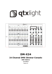
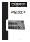
User Manual TABLE OF CONTENTS Table of Contents ................................................................................................................................................. 2 WHAT IS INCLUDED ................................................................................................................................................ 3 UNPACKING INSTRUCTIONS ..................................................................................................................................... 3 MANUAL CONVENTIONS .......................................................................................................................................... 3 ICONS .................................................................................................................................................................. 3 SAFETY INSTRUCTIONS ........................................................................................................................................... 4 FEATURES ............................................................................................................................................................ 4 ADDITIONAL FEATURES ........................................................................................................................................... 4 PRODUCT OVERVIEW (FRONT) ................................................................................................................................. 5 .......................................................................................................................................................................... 6 PRODUCT OVERVIEW (REAR PANEL) ......................................................................................................................... 6 COMMON TERMS ................................................................................................................................................... 8 3. Operating Instructions ...................................................................................................................................... 9 SETUP ................................................................................................................................................................. 9 Setting up the System ..................................................................................................................................... 9 Physical Fader Assignment (optional setup) ..................................................................................................... 9 Switching Between Page A and Page B (channels 1-24 and 25-48) .................................................................. 9 4. Programming .................................................................................................................................................. 10 ENTERING RECORD MODE (RECORD ENABLE) ......................................................................................................... 10 CREATE A SCENE ................................................................................................................................................ 10 EDIT ENABLE ...................................................................................................................................................... 10 ERASE A PROGRAM.............................................................................................................................................. 11 ERASE ALL SCENES ............................................................................................................................................. 11 RECORD CLEAR .................................................................................................................................................. 11 DELETE A STEP OR STEPS .................................................................................................................................... 12 INSERT A STEP OR STEPS ..................................................................................................................................... 12 MODIFY A STEP OR STEPS .................................................................................................................................... 12 5. Playback.......................................................................................................................................................... 13 PLAYING A SCENE................................................................................................................................................ 13 PLAYING A SCENE WITH AUDIO TRIGGERING ............................................................................................................ 13 PLAYING A SCENE WITH THE SPEED SLIDER ............................................................................................................. 13 PLAYING A SCENE WITH THE STANDARD BEAT .......................................................................................................... 14 CHANGE THE SPEED MODE BETWEEN 5 & 10 MINUTES ............................................................................................. 14 AUXILIARY CONTROLS .......................................................................................................................................... 14 MIDI OPERATION ................................................................................................................................................. 15 Setting MIDI IN.............................................................................................................................................. 15 Setting MIDI OUT .......................................................................................................................................... 15 Receiving MIDI File Dump ............................................................................................................................. 16 Sending MIDI File Dump................................................................................................................................ 16 6. Appendix ......................................................................................................................................................... 17 RETURNS PROCEDURE ......................................................................................................................................... 17 CLAIMS .............................................................................................................................................................. 17 CONTACT INFORMATION........................................................................................................................................ 17 TECHNICAL SPECIFICATIONS .................................................................................................................................. 18 Rev. 8 2 Stage Designer 50 1. BEFORE YOU BEGIN What is included 1 x Stage Designer™ 50 1 x DC 12 V, 500 mA output, 100~240 V, 50/60 Hz input auto-ranging power supply 1 x Manual 1 x Warranty Card • • • • Unpacking Instructions Immediately upon receiving a fixture, carefully unpack the carton, check the contents to ensure that all parts are present, and have been received in good condition. Notify the shipper immediately and retain packing material for inspection if any parts appear damaged from shipping or the carton itself shows signs of mishandling. Save the carton and all packing materials. In the event that a fixture must be returned to the factory, it is important that the fixture be returned in the original factory box and packing. Manual Conventions CHAUVET® manuals use the following conventions to differentiate certain types of information from the regular text. M EANING CONVENTION [10] <Menu> A DIP switch to be configured A key to be pressed on the fixture’s control panel 1~512 A range of values 50/60 A set of values of which only one can be chosen Settings MENU > Settings ON A menu option not to be modified (for example, showing the operating mode/current status) A sequence of menu options to be followed A value to be entered or selected Icons This manual uses the following icons to indicate information that requires special attention on the part of the user. M EANING ICONS This paragraph contains critical installation, configuration or operation information. Failure to comply with this information may render the fixture partially or completely inoperative, cause damage to the fixture or cause harm to the user. This paragraph contains important installation or configuration information. Failure to comply with this information may prevent the fixture from functioning correctly. This paragraph reminds you of useful, although not critical, information. Stage Designer 50 3 Rev. 8 Safety Instructions Please read these instructions carefully. It includes important information about the installation, usage and maintenance of this product. • • • • • • • • • Please keep this User Manual for future consultation. If you sell the unit to another user, be sure that they also receive this instruction booklet. Always make sure that you are connecting to the proper voltage and that the line voltage you are connecting to is not higher than that stated on decal or rear panel of the fixture. This product is intended for indoor use only! To prevent risk of fire or shock, do not expose fixture to rain or moisture. Make sure there are no flammable materials close to the unit while operating. In the event of serious operating problem, stop using the unit immediately. Never try to repair the unit by yourself. Repairs carried out by unskilled people can lead to damage or malfunction. Please contact the nearest authorized technical assistance center. Don’t connect the device to a dimmer pack. Make sure power cord is never crimped or damaged. Never disconnect power cord by pulling or tugging on the cord. Do not operate this device in more than 104° F (40° C) ambient temperature conditions. There are no user serviceable parts inside the unit. Do not open the housing or attempt any repairs yourself. In the unlikely event your unit may require service, please contact CHAUVET® at: 954-929-1115.2. Introduction The Stage Designer 50™ is a universal intelligent lighting controller. It allows the control of 48 channels with 96 scene/chase playback faders. Each scene/chase can contain up to 1000 individual steps, or looks. On the surface, when in the CHASE◄►SCENE mode, there are 12 physical faders for the playback of the saved programs. There are 4 pages of Scenes playback on Page A, and an additional 4 pages of playback faders on Page B. Programs can be triggered by music, midi, automatically or manually. Channel assignments can be reprogrammed for ease of controlling different fixtures. On the surface you will find various programming tools such as 24 channels fader, A/B master faders for cross mixing, and Fade and Speed time faders for on the fly adjustments. It also has an LED display for easy navigation of controls and menu functions. Features • • • • • • 48-channel DMX-512 dimming console 4 pages with 12 scenes each yields 48 total playback faders (simultaneous playback) 48,000 programmable steps 2 programmable aux buttons Adjustable chase and fade times Re-assignable channels Additional Features • • • • • • • • • Rev. 8 3-pin and 5-pin DMX connections Built-in cross fader, dark and kill buttons MIDI in, out and thru (with file dump) Direct audio input Sequential linking or simultaneous playback of chases Override chases on the fly Beat-activation, tap sync, auto run, midi in/out 6-space (6 U) rack mount Polarity selector 4 Stage Designer 50 Stage Designer 50 5 5 4 3 2 1 16 18 6 21 19 20 7 8 24 22 23 9 10 27 25 26 11 28 12 29 30 31 32 15 14 13 Product Overview (front) Rev. 8 Item Button or Fader Function 1 Channel Faders Indicates channels 1-12(25-36) 2 Channel Flash button Brings the relevant fader to 100% or DMX value of 255 3 Channel Faders Indicates channels 13-24(37-48) 4 Scene Playback indicators Indicates that the scene is playing back 5 Channel Flash button Brings the relevant fader to 100% or DMX value of 255 6 Down/Beat Rev Down functions to modify a scene in Edit mode, Beat Rev is used to reverse the chasing direction of a program with regular beat 7 Up/Chase Reverse Up function to modify a scene in Edit mode, Chase Reverse is used to reverse the chasing direction of a program under Speed Slider control. 8 LCD Display Shows the current activity or programming state 9 Delete/Rev One Delete a step in a scene or reverse he chasing direction of any program 10 Aux 1 Patchable; used to control a channel in 1 of 2 modes of operation 11 Insert/%or255 Insert is to add 1 step or steps into a scene; %or255 is used to change the display value cycle between % and 0-255 12 Aux 2 Patchable; used to control a channel in 1 of 2 modes of operation 13 Edit/All Rev Edit is used to activate Edit mode; All Rev is to reverse the chasing direction of all programs 14 Record/Shift Record is used to activate Record mode or program a step; Shift functions the alternate function of other buttons only 15 Audio/Page A_B Audio activate audio sync of chase; Page A_B switches the channel faders BETWEEN 1-24 MODE AND 25-48 MODE. Press and hold Record & Page A_B to switch between the 2 channel pages. 16 Blind Takes the channel out of a program temporarily in Chase◄►Scene mode 17 Chase Rev Reverses the direction of the chase playback 18 Dark Used to temporarily blackout overall output 19 Home Used to deactivate the Blind on a given channel 20 Park Used to select Single/Mix Chase, bring Channel 13-24(37-48) to full of current setting, or momentarily program a scene into Master B slider depending on the current mode. 21 Mode Select/Rec Speed Used to activate the operating mode; Rec Speed sets the speed of any programs chasing in Mix mode 22 Tap Sync Repeatedly tapping this button will establish the chase speed 23 Hold Used to momentarily maintain current scene 24 Page Tap to select pages of scenes from 1-4(Page A) and 1-4 (Page B) 25 Full On Momentarily bring all channels (1-48) to full intensity 26 Step Used to go to the next step when the Speed slider is set in Show Mode or in Edit mode. 27 Add Kill/Rec exit In Add mode, multiple scenes or Flash buttons will be on at the same time; In Kill mode, pressing any Flash button will kill any other scenes or programs; Rec Exit is used to exit from Program or Edit mode. 28 Blackout Used to kill all output, with exception of Full On. 29 Audio Level Fader Adjusts the audio sensitivity when in Audio trigger mode of scenes 30 Speed Fader Used to adjust the sped of scenes/chases running 31 Fade Fader Adjusts the fade-in, fade-out, and cross-fade times 32 Master A_B Adjusts overall intensity Product Overview (rear panel) Rev. 8 6 Stage Designer 50 1 2 3 4 5 6 7 8 9 Item Button or Fader Function 1 3-pin DMX output connector DMX control signal 2 5-pin DMX output connector DMX control signal 3 Polarity switch Used to select DMX polarity 4 MIDI Thru MIDI port for connecting to a sequencer or MIDI device 5 MIDI Out MIDI port for connecting to a sequencer or MIDI device 6 MIDI In MIDI port for connecting to a sequencer or MIDI device 7 Audio Input This jack accepts a line level audio input signal ranging from 100mV to 1Vpp 8 Remote Input Blackout and Full On may be controlled by a remote control using a standard ¼´jack 9 DC Input DC 12-20V, 500mAMin. Stage Designer 50 7 Rev. 8 Common Terms The following are common terms used in intelligent light programming. Rev. 8 Blackout is a state where all lighting fixtures’ light output are set to 0 or off, usually on a temporary basis. DMX-512 is an industry standard digital communication protocol used in entertainment lighting equipment. For more information read Sections “DMX Primer” and “DMX Control Mode” in the Appendix. Fixture refers to your lighting instrument or other device such as a fogger or dimmer which you can control. Programs are a number of scenes arranged one after another. It can be programmed as either a single scene or multiple scenes in sequence. Scenes are static lighting states. Sliders are also known as faders. Chases can also be called programs. A chase consists of a number of scenes arranged one after another. Scanner refers to a lighting instrument with a pan and tilt mirror; however DMX controllers can use this term to control any DMX-512 compatible device as a generic fixture. MIDI is a standard for representing musical information in a digital format. A MIDI input would provide external triggering of scenes using midi devices such as a midi keyboard. Stand Alone refers to a fixture’s ability to function independently of an external controller and usually in sync to music, due to a built in microphone. Fade slider is used to adjust the fade time between scenes within a chase. Speed slider affects the amount of time a scene will hold its state. It is also considered a wait time. Shutter is a mechanical device in the lighting fixture that allows you to block the lights path. It is often used to lessen the intensity of the light output and to strobe. Patching refers to the process of assigning faders to a DMX channel within a fixture. Playbacks can be either scenes or chases that are directly called to execution by the user. A playback can also be considered program memory that can be recalled during a show. 8 Stage Designer 50 3. OPERATING INSTRUCTIONS Setup Setting up the System 1. Place the Stage Designer 50™ on a level surface. Note! The Stage Designer 50™can also be rack mounted, occupying six rack spaces (6U). 2. Plug the AC to DC power supply into the system back panel and into the mains outlet. 3. Plug in your DMX cable(s) to your intelligent lighting as described in the respective fixture’s manual. For a quick overview of DMX see the “DMX Primer” on page 19. 4. Reset the system using the instructions on page 11 under ERASE ALL SCENES. Physical Fader Assignment (optional setup) Use this feature to combine or unify fixture control attributes for different fixtures. For example; if you were controlling 4 moving mirrors and 4 moving yokes, the color, gobo and dimmer channels may not line up ideally on the physical faders. Use this function to re-assign the dimmer, color and gobo channels to faders 1, 2 and 3. From now on you will be able to control the same attributes on all fixtures using the same fader location. This is also most useful when needing to combine all colors together. Action Notes All physical faders can be re-assigned to output on a different DMX channel. Faders are given a channel number and are labeled on the surface of the controller as such. 1. Press and hold RECORD button. 2. While holding the Record button, press the Flash button #6 (3) times. 3. Press the Flash button that you wish to assign the DMX channel output to. 4. While holding Record, press the Flash button corresponding to the DMX output that you wish to assign the Fader to. 5. Repeat steps 2 ~ 3 as often as necessary. Here is no limit to the amount of channels that can be assigned to a single fades. One can assign up to all 48 channels of DMX output to a single Fader. 6. Press and hold Record & Rec Exit to exit the mode. CHNO corresponds to the Physical Fader, while SLDNO corresponds to the DMX output channel. You can check to see what the assignment is by pressing the Fader button of the corresponding channel while in this mode. For example: you wish to assign Fader #1 to output to DMX channel #5. 1. Hold the Record button & press Fader#6 (3) times. 2. Press the Flash button #1. 3. While holding the Record button, press the Flash button #5. Switching Between Page A and Page B (channels 1-24 and 25-48) Action 1. Notes Press and hold Record & press Page A_B button. If you are on Page A, then this will bring you to Page B. If you are on Page B, then this will bring you to Page A. When the fixture turns on, it will revert to the previously used page. Page A is used to control channels 1-24, while Page B is used to control channels 25-48. The screen will display which current page. There’s an additional set of 4 pages of playback controls on Page B. Stage Designer 50 9 Rev. 8 4. PROGRAMMING Entering Record Mode (Record Enable) 1. 2. While holding the RECORD button, tap the Flash buttons 1-5-6-8 in sequence. Release the RECORD button. The Record LED lights up; Create a Scene A scene is a static lighting state. Scenes are stored in the temporary memory, until they are transferred to one of the playback faders. You may create a single scene or a succession of up to 999 steps per Scene. Action Notes Deselect Blackout if LED is lit. 1. Record enable. 2. Select the 1-24 Single mode by tapping the Mode Select button. This will give you control of all 24 channels of the first page. 3. Compose a look by moving the FADERS. (Changes in fixture attribute such as colors and gobos, or simply dimmer values). 4. Press Record to save the look into the temporary memory. 5. Repeat steps 2 ~ 4 until you have your desired scene. 6. Adjust the Speed and Fade sliders to achieve the desired amount of time a scene will be held in a chase (speed) and the amount of time allowed for the fixtures to move from one scene to the next (fade). 7. Select a Scene master to store your scene. Tap the Page button to select a page (1-4). 8. Press and hold the Record button & tap the Flash button for the scene that you wish to store it to. All LEDs will flash indicating the scene has been programmed into memory. 9. You can continue programming or exit. To exit program mode, press and hold the Record button & tap the Rec Exit button. Be sure that you are on the right page by viewing the screen where it displays Page A or Page B. This will enable 1-24 or 25-48 channel control. If you just wish to create a static look, then you must create a scene composed of only 1 step. There are 1000 steps available in every scene. Edit Enable Action Rev. 8 Notes 1. Record enable. 2. Use the Page button to select the page the program you wish to edit is on. 3. Tap the Mode Select button to select Chase◄►Scenes. 4. Press and hold the Edit button & tap the Flash button (13-24) of the Scene you wish to edit. 5. Release the Edit button. The relevant Scene Led should light, indicating you are in Edit mode. 10 When the EDIT mode is entered properly, the display will read EDITING. This mode is displayed here for only the initiation of EDIT mode. Please see the following sections on the uses of this mode in detail. Stage Designer 50 Erase a Program Action Notes 1. Record enable. 2. Use the Page button to select the page the Scene you wish to erase is on. 3. Press and hold the Edit button & tap the Flash button (13-24) twice of the Scene you wish to erase. 4. Release the 2 buttons. The LED for the corresponding program should light, indicating that it has been selected. 5. Press the Delete button. All LEDs should light, indicating the program is erased. Erase all Scenes Action Notes You must be in Record mode to Reset the controller. 1. Record enable 2. Press and hold RECORD. 3. While holding Record button, tap the flash buttons in the following sequence: 1-3-2-3. Release the Record button. 4. All LEDs should light, indicating all programs have been erased. 5. Press and hold RECORD & REC EXIT to exit the mode. The LED over the Record button will light, indicating the Record mode operation. Warning: this will reset the controller to its factory defaults. This will erase all programs and settings. Record Clear Action Notes All scenes stored in the temporary memory of the controller will be erased by this process. 1. Record enable. 2. Record a scene with 1 or more steps. 3. If you are not satisfied with the scene, you may press and hold the Record button & tap the Page/REC CLR button. All LEDs will flash, indicating the scenes have been cleared. Stage Designer 50 11 This process will not affect the scenes already programmed into a Scene fader. Rev. 8 Delete a Step or Steps Action Notes 1. Enter the EDIT enable. 2. Tap the Step button to scroll to the step you wish to delete. 3. Tap the Delete button when you reach the step you wish to delete. All LEDs will light, indicating the deletion of the step. 4. Repeat steps 2 and 3 until all of the unwanted steps have been deleted. 5. Press and hold the Record & Rec Exit button. The Scene button LED will turn off, indicating that the Edit mode has been exited. Insert a Step or Steps Action Notes 1. Record a scene or scenes you wish to insert. 2. Be sure you are in Chase◄►Scene and enter the Edit enable. 3. Tap the Step button to scroll to the step which you wish to insert the step before. You may read the step from the display. 4. Tap the Insert button to insert the step you’ve created before. 6. Exit Edit enable. Part of entering the Edit enable is selecting which scene you wish to Edit. See section on Edit enable for further instructions. All LEDs will flash to indicate a successful Insert of the step. Modify a Step or Steps Action Rev. 8 Notes 1. Edit enable. 2. Press and hold the Up button if you want to raise the intensity. Press the Down button if you want to lower the intensity. 3. Tap the Step button to scroll to the step which you wish to insert the step before. You may read the step from the display. 4. While holding the Up or Down button, tap the Flash button corresponding to the DMX channel of the Scene you wish to modify until you reach the desired intensity value read from the display. Then, you may tap the Flash buttons until you are satisfied with the new Scene. 5. Repeat steps 2, 3, and 4 until all the steps have been modified. 6. Exit EDIT enable. 12 Part of entering the Edit enable is selecting which scene you wish to Edit. See section on Edit enable for further instructions. All LEDs will flash to indicate a successful Insert of the step. Stage Designer 50 5. PLAYBACK This controller uses the Channel Faders and Channel Flash buttons for multiple uses. In this occurrence, Channel Faders 13-24 (37-48) are used for the playing back of Scenes already recorded. This is only when the controller is in the Chase◄►Scene mode. In this instance, Master Fader A will control the manual fader controls, while Master Fader B will control the Scenes being played back. Playing a Scene A Scene can contain up to 1,000 steps. The term steps and scenes are used interchangeably in this manual. Action Notes 1. Tap the Mode Select button to select Chase◄►Scene mode. 2. Tap the Page button to select the correct page the program you wish to run is located. 3. Push master Slider B to its maximum position (fully down). 4. Move the desired Channel slider (1324) to its maximum, and the Scene will fade in depending upon current fade time. 5. Move the channel slider to adjust the output of the current program. The current mode is indicated by the 3 LEDs. Red is the Chase◄►Scene. Yellow is 2-scene preset A/B. And, Green is 1-24 single mode. You may press and hold down the relevant Flash button for the Scene to trigger the button momentarily. Playing a Scene with Audio Triggering Action Notes 1. Select your Scene as described in the above section. 2. Tap the Audio button until its LED lights, indicating AUDIO mode is active. 3. Use the Audio Level slider to adjust the sensitivity. 4. To return to normal mode, tap the Audio button a second time, causing its LED to go out. AUDIO mode is disengaged. This is the process of using the built-in microphone, or using the audio jack located on the rear of the controller to use an alternative audio source for triggering of the Scenes. Playing a Scene with the Speed Slider Action Stage Designer 50 Notes 1. Select your Scene as described in the above sections. 2. Move the Speed slider to SHOW MODE position (fully down). 3. Press and hold the Rec Speed button & tap the corresponding Flash button (13-24). The Scene tapped will no longer run with the standard beat. 4. Now, you may move the Speed slider to select your desired speed. 13 Be sure AUDIO mode is disengaged. Step #3 is not necessary if the selected Scene is not recorded with the Standard beat. Rev. 8 Playing a Scene with the Standard Beat Action Notes 1. Tap the Mode select button to select Chase◄►Scene mode. 2. Tap the Park button to select Mix Chase mode. The LED lights, indicating the selection. 3. Select your Scene as described in the previous sections. 4. Move the Speed slider until the display reads your desired value. 5. Press and hold Rec Speed button & tap the Flash button (13-24) to store the Scene. The Scene will now run with the set time or beat when engaged. 6. Repeat steps 4 & 5 to set a new beat time. Be sure AUDIO mode is disengaged. As an alternative to using the Speed slider to input the speed, you may use the Tapsync button (2) times to define your beat. Change the Speed Mode Between 5 & 10 Minutes Action Notes 1. Press and hold the Record button. 2. Tap the Flash button 5 or 10 three times while holding down the Record button. 3. The 5min or 10min LED should light, indicating the Speed the slider is set to run. Auxiliary Controls This is the process of assigning the Auxiliary controls. These will act as shortcuts and are most commonly used for DMX strobe lights or DMX fog machines. However, they are not limited to these functions, such as Pan/tilt control-very useful for remote followspot controls. Action Rev. 8 Notes 1. Press & hold RECORD & tap the Flash button 7 or 8 (3) times. The display should indicate activation of the mode. 2. There are 3 functions. FUNC 1 states that the Auxiliary control is not assigned to any channel. FUNC 2 refers o the auxiliary controls working much like the channel fader along with the flash buttons. FUNC 3 is somewhat different. The rotary knob acts to set the total output of the flash button below it. 3. While holding down the RECORD button, select the function you wish for the auxiliary control by pressing Flash button 1, 2, or 3. Release the buttons. 4. To assign the auxiliary to a channel, press the Flash button for the channel you wish to assign the auxiliary control to. This sets the channel assignment. The corresponding Led above the channel will light, indicating that the channel has ben assigned. 5. Record exit. 14 You may refer to the display for the functions being edited. Press 7 (3) times for AUX 1 patching, and 8 (3) times for AUX 2 patching. While assigning an auxiliary to mode 2, the Fader for that channel will not function. It will act as moving the channel. While assigning an auxiliary to mode 3, the channel fader and the auxiliary controls will both work for that channel on an HTP (highest takes precedent) operating principle. Stage Designer 50 Midi Operation The controller will only respond to MIDI commands on the MIDI channel that it is assigned to. All MIDI control is performed using Note on commands. All other MIDI instructions are ignored. To stop a chase, send the blackout on note. Setting MIDI IN Action Notes 1. While holding down the RECORD button, simultaneously tap Flash button #1 three times. The display reads MIDI CHANNEL IN to indicate channel setup is available. 2. Select the MIDI control channel (1~16) by tapping Flash buttons 1~16. The relevant channel LED lights indicating MIDI IN channel is set. 3. While holding down RECORD, tap the REC EXIT button to exit MIDI setting. MIDI NOTE This is the Channel that the controller will receive MIDI note commands. FUNCTION (TURN ON/OFF) 22-69 Trigger scenes 1-48 (100%) 70-117 Activate Channel 1-48 118 FULL-ON 119 DARK (momentary blackout) 120 HOLD 121 Turn on or off AUDIO 122 MODE: CHASE◄ ►SCENE 123 MODE: 1-12A_1-12B 124 MODE: 1-24A 125 Step 126 BLACKOUT 127 Channel page (1~24, 25~48) Setting MIDI OUT Action 1. Notes While holding down the RECORD button, simultaneously tap Flash button #2 three times. The display reads MIDI CHANNEL OUT to indicate channel setup is available. 2. Select the MIDI control channel (1~16) by tapping Flash buttons 1~16. The relevant channel LED lights indicating MIDI OUT channel is set. 3. While holding down RECORD, tap the REC EXIT button to exit MIDI setting. Stage Designer 50 15 This is the Channel that the controller will transmit MIDI note commands. Rev. 8 Receiving MIDI File Dump Action 1. 2. Notes While holding down the RECORD button, simultaneously tap Flash button #3 three times. The display reads MIDI FILEDUMP RECVING 000% when the device is in the correct mode. While holding down RECORD, tap the REC EXIT button to exit MIDI setting. This is the process of copying your entire show to another STAGE DESIGNER™ 50. This will not work with any other device. This process can take several minutes to complete. The controller will automatically begin sending the FILE DUMP once the mode has been selected. Therefore, be sure that the other device has previously been setup to receive the transfer. During FILE DUMP, all other operations will cease to function. If errors or power failure occurs, FILE DUMP will be interrupted and stop. Sending MIDI File Dump Action 1. 2. Notes While holding down the RECORD button, simultaneously tap Flash button #4 three times. The display reads MIDI FILEDUMP SENDING 000% when the device is in the correct mode. While holding down RECORD, tap the REC EXIT button to exit MIDI setting. This is the process of copying your entire show to another STAGE DESIGNER™ 50. This will not work with any other device. This process can take several minutes to complete. The controller will automatically begin sending the FILE DUMP once the mode has been selected. Therefore, be sure that the other device has previously been setup to receive the transfer. During FILE DUMP, all other operations will cease to function. If errors or power failure occurs, FILE DUMP will be interrupted and stop. Rev. 8 16 Stage Designer 50 6. APPENDIX Returns Procedure Returned merchandise must be sent prepaid and in the original packing, call tags will not be issued. Package must be clearly labeled with a Return Merchandise Authorization Number (RMA #). Products returned without an RMA # will be refused. Call CHAUVET® and request RMA # prior to shipping the fixture. Be prepared to provide the model number, serial number and a brief description of the cause for the return. Be sure to properly pack fixture, any shipping damage resulting from inadequate packaging is the customer’s responsibility. CHAUVET® reserves the right to use its own discretion to repair or replace product(s). As a suggestion, proper UPS packing or double-boxing is always a safe method to use. Note: If you are given an RMA #, please include the following information on a piece of paper inside the box: 1. 2. 3. 4. 5. Your name Your address Your phone number The RMA # A brief description of the cause for the return Claims Damage incurred in shipping is the responsibility of the shipper; therefore the damage must be reported to the carrier upon receipt of merchandise. It is the customer's responsibility to notify and submit claims with the shipper in the event that a fixture is damaged due to shipping. Any other claim for items such as missing component/part, damage not related to shipping, and concealed damage, must be made within seven (7) days of receiving merchandise. Contact Information World Headquarters United Kingdom & Ireland CHAUVET® CHAUVET® Europe Ltd. General Information Address: Voice: Fax: Toll free: Technical Support Voice: Fax: Email: 5200 NW 108th Avenue Sunrise, FL 33351 (954) 929-1115 (954) 929-5560 (800) 762-1084 (954) 929-1115 (Press 4) (954) 756-8015 [email protected] World Wide Web Address: Voice: Fax: Unit 1C Brookhill Road Industrial Estate Pinxton, Nottingham, UK NG16 6NT +44 (0)1773 511115 +44 (0)1773 511110 Technical Support Email: [email protected] World Wide Web www.chauvetlighting.com Stage Designer 50 General Information 17 www.chauvetlighting.co.uk Rev. 8 Technical Specifications WEIGHT & DIMENSIONS Length ............................................................................................................................................................... 19 in (483 mm) Width.............................................................................................................................................................. 10.5 in (267 mm) Height ................................................................................................................................................................ 3.5 in (89 mm) Weight ............................................................................................................................................................ 10.3 lbs (4.7 kg) POWER Supplied Voltage Adapter ............................................................................................................................ DC 12 V, 500 mA Adapter (100~240 VAC, 50/60 Hz) ..................................................................................................................... 2-pin Edison Internal fuse....................................................................................................................................................... F 0.5 A, 250 V THERMAL Maximum ambient temperature ........................................................................................................................ 104° F (40° C) CONTROL & PROGRAMMING 3-pin DMX: Data output ........................................................................................................................... locking 3-pin XLR female socket Data pin configuration ..............................................................................................................pin 1 shield, pin 2 (-), pin 3 (+) Protocols.........................................................................................................................................................DMX-512 USITT 5-pin DMX: Data output ........................................................................................................................... locking 5-pin XLR female socket Data pin configuration ............................................................................ pin 1 shield, pin 2 (-), pin 3 (+), pins 4+5 (not used) Protocols.........................................................................................................................................................DMX-512 USITT ORDERING INFORMATION Stage Designer™ 50 ............................................................................................................................. STAGEDESIGNER50 WARRANTY INFORMATION Warranty .............................................................................................................................................. 2-year limited warranty Rev. 8 18 Stage Designer 50