1
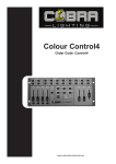
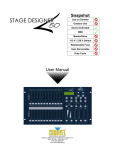
Colour Control24
Order Code: Control24
www.cobrainternational.com
User Manual
COBRA Colour Control 24
Dear Customer,
Thank you for purchasing the COBRA Colour Control 24. Cobra is one of the leading manufacturers of
professional equipment and has decades of experience in design and production.
To meet all your requirements, this unit has been designed and built to the highest of standards so you can
be assured you have made a good investment.
Please read this manual fully for your safety and to take full advantage of the COBRA Colour Control 24
features.
Product Description:
The COBRA Colour Control 24 is a 48-channel DMX controller suitable for dimmer packs, LED lights and effect
lights. You can store up to 96 scenes/chases, with each chase having a maximum of 1000 steps.
This desk can be used as a 48 control desk or a 24 in double pre-set mode.
Channel sliders can be patched to any DMX address from 1-48.
General Advice:
1. Read manual completely before using this product.
2. Keep manual for future reference.
3. Carry and transport this product with care as hard knocks or dropping it may result in mechanical or
electrical damage.
4. The manufacturer takes no responsibility for injury or damage caused by not following the manual
provided.
Protection from Electric Shock:
1. Do not connect the AC power plug to the unit before connecting your lights.
2. Only connect this unit to a mains socket with suitable trip protection and RCD protection.
3. Never pull the mains cable to disconnect from the mains socket – always pull by the mains plug.
4. Always disconnect the unit from the mains before cleaning. Cleaning should be carried out with a soft
dry cloth.
5. Do not expose this unit to any liquids. Do not operate near exposed water or high humidity.
6. Choose a suitable route for mains cables, ensuring the mains lead is not a trip hazard or at risk from
being crushed.
7. Do not open the unit to service. There are no user serviceable parts inside the unit and this will void
your warranty.
2
Protection from Fire:
1. Do not place near sources of heat.
2. Do not block any ventilation holes.
3. Check your AC wall socket will take the load you are applying to avoid any overloading.
4. Make sure you are using the correct voltage DC power supply, set to the correct polarity.
Protection from Injury & Damage:
1. Never try to modify this unit.
2. Always install the unit in a suitable location where vibrations to the unit are avoided.
3. Check the unit matches the mains voltage and frequency before plugging it in to your mains socket.
4. If any liquids or objects have entered the unit, switch it off immediately and consult a qualified
engineer.
5. If the unit malfunctions or there is any damage to the mains cable, disconnect immediately and consult
a qualified engineer.
6. All parts should be replaced with genuine spare parts and carried out by a qualified engineer.
Unpacking:
1. The box should contain Colour Control 24, DC power supply and user manual.
2. If there is any damage or missing parts, please contact your dealer immediately.
Specifications:
Name:
Code:
Power Supply:
Power Consumption:
Output:
Audio Input:
Dimensions:
Weight:
Colour Control 24.
Control 24.
DC 12v 500mA min.
20 watts.
DMX 512 (3-pin & 5-pin XLR)
100mV ~ 1Vpp
483 x 264 x 100mm
4.7kg
Features:
The Colour Control 24 is a DMX 48-channel controller suitable for dimmer packs, LED lights and effects lights.
Features Include:
1. Controls up to 48 channels (24 on page A, 24 on page B).
2. 96 scenes/chases can be stored.
3. Speed and fade can be used after programming.
4. Controller can be used in 24-channel double pre-set mode.
5. Chases and scenes can be mixed in playback.
6. A chase can have up to 1000 steps.
7. 5-pin & 3-pin output sockets.
8. 19” rack mountable (6u).
9. Channel sliders can be assigned to different DMX addresses.
10. 2 AUX switches/knobs for DMX foggers or strobes. These can be assigned to any DMX address between 1 & 48.
**Note: A knowledge of DMX is required to fully use this controller**
3
1
2
3
4
5
6
7
15
9
10
12
26
29
8
27
28
14
16
18
25
31
30
19
20
13
11
17
33
35
32
34
22
21
24
23
36
37
Fig 1
4
Controller Front:
1. Channel Fader Indicators. Indicates 1-12 page A, 25-36 page B.
2. Channel Fader. Used to adjust the intensity of the channels 1-12 (25-36)
3. Channel Flash Button. Brings the relevant fader to 100% or DMX value to 255.
4. Channel Fader Indicators. Indicates channels 13-24 page A, 37-48 page B.
5. Scene Playback Indicators. Indicates that the playback is active.
6. Channel Fader. Used to adjust the intensity of the channels 13-24 (37-48).
7. Channel Flash Button. Brings the relevant fader to 100% or DMX value to 255.
8. Dark. Used to temporarily blackout overall output.
9. LCD Display. Shows the current activity or programming state.
10. Down/Beat Rev. Down functions to modify a scene in Edit mode. Beat Rev is used to reverse the chase
direction of a program with a regular beat.
11. Mode Select/Rec Speed. Used to activate the operating mode; Rec Speed sets the sets the speed of any
programs chasing in Mix mode.
12. Up/Chase Reverse. Up function to modify a scene in Edit mode. Chase Reverse is used to reverse the
chase direction of a program under Speed Slider control.
13. Page. Tap to select pages of scenes from 1-4 page A & 1-4 page B.
14. Delete/Rev One. Delete a step in a scene or reverse one chasing direction of any program.
15/16. AUX1. Used to control a channel. Patchable to different DMX addresses.
17/18. AUX2. Used to control a channel. Patchable to different DMX addresses.
19. Edit/All Rev. Edit is used to activate Edit mode; All Rev is to reverse the chasing direction of
all programs.
20. Insert % or 0-255. Insert is to add steps into a scene; % or 0-255 is used to change
the display value cycle between % and 0-255.
21. Record/Shift. Record is used to activate Record mode or program a step; Shift functions the
alternate functions of other buttons only.
22. Add Kill/Rec Exit. In Add mode, multiple scenes or Flash buttons will be on at the same time;
In Kill mode, pressing any Flash button will kill any other scenes or programs; Rec Exit is used
to exit from Program or Edit mode.
23. Audio/Page A_B. Audio activates audio sync of chase; Page A_B switches the channel faders
between 1-24 mode and 25-48 mode. Press and hold Record and Page A_B to switch
between the 2 channel pages.
24. Step. Used to go to the next step when the Speed slider is set on Show mode or Edit mode.
25. Hold. Used to momentarily maintain current step in a program.
26. Master A Button. Brings channel 1-24 to full when slider A is at minimum.
27. Master A. Adjusts overall intensity.
28. Blind. Takes a channel out of a program temporarily in Chase <> Scene mode.
29. Park. Used to select Single/Mix Chase, bring Channel 1-24 (37-48) to full of current setting.
30. Home. Used to deactivate the Blind on a given channel.
31. Master B. adjusts overall intensity.
32. Tap Sync. Repeatedly tapping this button will establish the chase speed.
33. Fade Fader. Adjusts the fade-in, fade-out and cross-fade times.
34. Full On. Momentarily brings all channels (1-48) to full intensity.
35. Blackout. Used to kill all output, with exception of Full On.
36. Speed Fader. Used to adjust the speed of scenes/chases running.
37. Audio Level Fader. Adjusts the audio sensitivity when in Audio trigger mode of scenes.
38
39
40
41
42
43 44 45
46
Fig 2
Controller Rear:
38. 3-pin DMX OUT.
39. 5-pin DMX OUT.
40. Polarity Switch.
41. Midi Thru.
42. Midi Out.
43. Midi In.
44. Audio Input. This RCA accepts a fine level audio input signal ranged from 100mV to 1Vpp.
45. Remote Input. Blackout and full can be controlled by a remote control with a ¼ inch jack stereo
connection.
46. DC Input. Connect a 12dc, 500mA min. adaptor.
Common Terms:
The following are common terms used in intelligent light programming
• Blackout is a state where all lighting fixtures light output are set to 0 or off, usually on a temporary basis.
• DMX-512 is an industry standard digital communication protocol used in entertainment lighting
equipment.
5
• Fixture refers to your lighting effect or other device such as a fogger or dimmer which you can control.
• Sliders are also known as faders.
• Scanner refers to a lighting effect with a pan and tilt mirror; however DMX controllers can use this term
to control any DMX-512 compatible device as a generic fixture.
• MIDI is a standard term for representing musical information in a digital format. A MIDI input would
provide external triggering of scenes using MIDI devices such as a MIDI keyboard.
• Stand Alone refers to a fixture’s ability to function independently of an external controller and usually in
sync to music due to a built-in microphone.
• Fade slider is used to adjust the fade time between scenes within a chase.
• Speed slider affects the amount of time a scene will hold its state. It is also considered a wait time.
• Shutter is a mechanical device in the lighting fixture that allows you to block the light’s path. It is often
used to lessen the intensity of the light output and to strobe.
• Patching refers to the process of assigning faders to a DMX channel within a fixture.
• Playbacks can be either scenes or chases that are directly recalled by the user. A playback can also
be considered program memory that can be used during a show.
First Time Operation:
1. Remove all packaging materials.
2. Connect a DMX cable from controller to your first light/pack. Connect a DMX cable from first light/pack
to second. Do this until all lights or packs are connected.
3. Plug any par can/theatre spots in to your dimmer packs if you are using dimmer packs.
4. Plug your controller in to the mains with the supplied AC/DC power supply.
5. Plug your dimmer packs or lights in to the mains.
6. If you are using 4-channel packs or 4-channel LED par cans, set the first unit to DMX address 1, the
second to DMX address 5, third to DMX address 9 and fourth to DMX address 13. (Some lights/packs
will have digital display; some will have small dip switches.
7. Once you have turned on your controller if the black light is lit, press the black button.
8. Move the fade slider to the top.
9. Move Master A to the top and B to the bottom.
10. Using the Mode Select button put the controller in 1-24 single pre-set mode.
11. Move all the channels sliders up and your lights should light up. If they don’t, switch the polarity switch
on the back of the controller.
12. Follow the rest of the manual for all your programming options.
Switching Between Page A & Page B (Channels 1-24 & 25-48):
1. Press and hold Record & press Audio/Page A_B button. If you are on Page A, this will bring you to Page B.
If you are on Page B then this will bring you to Page A.
6
Notes:
When the fixture turns on, it will revert to the previously used page.
Page A is used to control channels 1-24, while Page B is used to control channels 25-48.
The screen will display the current page.
There are an additional set of 4 pages of playback controls on Page B.
You can't mix scenes/chases where one is stored on Page A and one is stored on Page B.
Entering Program Mode (Record Enable):
1. While holding the Record button, tap the Flash buttons #1-5-6-8 in sequence.
2. Release the Record button. The record LED lights up.
Exiting Program Mode:
1. Hold Record/Shift button. Whilst holding, press the Add Kill/Rec Exit button.
Create a Scene/Chase:
1. Record enable.
2. Select the 1-24 Single mode by tapping the Mode Select button. This will give you control of all 24
channels on the first page.
3. Compose a look by moving the faders (changes in fixture attribute such as colours & gobos, or simply
dimmer values).
4. Press Record to save the look in to the temporary memory.
5. Repeat steps 2-4 until you have your desired chase.
6. Do not repeat steps 2-4 if you are only saving a scene.
7. Select a scene master to store your scene. Tap the Page button to select a Page (1-4)
8. Press and hold the Record button and tap the Flash button for the scene that you wish to store it to. All
LEDs will flash indicating the scene has been programmed in to memory..
9. You can continue programming or exit. To exit programme mode, press and hold the Record button and
tap the Rec Exit button, the record LED will turn off.
Notes:
Deselect Blackout if LED is lit.
Be sure that you are on the right page by viewing the screen where it displays Page A or Page B. This will
enable 1-24 or 25-48 channel control.
If you just wish to create a static look, then you must create a scene composed of only 1 step.
There are 1000 steps available in every chase.
Edit Enable:
1. Record enable.
2. Use the Page button to select the page the program you wish to edit is on.
3. Tap the Mode Select buttons to select Chase <> Scenes.
4. Press and hold the Edit button and tap the Flash Button (13-24) of the scene/chase you wish to edit.
5. Release the Edit button. The relevant scene LED should light indicating you are in edit mode.
Notes:
When the edit mode is entered properly, the display will read editing.
This mode is displayed here for only the initiation of edit mode. Please see the following sections on the uses
of this mode in detail.
Delete a Step or Steps:
1. Enter the edit mode.
2. Tap the Step button to scroll to the step you wish to delete.
3. Tap the Delete/Rev One button when you reach the step you wish to delete. All the LEDs will light,
indicating the deletion of the step.
4. Repeat steps 2 & 3 until all of the unwanted steps have been deleted.
5. Press and hold the Record & Rec Exit Button. The scene button LED will turn off, indicating that the edit
mode has been exited.
Insert Step or Steps:
1. Record a scene you wish to insert (now your scene is stored in the edit buffer).
2. Be sure you are in Chase <> Scene and enter the edit mode.
7
3.
4.
5.
Tap the Step button to scroll to the position of which you wish to insert your new step.
Tap the Insert button to insert the step you’ve created before.
Exit the edit mode.
Notes:
Part of entering the edit mode is selecting which scene you wish to edit. See selection on edit enable for
further instructions.
All LEDs will flash to indicate a successful insert of the step.
Modify a Step or Steps:
1. Enter the edit mode.
2. Tap the Step button to scroll to the step which you want to edit.
3. Whilst holding the Up or Down button, tap the Flash button corresponding to the DMX channel of the
scene you wish to modify until you reach the desired intensity value read from the display. Then you
may tap the Flash buttons until you are satisfied with the new Scene.
4. Repeat steps 2, 3 and 4 until all the steps have been modified.
5. Exit edit mode.
Notes:
Part of entering the edit mode is selecting which scene you wish to edit. See section on edit enable for further
instructions.
All LEDs will flash to indicate a successful insert of the step.
Erase a Scene or Chase:
1. Record enable.
2. Use the Page button to select the page that the scene you wish to erase is on.
3. Press and hold the Edit button and tap the Flash Button (13-24) of the Scene you wish to erase twice.
4. Release the 2 buttons. All LEDs should light indicating the program is erased.
Erase all Scenes/Chases:
1. Record enable.
2. Press and hold Record.
3. While holding the Record button, tap the Flash buttons in the following sequence #1-3-2-3. Release the
Record button.
4. All LEDs should light, indicating all programs have been erased.
5. Press and hold Record & Rec Exit to exit the mode.
Notes:
You must be in record mode to reset the controller.
The LED over the record button will light, indicating the record mode is in operation.
**Warning: This will reset the controller to its factory defaults. This will erase all programs and settings**
Record Clear:
1. Record enable.
2. Record a scene with one or more steps.
3. If you are not satisfied with the scene, you may press and hold the Record button and tap the Page
button. All LEDs will flash, indicating the scenes have been cleared.
Notes:
All the scenes stored in the temporary memory of the controller will be erased by this process.
This process will not affect the scenes already programmed in a scene fader.
8
Playback:
This controller uses the Channel Faders and Channel Flash buttons for multiple uses. In this instance, Channel
Faders 13-24 (37-48) are used for the playing back of Scenes/Chases already recorded. This is only when the
controller is in the Chase <> Scene mode. In this instance, Master Fader A will control the manual fader
controls, while Master Fader B will control the Scenes being played back.
Playing a Scene/ Chase:
1. Press the Mode Select button to select Chase <> Scene mode.
2. Press the Page button to select the correct page that the scene you wish to run is located.
3. Push the Master Fader B in to its maximum position (fully down).
4. Move the desired Channel fader (13-24) to its maximum, and the scene will fade in depending upon
current fade time.
5. Move the Channel fader to adjust the output of the current program.
Notes:
The current mode is indicated by the 3 LEDS:
Red is the Chase <> Scene.
Yellow is 2-scene pre-set A/B.
Green is 1-24 single mode.
You may press and hold down the relevant flash button for the scene to trigger to scene/chase momentarily.
Playing a Scene/Chase by Audiotriggering:
1. Select your scene/chase as described in the above section.
2. Press the Audio button until its LED lights, indicating the audio mode is active.
3. Use the Audio Level fader to adjust the sensitivity.
4. To return to normal mode tap the Audio button a second time causing its LED to go out. Audio mode is
disengaged.
Notes:
This is the process of using the built-in microphone, or using the audio jack located on the rear of the
controller to use an alternative audio source for triggering the scenes/chases.
Playing a Scene/Chase using the Speed Fader:
1. Select a saved scene/chase.
2. Move the Speed fader to the desired position (the top being the fastest).
3. Now you may move the Speed fader to select your desired speed.
Notes:
Be sure audio mode is disengaged.
Fade time can be used as well.
Change the Speed Mode Between 5 & 10 Minutes:
1. Press & hold the Record button.
2. Tap the Flash button #5 or #10 three times, whilst holding down the Record button.
3. The 5 min or 10 min LED should light, indicating the Speed the fader is set to run.
Physical Fader Assignment:
Use this feature to combine or unify fixture control attributes for different fixtures. For example; if you were
controlling 4 moving mirrors and 4 moving yokes, the colour, gobo and dimmer channels may not line up
ideally on the physical faders. Use this function to re-assign the dimmer, colour & gobo channels to faders 1,
2 & 3. From now on you will be able to control the same attributes on all fixtures using the same fade
location. This is also useful when needing to combine all colours together.
1.
2.
3.
Press and hold the Record button.
While holding the record button, press the Flash button #6 three times.
Press the flash button that you wish to assign the DMX channel output to.
9
4.
5.
6.
1.
2.
3.
Whilst holding Record, press the flash button corresponding to the DMX output that you wish to assign
the fader to.
Repeat steps 2-3 as often as necessary.
Press and hold Rec and push Rec Exit.
EXAMPLE: You wish to assign fader #1 to output of DMX channel #5.
Hold the record button and press Flash button #6 three times.
Press Flash button #1.
While holding the Record button, press the Flash button #5.
Notes:
All physical faders can be reassigned to output on a different DMX channel. Faders are given a channel
number and are labled on the surface of the controller as such.
You can check to see what the assignment is by pressing the fader button of the corresponding channel while
in this mode.
There is no limit to the amount of channels that can be assigned to single fades. One can assign up to all 48
channels of DMX output to a single fader.
Auxiliary Controls:
This is the process of assigning the Auxiliary controls. These will act as shortcuts and are most commonly
used for DMX strobe lights or DMX fog machines. However they are not limited to these functions and can be
used for Pan/Tilt control. This is very useful for remote follow spot controls.
1.
2.
3.
4.
5.
Press and hold Record and tap the Flash button #7 or #8 three times. This display should indicate
activation of the mode. (Flash button #7 is for AUX1 and Flash button #8 is for AUX2).
There are 3 functions:
FUNC 1 states that the auxiliary control is off.
FUNC 2 refers to the auxiliary controls. They work the same as the channel fader does with fader control
with knob and flash control with button.
FUNC 3 AUX is set to latch. The rotary knob controls the intensity and will only work when the flash
button is pressed.
Whilst holding down the Record button, select the function you wish for the auxiliary by pressing Flash
button #1, #2 or #3. Release the buttons.
To assign the auxiliary to a channel, press the Flash button for the channel you wish to assign the
auxiliary control to. This sets the channel assignment. The corresponding LED above the channel will
light, indicating that the channel has been assigned.
Press Record and tap Rec Exit buttons to exit this mode.
Notes:
You may refer to display for the functions being edited.
Press #7 three times for AUX1 patching and #8 three times for AUX2 patching.
While assigning an auxiliary to mode 2, the fader for that channel will not function. It will act as moving the
channel.
While assigning on auxiliary to mode 3, the channel fader and the auxiliary controls will both work for that
channel on an HTP (highest takes precedent) operating principle.
MIDI Operation:
The controller will only respond the MIDI commands on the MIDI channel that it is assigned to. All MIDI
control is performed using Note on commands. All other MIDI instructions are ignored. To stop a chase, send
the Blackout On note.
10
Setting MIDI IN:
1. Whilst holding down the Record button, simultaneously tap the Flash button #1 three times. The display
reads MIDI CHANNEL IN to indicate the channel setup is available.
2. Select the MIDI control channel (1-16) by tapping Flash buttons #1-16. The relevant channel LED light
indicating MIDI IN channel is set.
3. Whilst holding down record, tap the Rec Exit button to exit MIDI settings.
Note:
This is the channel that the controller will receive MIDI note command.
MIDI note
Function (TURN ON/OFF)
27-69
Turn on or off program 1-48
94
FULL-ON
79-93
95
96
97
98
99
100
101
102
Activate channel 1-24
DARK (momentary blackout)
HOLD
Turn on or off AUDIO
NODE: CHASE <> SCENE
MODE: 1-12A_1-12B
MODE: 1-24A
Step
BLACKOUT
Note:
When working with MIDI notes 22-93, you may simulate a fader’s increase and decrease by adjusting the
velocity of the note.
Setting MIDI OUT:
1. Whilst holding down the Record button, simultaneously tap the Flash button #2 three times. The display
reads MIDI CHANNEL OUT to indicate channel setup is available.
2. Select the MIDI control (1-16) by tapping Flash buttons #1-16. The relevant channel LED lights indicating
MIDI OUT channel is set.
3. Whilst holding down Record, tap the Rec Exit button to exit MIDI setting.
Note:
This is the channel that the controller will transmit MIDI note commands.
Receiving MIDI File Dump:
1. Whilst holding down the Record button, simultaneously tap the flash button #3 three times. The display
reads MIDI FILEDUMP RECEIVING 000% when the device is in the correct mode.
2. When holding down Record, tap the Rec Exit button to exit the MIDI setting.
Notes:
This is the process of copying your entire show to another Colour Controller. This will not work with any other
device.
This process can take several minutes to complete.
The controller will automatically begin sending the FILE DUMP once the mode has been selected. Therefore
be sure that the other device has previously been set up to receive the transfer.
During FILE DUMP, all other operations will cease to function.
If error or power failure occurs, FILE DUMP will be interrupted and stop.
Sending MIDI File Dump:
1. Whilst holding down the Record button, simultaneously tap the Flash button #3 four times. The display
will read MIDI FILEDUMP SENDING 000% when the device is in the correct mode.
2. When holding down Record, tap the Rec Exit button to exit the MIDI setting.
11
Notes:
This is the process of copying your entire show to another Colour Controller. This will not work with any other
device.
This process can take several minutes to complete.
The controller will automatically begin sending the FILE DUMP once the mode has been selected. Therefore
be sure that the other device has previously been set up to accept the transfer.
During FILE DUMP all other operations will cease to function.
If errors or power failure occurs, FILE DUMP will be interrupted and stop.
Maintenance:
The COBRA Colour Control 24 requires almost no maintenance. However you should keep the unit clean.
Disconnect the mains power supply and then wipe the cover with a dry cloth. Do not immerse in liquid. Do
not use alcohol or solvents.
Keep connections clean. Disconnect electric power and then wipe the DMX and audio connections with a
dry cloth.
Troubleshooting:
If fixture is not responding to DMX:
1. Check all connections are correct.
2. Check DMX addressing is correct.
3. Check blackout is turned off.
4. Check polarity switch at the back of the unit is in the correct position.
5. Check fade slider is up to the top.
6. Check Master A is at the top and B is to the bottom.
7. If all the above doesn’t work, unplug from the mains, wait 30 seconds then plug back in.
8. If it is still not working, contact your dealer.
12