1
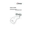
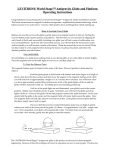
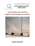
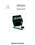
Specialty Plants Specialty Experiment: PIV-plus-Feedforward Control Magnetic Levitation (MagLev) Student Handout Magnetic Levitation Control Laboratory – Student Handout Table of Contents 1. Objectives............................................................................................................................1 2. Prerequisites.........................................................................................................................2 3. References............................................................................................................................2 4. Experimental Setup..............................................................................................................2 4.1. Main Components........................................................................................................2 4.2. Wiring..........................................................................................................................3 5. Controller Design Specifications.........................................................................................3 5.1. Coil Current Controller Specifications........................................................................3 5.2. Ball Position Controller Specifications........................................................................3 6. Pre-Lab Assignments...........................................................................................................5 6.1. MagLev System Representation and Notations...........................................................5 6.2. Assignment #1: Electrical System Modelling..............................................................6 6.3. Assignment #2 - Electro-Mechanical System Modelling: Non-Linear Equation Of Motion (EOM)....................................................................................................................6 6.4. Assignment #3 - Electro-Mechanical System Modelling: EOM Linearization and Transfer Function................................................................................................................7 6.5. Assignment #4 – Coil Current Controller Design: Pole Placement.............................8 6.6. Assignment #5 – Ball Position Controller Design: Pole Placement..........................10 7. In-Lab Procedure................................................................................................................13 7.1. Experimental Setup And Wiring................................................................................13 7.2. Real-Time Implementation: Tuning Of The PI Current Control Loop......................13 7.2.1. Objectives...........................................................................................................13 7.2.2. Experimental Procedure.....................................................................................13 7.3. Real-Time Implementation: Tuning Of The Feedforward-Plus-PIV Position Control Loop..................................................................................................................................17 7.3.1. Objectives...........................................................................................................17 7.3.2. Experimental Procedure.....................................................................................17 7.4. Resulting System's Actual Closed-Loop Poles..........................................................22 7.4.1. Objectives...........................................................................................................22 7.4.2. Experimental Procedure.....................................................................................22 Appendix A. Nomenclature...................................................................................................23 Document Number: 526 ! Revision: 03 ! Page: i Magnetic Levitation Control Laboratory – Student Handout 1. Objectives The MAGLEV plant, as illustrated in Figure 1, is an electromagnetic suspension system acting on a solid one-inch steel ball. It mainly consists of an electromagnet, located at the upper part of the apparatus, capable of lifting from its pedestal and sustaining in free space the steel ball. Two system variables are directly measured on the MAGLEV rig and available for feedback. They are namely: the coil current and the ball distance from the electromagnet face. A more detailed description is provided in Reference [1]. During the course of this experiment, you will become familiar with the design and pole placement tuning of both PI current controller and PIV-plusFeedforward ball position controller. The challenge of the present laboratory is to levitate a one-inch solid steel ball in air from the pedestal using an electromagnet. The control system should maintain the ball stabilized in mid-air and track the ball position to a desired trajectory. Figure 1 The Magnetic Levitation Experiment At the end of the session, you should know the following: How to mathematically model the MAGLEV plant from first principles in order to obtain the two open-loop transfer functions characterizing the system, in the Laplace domain. How to linearize the obtained non-linear equation of motion about the quiescent point of operation. Document Number: 526 ! Revision: 03 ! Page: 1 Magnetic Levitation Control Laboratory – Student Handout How to design, through pole placement, a Proportional-plus-Integral (PI) controller for the MAGLEV electromagnet current in order for it to meet the required design specifications. How to design, through pole placement, a Proportional-plus-Integral-plus-Velocity (PIV) controller with feedforward action for the MAGLEV levitated ball position in order for it to meet the required design specifications. How to implement your two controllers in real-time and evaluate their actual performances. How to numerically determine the system's actual closed-loop poles, by considering the coil current control system's dynamics. 2. Prerequisites To successfully carry out this laboratory, the prerequisites are: i) To be familiar with your MAGLEV plant main components (e.g. mechanical design, actuator, sensors), your power amplifier (e.g. UPM), and your data acquisition card (e.g. MultiQ), as described in References [1], [2], and [3]. ii) To be familiar in using WinCon to control and monitor the plant in real-time and in designing their controller through Simulink, as detailed in Reference [4]. iii) To be familiar with the complete wiring of your MAGLEV specialty plant, as per dictated in Reference [1]. 3. References [1] [2] [3] [4] MAGLEV User Manual. Data Acquisition Card User Manual. Universal Power Module User Manual. WinCon User Manual. 4. Experimental Setup 4.1. Main Components To setup this experiment, the following hardware and software are required: Power Module: Quanser UPM 2405, or equivalent. Data Acquisition Board: or equivalent. Quanser MultiQ PCI / MQ3 / Q8, NI-E Series, Document Number: 526 ! Revision: 03 ! Page: 2 Magnetic Levitation Control Laboratory – Student Handout MAGLEV Plant: above. Quanser MAGLEV, as represented in Figure 1, Real-Time Control Software: The WinCon-Simulink-RTX configuration, as detailed in Reference [4], or equivalent. For a complete and detailed description of the main components comprising this setup, please refer to the manuals corresponding to your configuration. 4.2. Wiring To wire up the system, please follow the default wiring procedure for your MAGLEV as fully described in Reference [1]. When you are confident with your connections, you can power up the UPM. The MAGLEV inside chamber should then light up. 5. Controller Design Specifications In the present laboratory (i.e. the pre-lab and in-lab sessions), you will design and implement two control strategies in order to successfully regulate and track the ball position in mid-air. 5.1. Coil Current Controller Specifications The first closed-loop system is to control the electromagnet coil current via the commanded coil voltage. It is based on a Proportional-plus-Integral (PI) scheme. In response to a 0-to-1-A square wave coil current setpoint, tune the PI current controller in order to satisfy the following design performance requirements: 1. The current response should be over-damped (i.e. no overshoot). 2. Have no steady-state error. 3. Have a maximum rise time, tr_c, less than 0.35 seconds, i.e.: tr_c ≤ 0.35 [ s ] 5.2. Ball Position Controller Specifications The second and last control strategy is to regulate and track in mid-air the ball position, per se. The closed-loop scheme employed consists of a Proportional-plus-Integral-plus-Velocity (PIV) controller with a feedforward component. Document Number: 526 ! Revision: 03 ! Page: 3 Magnetic Levitation Control Laboratory – Student Handout The first specification is to design the ball position controller for the following operating position (a.k.a. equilibrium position), xb0: x b0 = 6 [ mm ] In response to a desired ±1-mm square wave position setpoint from the ball equilibrium position in mid-air, the ball position behaviour should satisfy the following design performance requirements: 1. Have an Percent Overshoot, PO, less than 15%, i.e.: PO ≤ 15 [ "%" ] 2. Have no static steady-state error. 3. Have a maximum settling time, ts_b, less than 1.0 second, i.e.: ts_b ≤ 1.0 [ s ] 4. Minimize the control effort produced, which is proportional to the coil input voltage Vc. The power amplifier (e.g. UPM) should not go into saturation in any case. Document Number: 526 ! Revision: 03 ! Page: 4 Magnetic Levitation Control Laboratory – Student Handout 6. Pre-Lab Assignments 6.1. MagLev System Representation and Notations A schematic of the Magnetic Levitation (MAGLEV) plant is represented in Figure 2, below. The MAGLEV system's nomenclature is provided in Appendix A. As illustrated in Figure 2, the positive direction of vertical displacement is downwards, with the origin of the global Cartesian frame of coordinates on the electromagnet core flat face, as represented in Figure 2. Although the ball does have six Degrees Of Freedom (DOF) in free space, only the vertical (i.e. x) axis is controlled. It can also be seen that the MAGLEV consists of two main systems: an electrical and an electro-mechanical. Figure 2 Schematic of the MAGLEV Plant Document Number: 526 ! Revision: 03 ! Page: 5 Magnetic Levitation Control Laboratory – Student Handout 6.2. Assignment #1: Electrical System Modelling Assignment #1 derives the mathematical model of your MAGLEV electrical system. The resulting model will provide you with the open-loop transfer function, Gc(s), which in turn will be used to design an appropriate controller. Equation [1] defines the Laplace open-loop transfer function, Gc(s), of the MAGLEV coil voltage to the coil current. Gc(s) is defined as shown below: Gc( s ) = Ic( s ) [1] Vc( s ) Answer the following questions: 1. As represented in Figure 2, above, the MAGLEV coil has an inductance and a resistance. Additionally, the actual system is equipped with a current sense resistor in series with the coil and whose voltage, Vs, can be measured using the data acquisition board AnalogTo-Digital converter. The coil current can then be computed using the following relationship: I (t) = c Vs( t ) [2] Rs Using the MAGLEV equivalent electrical circuit depicted in Figure 2, derive the differential equation governing the current, Ic, flowing through the actual electromagnet coil as a result of the applied voltage Vc. 2. From the previously-obtained differential equation, determine the electrical system transfer function, as defined in Equation [1]. Express the open-loop transfer function DC gain, Kcdc, and time constant, τc, as functions of the basic electrical components. Is the system stable? What are its order and its type? 6.3. Assignment #2 - Electro-Mechanical System Modelling: Non-Linear Equation Of Motion (EOM) Answer the following questions: 1. Using the notations and conventions described in Figure 2, above, derive the Equation Of Motion (EOM) of the MAGLEV electro-mechanical system. Is the MAGLEV electromechanical system's EOM linear? Document Number: 526 ! Revision: 03 ! Page: 6 Magnetic Levitation Control Laboratory – Student Handout Hint #1: The attractive force, Fc, generated by the electromagnet and acting on the steel ball is assumed to be expressed as: 1 Fc = 2 Km I xb 2 c 2 for 0 < xb [3] Equation [3] shows that the pull of the electromagnet is proportional to the square of the current and inversely proportional to the air gap (a.k.a. ball position) squared. Hint #2: The Newton’s second law of motion can be applied to the steel ball. Hint #3: Express the resulting EOM under the following format: ∂2 x = f( x b , I ) c ∂t 2 b [4] where f denotes a function. 2. The nominal coil current Ic0 for the electromagnet-ball pair can be determined at the system's static equilibrium. By definition, static equilibrium at a nominal operating point (xb0, Ic0) is characterized by the ball being suspended in air at a constant position xb0 due to a constant electromagnetic force generated by Ic0. Express the static equilibrium current Ic0 as a function of the system's desired equilibrium position xb0 and its electromagnet force constant Km. Using the system's specifications given in Reference[1] and the desired design requirements, evaluate Ic0. For reference, also express the electromagnet force constant Km as a function of the system's desired equilibrium point (xb0, Ic0). 6.4. Assignment #3 - Electro-Mechanical System Modelling: EOM Linearization and Transfer Function In order to design and implement a linear position controller for our system, the Laplace open-loop transfer function can be derived. However by definition, such a transfer function can only represent the system's dynamics from a linear differential equation. Therefore, the EOM found in Assignment #2 should be linearized around a quiescent point of operation. In the case of the levitated ball, the operating range corresponds to small departure positions, xb1, small departure currents, Ic1, from the desired equilibrium point (xb0, Ic0). Therefore, xb and Ic can be expressed as the sum of two quantities, as shown below: Document Number: 526 ! Revision: 03 ! Page: 7 Magnetic Levitation Control Laboratory – Student Handout xb = xb0 + xb1 and I =I +I c c0 c1 [5] Answer the following questions: 1. Linearize the ball's EOM found in Assignment #2 about the quiescent operating point (xb0, Ic0). Hint: For a function, f, of two variables, xb and Ic, a first order approximation for small variations at a point (xb, Ic) = (xb0, Ic0) is given by the following Taylor's series approximation: ∂ ∂ f( xb0, I ) ( I − I ) [6] f( xb, I ) = f( x b0, I ) + f( xb0, I ) ( xb − xb0 ) + ∂x b c c0 c0 ∂ Ic c0 c c0 2. Determine from the previously obtained linear equation of motion, the system's openloop transfer function in the Laplace domain, as defined by the following relationship: xb1( s ) Gb1( s ) = [7] I (s) c1 Express the open-loop transfer function DC gain, Kbdc, and natural frequency, ωb, as functions of xb0 and Ic0. Is the system stable? What are its order and its type? As a remark, it is obvious that linearized models, such as the MAGLEV current-to-position transfer function, are only approximate models. Therefore, they should be treated as such and used with appropriate caution, that is to say within the valid operating range and/or conditions. However for the scope of this lab, Equation [7] is assumed valid over the steel ball entire range of motion, Tb. 6.5. Assignment #4 – Coil Current Controller Design: Pole Placement Prior to control the steel ball position, the current flowing through the electromagnet needs to be controlled. The electromagnet current control loop consists of a Proportional-plus-Integral (PI) closed-loop scheme, as illustrated in Figure 3, below. Document Number: 526 ! Revision: 03 ! Page: 8 Magnetic Levitation Control Laboratory – Student Handout Figure 3 PI Current Control Loop Answer the following questions: 1. Using the coil voltage-to-current transfer function, Gc(s), determined in Assignment #1, derive the coil current closed-loop transfer function defined by Equation [8] below and characterized by Figure 3: Tc( s ) = Ic( s ) [8] Ic_des( s ) Hint #1: Block diagram reduction can be carried out. Hint #2: Tc(s) should be a function of the current PI controller gains: Kp_c and Ki_c. 2. What is the normalized characteristic equation of the electrical system? 3. We wish to place the closed-loop poles of the current loop at the two following locations: pc1 and pc2. What would then be the system's desired characteristic equation, as a function of pc1 and pc2? 4. Determine Kp_c and Ki_c as functions of pc1 and pc2, so that the desired closed-loop pole locations for the current loop are achieved. Document Number: 526 ! Revision: 03 ! Page: 9 Magnetic Levitation Control Laboratory – Student Handout 6.6. Assignment #5 – Ball Position Controller Design: Pole Placement The steel ball position is controlled by means of a Proportional-plus-Integral-plus-Velocity (PIV) closed-loop scheme with the addition of a feedforward action, as illustrated in Figure 4, below. As depicted in Figure 4, the current feedforward action is characterized by: I c_ff = Kff_b xb_des [9] and: I =I +I c c1 [10] c_ff As it can be seen in Figure 4, the feedforward action is necessary since the PIV control system is designed to compensate for small variations (a.k.a. disturbances) from the linearized operating point (xb0, Ic0). In other words, while the feedforward action compensates for the ball gravitational bias, the PIV controller compensates for dynamic disturbances. Figure 4 Ball Position PIV-plus-Feedforward Control Loop The open-loop transfer function Gm(s) takes into account the dynamics of the electromagnet current loop, as characterized in Assignment #4, and is defined as shown below Document Number: 526 ! Revision: 03 ! Page: 10 Magnetic Levitation Control Laboratory – Student Handout Gm( s ) = x b( s ) I c_des (s) and Gm( s ) = Tc( s ) Gb( s ) [11] where: Gb( s ) = x b( s ) [12] I (s) c However for sake of simplicity, we neglect in the following the dynamics of the electromagnet current loop. In this analysis of the ball position PIV-plus-feedforward control loop, as presented hereafter, it is therefore assumed that: I (t) = I (t) Tc( s ) = 1 i.e. [13] c c_des Moreover due to the presence of the feedforward loop, we have: Gb( s ) = Gb1( s ) [14] where Gb1(s) is as defined is Assignment #3. Answer the following questions: 1. Analyze the ball position closed-loop system at the static equilibrium point (xb0, Ic0) and determine the current feedforward gain, Kff_b. 2. Using the MAGLEV current-to-position transfer function Gb(s) determined in Assignment #3, derive the ball position closed-loop transfer function defined by Equation [15] below and illustrated by Figure 4: x b( s ) Tb( s ) = [15] xb_des( s ) Hint #1: Block diagram reduction can be carried out. Hint #2: Tb(s) should be a function of the feedforward gain Kff_b as well as of the PIV position controller gains: Kp_b, Ki_b, and Kv_b. 3. What is the normalized characteristic equation of the obtained electro-mechanical system? 4. We wish to place the closed-loop poles of the position loop at the three following Document Number: 526 ! Revision: 03 ! Page: 11 Magnetic Levitation Control Laboratory – Student Handout locations: pb1, pb2, and pb3. What would then be the system's desired characteristic equation, as a function of pb1, pb2, and pb3? 5. Determine Kp_b, Ki_b, and Kv_b as functions of pb1, pb2, and pb3, so that the desired closedloop pole locations for the position loop are achieved. Document Number: 526 ! Revision: 03 ! Page: 12 Magnetic Levitation Control Laboratory – Student Handout 7. In-Lab Procedure 7.1. Experimental Setup And Wiring Even if you do not configure the experimental setup entirely yourself, you should be at least completely familiar with it and understand it. If in doubt, refer to References [1], [2], [3], and/or [4]. The first task upon entering the lab is to ensure that the complete system is wired as fully described in Reference [1]. You should be familiar with the complete wiring and connections of your MAGLEV system. If you are still unsure of the wiring, please ask for assistance from the Teaching Assistant assigned to the lab. When you are confident with your connections, you can power up the UPM. The MAGLEV inside chamber should light up. You are now ready to begin the lab. 7.2. Real-Time Implementation: Tuning Of The PI Current Control Loop 7.2.1. Objectives To tune through pole placement the PI controller for the actual electromagnet current. To implement in real-time with WinCon the PI control loop for the actual MAGLEV coil current. To run the obtained PI current controller and compare the actual response against the controller design specifications. 7.2.2. Experimental Procedure Please follow the steps described below: Step1. If you have not done so yet, you can start-up Matlab now. Depending on your system configuration, open the Simulink model file of name type q_pi_maglev_ZZ.mdl, where ZZ stands for either for 'mq3', 'mqp', 'q8', or 'nie'. Ask the TA assigned to this lab if you are unsure which Simulink model is to be used in the lab. You should obtain a diagram similar to the one shown in Figure 5, below. The model implements a Proportional-plus-Integral (PI) closed-loop, whose gains need to be calculated and initialized. The actual PI control scheme is similar to the one described in Assignment #4, as illustrated in Figure 6, below. To run your actual electromagnet current, it di- Document Number: 526 ! Revision: 03 ! Page: 13 Magnetic Levitation Control Laboratory – Student Handout rectly interfaces with your MAGLEV hardware, as shown in Figure 7, below. To familiarize yourself with the diagram, it is suggested that you open the model subsystems to get a better idea of their composing blocks as well as take note of the I/O connections. You should also check that the signal generator block properties are properly set to output a square wave signal, of amplitude 1 and of frequency 0.1 Hz. The total current setpoint should result to be a square wave between 0 and 1 A. Figure 5 Real-Time Implementation of the PI Coil Current Control Loop And Setpoint Generation Figure 6 Real-Time Implementation of the PI Current Control Loop Document Number: 526 ! Revision: 03 ! Page: 14 Magnetic Levitation Control Laboratory – Student Handout Figure 7 Interface Subsystem to the Actual MAGLEV Plant Using the MultiQ-PCI Card Step2. Before being able to run the actual control loop, the PI controller gains must be calculated and initialized in the Matlab workspace, since they are to be used by the Simulink controller diagram. Start by running the Matlab script called setup_lab_maglev_piv.m. However, ensure beforehand that the CONTROLLER_TYPE flag is set to 'MANUAL'. This file initializes all the MAGLEV model parameters and user-defined configuration variables needed by the Simulink diagram. Given a set a closed-loop pole locations, pc1 and pc2, you are now in a position to calculate the PI controller gains, Kp_c and Ki_c, from the equations you derived in pre-lab Assignments #1 and 4. Step3. According to the PI controller design specifications, the current response should be over-damped (i.e. no overshoot) and relatively fast. The zero-steady-state error requirement should be satisfied by the controller Integral action. Accordingly, closedloop pole locations are chosen on the real-axis such as shown below: rad rad p c1 = −0.3 p c2 = −188.4 and [16] s s Step4. From your results obtained in pre-lab Assignments #1 and 4, calculate the PI controller gains, Kp_c and Ki_c, satisfying Equation [16]. Have your lab assistant check your values. With his or her approval you can now enter your calculated values for Kp_c and Ki_c in the Matlab workspace, by following the Matlab notations used for the controller gains as presented in Table A.2 of Appendix A. You are now ready to go Document Number: 526 ! Revision: 03 ! Page: 15 Magnetic Levitation Control Laboratory – Student Handout ahead with running the actual PI current controller. Step5. Build the real-time code corresponding to your diagram, by using the WinCon | Build option from the Simulink menu bar. After successful compilation and download to the WinCon Client, you should see the green START button available on the WinCon Server window. You can now start your PI control-loop in real-time by clicking on the START/STOP button of the WinCon Server window. Step6. In order to observe the system's real-time responses from the actual system, open the following WinCon Scope: Ic Resp. (A). You should now be able to monitor onthe-fly the actual coil current as it tracks the pre-defined reference input, as well as the corresponding control effort. Hint #1: To open a WinCon Scope, click on the Scope button of the WinCon Server window and choose the display that you want to open (e.g. Ic Resp. (A)) from the selection list. Hint #2: For a good visualization of the actual current response, you should set the WinCon Scope buffer to 15 seconds. Do so by using the Update | Buffer... menu item from the desired WinCon Scope. Step7. Assess the actual performance of the current response and compare it to the design requirements. Measure your response actual rise time. Are the design specifications satisfied? Explain. If your current response does not meet the desired design specifications of Section Controller Design Specifications on page 3, review your PI gain calculations and/or alter the closed-loop pole locations until they do. If you are still unable to achieve the required performance level, ask your T.A. for advice. Hint: In order to accurately measure the response rise time from your WinCon Scope plot, you can first select Freeze Plot from the WinCon Scope Update menu and then reduce the window's time interval to, for example, 0.1 seconds by opening the Set Time Interval input box through the Scope's Axis | Time... menu item. You should now be able to scroll through your plotted data. Step8. What are your final PI controller gain values? Once your results are in agreement with the closed-loop requirements, your current response should look similar to the one displayed in Figure 8, below. Step9. Include in your lab report your final values for Kp_c and Ki_c as well as the resulting response plot of Ic versus Ic_des. Step10. You can now proceed to the next section, which deals with the implementation in real-time of your PIV-plus-Feedforward position controller on the actual MAGLEV-plus-Ball system. Document Number: 526 ! Revision: 03 ! Page: 16 Magnetic Levitation Control Laboratory – Student Handout Figure 8 Actual Ic Response: PI Current Control Loop 7.3. Real-Time Implementation: Tuning Of The Feedforward-Plus-PIV Position Control Loop 7.3.1. Objectives To tune through pole placement the Feedforward-plus-PIV controller for the actual MAGLEV ball position. To implement in real-time with WinCon the Feedforward-plus-PIV control loop for the actual ball position. To run the obtained Feedforward-plus-PIV position controller and compare the actual response against the controller design specifications. To investigate the effect of the nested PI current control loop on the system's closedloop poles. 7.3.2. Experimental Procedure Please follow the steps described below: Step 1. Depending on your system configuration, open the Simulink model file of name Document Number: 526 ! Revision: 03 ! Page: 17 Magnetic Levitation Control Laboratory – Student Handout type q_piv_maglev_ZZ.mdl, where ZZ stands for either for 'mq3', 'mqp', 'q8', or 'nie'. Ask the TA assigned to this lab if you are unsure which Simulink model is to be used in the lab. You should obtain a diagram similar to the one shown in Figure 9, below. The model implements a Feedforward-plus-Proportional-plus-Integral-plus-Velocity (PIV) closed-loop, as described in Assignment # 5. The four ball position controller gains need to be calculated and initialized in Matlab, as they are used by the Simulink diagram. Figure 9 Diagram used for the Real-Time Implementation of the PIV Closed-Loop (with MultiQ-PCI) As mentioned in the pre-lab assignments, the ball position loop is based on the coil PI current controller, as developed and tuned in the previous section. The actual PI control scheme is depicted in Figure 6, above. Similarly, the position controller diagram also directly interfaces with your MAGLEV hardware, as shown in Figure 7, above. To familiarize yourself with the diagram, it is suggested that you open the model subsystems to get a better idea of their composing blocks as well as take note of the I/O connections. You should also check that the signal generator block properties are properly set to output a square wave signal, of amplitude 1, and of frequency 0.25 Hz. It should be noted that a simple low-pass filter of cut-off frequency 80 Hz (set by 'tau_xb') is added to the ball position sensor output signal in order to attenuate its high-frequency noise content. Moreover, the ball vertical velocity is estimated by differentiating the ball position analog signal. Therefore, to get around potential noise problems, a second-order filter of cut-off frequency 100 Hz (set by 'wcf') and damping ratio 0.9 (set by 'zetaf') is also introduced after the differentiated velocity signal. Although introducing a short delay in the signals, lowpass filtering allows for higher controller gains in the closed-loop system, and Document Number: 526 ! Revision: 03 ! Page: 18 Magnetic Levitation Control Laboratory – Student Handout therefore for higher performance. Lastly, your model sampling time should be set to 1 ms, i.e. Ts = 10-3 s and the solver type to 'ode4 (Runge-Kutta)'. Step 2. Before being able to run the actual control loop, the feedforward and PIV controller gains must be calculated and initialized in the Matlab workspace, since they are to be used by the Simulink controller diagram. Keep the PI current controller gain values as previously implemented. As it has been seen in pre-lab assignment #5, the quiescent feedforward term is added to Ic1 to compensate for the ball weight and to bring it to its operating position. Evaluate the feedforward gain, as determine in Assignment #5, so that the design requirements are satisfied. Step 3. The controller integral action is included to eliminate any static steady-state error. However in the case of the MAGLEV, it also compensates for the thermal drift in the coil force characteristics due to heating by electrical dissipation. Furthermore, it can be shown that the velocity (or derivative) action of the controller is crucial for the stability of the ball equilibrium position. In other words, damping appears to be critical in stabilizing the system. This "stability" consideration can justify the design requirement of having an over-damped position response. Accordingly, closed-loop pole locations are chosen to lie on the real-axis, such as shown below: rad rad an rad pb1 = −2.5 pb2 = −44.0 pb3 = −51.6 and [17] s d s s Step 4. Given the set of desired closed-loop pole locations, pb1, pb2, and pb3, presented by Equation [17], calculate the PIV-plus-feedforward position controller gains Kff_b, Kp_b, Kv_b, and Ki_b from the equations you derived in pre-lab Assignment #5. Have your lab assistant check your values. With his or her approval you can now enter your calculated values for Kff_b, Kp_b, Kv_b, and Ki_b in the Matlab workspace, by following the Matlab notations used for the controller gains as presented in Table A.2 of Appendix A. You are now ready to go ahead with running the actual PIV-plusfeedforward current controller. Step 5. If absent, place the steel ball on the pedestal inside the MAGLEV chamber. Step 6. Build the real-time code corresponding to your diagram, by using the WinCon | Build option from the Simulink menu bar. After successful compilation and download to the WinCon Client, you should see the green START button available on the WinCon Server window. You can now start your feedforward-plus-PIV control-loop in real-time by clicking on the START/STOP button of the WinCon Server window. Step 7. Clicking on the START button should levitate the ball halfway between the post and the electromagnet core face, with an airgap of xb0. If the ball is swaying left and right, you can gently put your hand in and dampen the motion. Once the ball is stabilized at the operating point, change the value of the Simulink constant block named 0: Tracking OFF; 1: Tracking ON from 0 to 1. The ball should start tracking the desired ±1-mm square wave setpoint around the operating position. Document Number: 526 ! Revision: 03 ! Page: 19 Magnetic Levitation Control Laboratory – Student Handout Step 8. In order to observe the system's real-time responses from the actual system, open the three following WinCon Scopes: xb Resp. (mm), Ic Resp. (A), and V Command (V) scope located, for example, in the following subsystem path: MAGLEV System: Actual Plant/MAGLEV: Actual Plant/. You should now be able to monitor on-line, as the ball moves, the actual ball position, coil current, and command voltage (proportional to the control effort) sent to the power amplifier, as the ball tracks the pre-defined reference input. Hint: To open a WinCon Scope, click on the Scope button of the WinCon Server window and choose the display that you want to open (e.g. xb Resp. (mm)) from the selection list. Step 9. Assess the actual performance of the ball position response and compare it to the design requirements. Measure the response actual settling time. Are the design specifications satisfied? Explain. If your position response does not meet the desired design specifications of Section Controller Design Specifications on page 3, review your feedforward and PIV gain calculations and/or alter the closed-loop pole locations until they do. If you are still unable to achieve the required performance level, ask your T.A. for advice. Hint: In order to accurately measure the position response settling time from your WinCon Scope plot, you can first select Freeze Plot from the WinCon Scope Update menu and then reduce the window's time interval to, for example, 1 second by opening the Set Time Interval input box through the Scope's Axis | Time... menu item. You should now be able to scroll through your plotted data. Step 10. What are your final feedforward and PIV controller gain values? Once your results are in agreement with the closed-loop requirements, your position response should look similar to the one displayed in Figure 10, below. Note: Fluctuations in the position signal can be due to actual fluctuations of the ball vertical position but also to swaying (due to the hemispheric surface of the ball). Document Number: 526 ! Revision: 03 ! Page: 20 Magnetic Levitation Control Laboratory – Student Handout Figure 10 Actual Ball Position Tracking Response Step 11. From the same run, the corresponding coil current is displayed in Figure 11. Figure 11 Actual Coil Current Response Document Number: 526 ! Revision: 03 ! Page: 21 Magnetic Levitation Control Laboratory – Student Handout Step 12. Include in your lab report your final values for Kff_b, Kp_b, Ki_b, and Kv_b, as well as the resulting response plot of xb versus xb_des, and the corresponding plots of Ic and Vcommand. Describe the ball position variations (a.k.a. jitter) about the desired ball position as well as its instantaneous and static steady-state errors. Describe the corresponding current and voltage behaviours. Is there any saturation in the system? Ensure to properly document all your results and observations before moving on the the next section. Step 13. You can now proceed to the next section. 7.4. Resulting System's Actual Closed-Loop Poles 7.4.1. Objectives To numerically determine the system's actual closed-loop poles, by considering the coil current control system's dynamics previously neglected. To carry out block diagram reduction using some of the Matlab's Control System Toolbox functions. 7.4.2. Experimental Procedure Please follow the steps described below: Step 1.We now consider the dynamics of the electromagnet current loop, contrary to our initial simplifying assumption of Equation [13]. Using your expression for Tc(s) derived in Assignment #4, evaluate with Matlab Gm(s) as defined in Equation [11]. Step 2.Let us define Tm(s) as the MAGLEV rig overall closed-loop transfer function. It consists of the feedforward-plus-PIV position control scheme applied to Gm(s). Using some of the Matlab's Control System Toolbox functions, carry out block diagram reduction in order to evaluate Tm(s), which is the system's actual closed-loop transfer function . Hint: The Matlab Control System Toolbox functions of interest include: 'tf', 'series', 'parallel', 'feedback'. Step 3.Use some of the Matlab's Control System Toolbox functions to calculate the system's actual closed-loop zeros and closed-loop poles. Hint: The Matlab Control System Toolbox functions of interest include: 'zero', 'pole'. Step 4.Compare the actual closed-loop poles with their design value counterparts. Explain. Step 5.You can now move on to writing your lab report. Ensure to properly document all your results and observations before leaving the laboratory session. Document Number: 526 ! Revision: 03 ! Page: 22 Magnetic Levitation Control Laboratory – Student Handout Appendix A. Nomenclature Table A.1, below, provides a complete listing of the symbols and notations used in the MAGLEV-and-Ball mathematical modelling, as presented in this laboratory. The numerical values of the system parameters can be found in Reference [1]. Symbol Description Units Matlab Notations Lc Coil Inductance mH Lc Rc Coil Resistance Ω Rc Nc Number Of Turns in the Coil Wire rc Coil Core Radius m rc Rs Current Sense Resistance Ω Rs rb Steel Ball Radius m rb Mb Steel Ball Mass kg Mb Tb Steel Ball Travel m Tb g Gravitational Constant on Earth m/s2 g µ0 Magnetic Permeability Constant H/m mu0 KB Ball Position Sensor Sensitivity m/V K_B Fc Electromagnet Force N Fc Fg Gravity Force N Fg Km Electromagnet Force Constant N.m2/A2 Km Ic Actual Coil Current A Ic Vc Actual Coil Input Voltage V Vc Vs Current Sense Voltage V Vs Vb Ball Position Sensor Voltage V Vb xb Actual Air Gap Between Core Face and Ball Surface (a.k.a. Steel Ball Vertical Position) m xb m/s xb_dot m xb0 ∂ x ∂t b xb0 Steel Ball Vertical Velocity Steady-State Air Gap Nc Document Number: 526 ! Revision: 03 ! Page: 23 Magnetic Levitation Control Laboratory – Student Handout Symbol Description Units Matlab Notations Ic0 Steady-State Coil Current A Ic0 xb1 Small Variation Around the Steady-State Air Gap m xb1 Ic1 Small Variation Around the Steady-State Coil Current A Ic1 Ic_des Desired Coil Current A Ic_des xb_des Desired Air Gap m xb_des Feedforward Coil Current A Ic_ff Ic_ff Table A.1 MAGLEV System Model Nomenclature Table A.2, below, provides a complete listing of the symbols and notations used in the design of both control loops (i.e. PI and PIV-plus-Feedforward), as presented in this laboratory. Symbol Description tr_c Coil Current Rise Time ts_b Ball Position Settling Time Gc Open-Loop Coil Current Transfer Function Kcdc Matlab / Simulink Notation Gc Coil Open-Loop DC Gain Kc_dc τb Coil Open-Loop Time Constant tau_c Tc Closed-Loop Coil Current Transfer Function Tc Gb Open-Loop Ball Position Transfer Function Gb Kbdc Ball Open-Loop DC Gain Kb_dc ωb Ball Open-Loop Natural Frequency wb Tb Closed-Loop Ball Position Transfer Function Tb Gm MAGLEV Rig Open-Loop Transfer Function Gm Tm MAGLEV Rig Overall Closed-Loop Transfer Function Tm Kp_c Current Proportional Gain Kp_c Ki_c Current Integral Gain Ki_c Document Number: 526 ! Revision: 03 ! Page: 24 Magnetic Levitation Control Laboratory – Student Handout Symbol Description Matlab / Simulink Notation pc1 Current Dominant Closed-Loop Pole pc1 pc2 Current Second Closed-Loop Pole pc2 Kp_b Ball Position Proportional Gain Kp_b Kv_b Ball Position Velocity Gain Kv_b Ki_b Ball Position Integral Gain Ki_b Kff_b Ball Position Feed-Forward Gain Kff_b pb1 Ball Position Dominant Closed-Loop Pole pb1 pb2 Ball Position Second Closed-Loop Pole pb2 pb3 Ball Position Third Closed-Loop Pole pb3 t Continuous Time Table A.2 Control Loops Nomenclature Document Number: 526 ! Revision: 03 ! Page: 25